Table of Contents
Advertisement
Quick Links
Advertisement
Table of Contents

Subscribe to Our Youtube Channel
Summary of Contents for Phoenix MicroATX Express
- Page 1 Phoenix MicroATX Express Motherboard Installation Guide...
- Page 2 Downloaded from StockCheck.com...
-
Page 3: Table Of Contents
ATA-Disk Connector Voltage Selection ................... 4 RS422/RS485 Termination Resistors (optional)................4 Step 2 SDRAM, CPU, and Cables Installation Phoenix MicroATX Express Memory Configuration ............... 4 CPU Installation ..........................5 Installing Cables ..........................10 Power and Control Panel Cables ....................10 Installing Peripheral Cables ...................... - Page 4 Phoenix MicroATX Express – Installation Guide Connectors Pin-out .......................... 42 Appendix B Flash BIOS programming and codes ..48 Troubleshooting POST ........................48 Critical Error BEEP Codes....................... 52 Appendix C On-Board Industrial Devices .......54 Post Code Display ..........................54 On-board Ethernet..........................54 Serial Ports............................
- Page 5 Introduction Notice The company reserves the right to revise this publication or to change its contents without notice. Information contained herein is for reference only and does not constitute a commitment on the part of the manufacturer or any subsequent vendor. They are in no way responsible for any loss or damage resulting from the use (or misuse) of this publication.
-
Page 6: Introduction
Thank you for your purchase of the Phoenix MicroATX Express industrial embedded motherboard. The Phoenix MicroATX Express design was based on the Intel 945G chipset providing the ideal platform to industrial applications. The Phoenix MicroATX Express design is based on the Intel Pentium 4 processor LGA775 socket (FC-LGA4). - Page 7 Introduction Static Electricity Warning! The Phoenix MicroATX Express has been designed as rugged as possible but can still be damaged if jarred sharply or struck. Handle the motherboard with care. The Phoenix MicroATX Express also contains delicate electronic circuits that can be damaged or weakened by static electricity.
- Page 8 Phoenix MicroATX Express – Installation Guide • Eight Universal Serial Bus ports, USB 1.1 and USB 2.0 compliant. Four connectors and four headers • Two 32-bit PCI slots, one PCI Express x16 dedicated graphics slot and one PCI Express x4 slot.
-
Page 9: Chapter 1 Pre-Configuration
Topics discussed include: installing the CPU (if necessary), DRAM installation and jumper settings. Handling Precautions The Phoenix MicroATX Express has been designed to be as rugged as possible but it can be damaged if dropped, jarred sharply or struck. Damage may also occur by using excessive force in performing certain installation procedures such as forcing the system board into the chassis or placing too much torque on a mounting screw. -
Page 10: Step 1 Setting The Jumpers
Setting the Jumpers Your Phoenix MicroATX Express is equipped with a large number of peripherals. As such, there are a large number of configuration jumpers on the board. Taken step by step, setting these jumpers is easy. We suggest you review each section and follow the instructions. -
Page 11: Jumper Locations
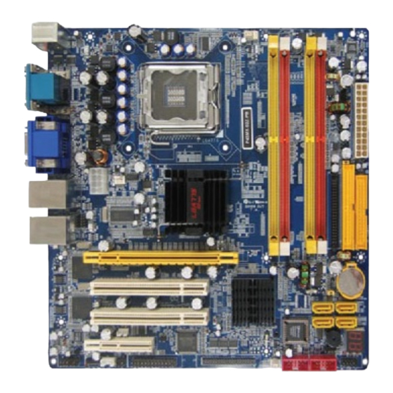
Chapter 1: Pre-Configuration Jumper Locations Use the diagram below and the tables on the following pages to locate and set the on-board configuration jumpers. Figure 1-1 Jumper Locations Downloaded from StockCheck.com... -
Page 12: Cmos Reset
Phoenix MicroATX Express Memory Configuration The Phoenix MicroATX Express offers 4 DIMM memory sockets (Locations DIMM1,2,3 and 4 – Figure 1-2). They can be configured with 1.8V SDRAM DDR2 DIMM modules. It is very important that the quality of the DIMMs is good. -
Page 13: Cpu Installation
3. Always use a heat-sink and a CPU fan. Locate the CPU socket on your Phoenix MicroATX Express system board (Socket LGA775 – Figure 1-2). To install a CPU, first turn off your system and remove its cover. Locate the LGA775 socket and open it by first pulling the level sideways away from the socket then upward to a 90-degree angle. - Page 14 If the Phoenix MicroATX Express industrial embedded motherboard is acquired without the CPU and the thermal solution, extremely care must be taken to avoid improper thermal management. All Intel thermal solution specifications, design guidelines and suggestions to the CPU being used must be followed.
- Page 15 Chapter 1: Pre-Configuration Socket Load Plate Open. Disengage Load Lever by depressing down and out on the hook to clear retention tab Rotate Load Lever to fully open position at approximately 135degrees iii. Rotate Load Plate fully open position approximately 100degrees Socket Load Lever Open 2.
- Page 16 Phoenix MicroATX Express – Installation Guide 775- Land LGA Package Insertion • Lift processor package from shipping media by grasping the Press to remove substrate edges ONLY. Note: Orient processor package such that the Pin 1 triangle mark is on bottom left and both key notches are on left side •...
- Page 17 Chapter 1: Pre-Configuration Intel Reference Thermal Solution Assembly NOTE: Depending on the configuration, Thermal Solution Integration procedure could perform with M/B alone or with M/B in the Chassis. 0.150-inch backside clearance for fastener installation Fan cabled on side Place motherboard on support structure providing closest to MB header minimum 0.150-inch backside clearance Apply 300 mg of Thermal Interface Material onto center...
-
Page 18: Installing Cables
Installing Cables Power and Control Panel Cables The Phoenix MicroATX Express gets power from the ATX connector J32 (Figure 1-2) and ATX 12V J24 (Figure 1-2). Power Connector (24-pin block): ATXPWR24P(J32) ATX Power Supply connector. -
Page 19: Installing Peripheral Cables
Chapter 1: Pre-Configuration If you intend to use a PSU with 20-pin and 4-pin power plugs, make sure that the 20-pin power plug can provide at least 15A on +12V and the power supply unit has a minimum power rating of 350W. The system may become unstable or may not boot up if the power is inadequate. - Page 20 Then connect remaining ends of the ribbon cable to the appropriate peripherals. This concludes the hardware installation of your Phoenix MicroATX Express system. Now it is a good time to re- check all of the cable connections to make sure they are correct.
- Page 21 Chapter 1: Pre-Configuration Figure 1-2 Location of Components and Connectors Downloaded from StockCheck.com...
-
Page 22: Index Of Connectors
Phoenix MicroATX Express – Installation Guide Figure 1-3 Back Panel Index of Connectors Please refer to Appendix A for pin-out descriptions. Table 1-7 Connectors description Connector Description DIMM1 DDR2 SDRAM module socket 1 DIMM2 DDR2 SDRAM module socket 2 DIMM3... - Page 23 Chapter 1: Pre-Configuration Connector Description IrDA – Infra Red Port USB (Ports 0 & 1) - Header USB (Ports 2 & 3) - Header SYS FAN RIWAKE ATX 12V Power Connector Serial ATA2 IDE Connector 1 Serial ATA2 IDE Connector 2 Serial ATA2 IDE Connector 3 Serial ATA2 IDE Connector 4 ATX Power Connector...
-
Page 24: Chapter 2 Amibios8 Setup
Chapter 2 AMIBIOS8 Setup Your Phoenix MicroATX Express features American Megatrends AMIBIOS8. The system configuration parameters are set via the BIOS setup. Since the BIOS Setup resides in the ROM BIOS, it is available each time the computer is turned on. - Page 25 Chapter 2:BIOS Configuration The <F8> key on your keyboard is the Fail-Safe key. It is not displayed on the ezPORT key legend by default. To set the Fail-Safe settings of the BIOS, press the <F8> key on your keyboard. It is located on the upper row of a standard 101 keyboard.
- Page 26 Phoenix MicroATX Express – Installation Guide Downloaded from StockCheck.com...
-
Page 27: Main Setup
Chapter 2:BIOS Configuration Main Setup When you first enter the ezPORT Setup Utility, you will enter the Main setup screen. You can always return to the Main setup screen by selecting the Main tab. There are two Main Setup options. System Time/System Date Use this option to change the system time and date. - Page 28 Phoenix MicroATX Express – Installation Guide IDE CONFIGURATION SCREEN IDE Configuration Settings You can use this screen to select options for the IDE Configuration Settings. Use the up and down <Arrow> keys to select an item. Use the <Plus> and <Minus> keys to change the value of the selected option. A description of the selected item appears on the right side of the screen.
- Page 29 Chapter 2:BIOS Configuration 720 KB 3 ½ ” Set this value if the floppy disk drive attached to the corresponding channel is a 720 KB 3½ “ floppy disk drive. 1.44 MB 3 ½ ” Set this value if the floppy disk drive attached to the corresponding channel is a 1.44 MB 3½ “ floppy disk drive.
- Page 30 Phoenix MicroATX Express – Installation Guide Disabled Set this value to prevent the serial port from accessing any system resources. When this option is set to Disabled, the serial port physically becomes unavailable. 3F8 Set this value to allow the serial port to use 3F8 as its I/O port address. This is the default setting. The majority of serial port 1 or COM1 ports on computer systems use I/O Port 3F8 as the standard setting.
- Page 31 Chapter 2:BIOS Configuration HARDWARE HEALTH CONFIGURATION SCREEN Hardware Health Configuration Screen Shows information about temperatures and voltages. Allows control of several environmental functions. The function can be enabled or disabled. Downloaded from StockCheck.com...
- Page 32 Phoenix MicroATX Express – Installation Guide ACPI CONFIGURATION SCREEN ACPI Configuration Screen You can use this screen to select options for the ACPI settings. Use the up and down <Arrow> keys to select an item. Use the <Plus> and <Minus> keys to change the value of the selected option.
-
Page 33: Pci/Pnp Setup
Chapter 2:BIOS Configuration Set this value to allow the ACPI BIOS to add a pointer to an OEMB table in the Root System Description Table (RSDT) table. Disabled This option disables adding an OEMB table. Enabled This option enables adding an OEMB table. This is the default setting. Note: OEMB table is used to pass POST data to the AML code during ACPI O/S operations. - Page 34 Phoenix MicroATX Express – Installation Guide Yes The Yes setting allows the operating system to change the interrupt, I/O, and DMA settings. Set this option if the system is running Plug and Play aware operating systems. PCI Latency Timer Set this value to allow the PCI Latency Timer to be adjusted. This option sets the latency of all PCI devices on the PCI bus.
-
Page 35: Boot Setup
Chapter 2:BIOS Configuration IRQ14 IRQ15 Available This setting allows the specified IRQ to be used by a PCI/PnP device. This is the default setting. Reserved This setting allows the specified IRQ to be used by a legacy ISA device. Set this value to allow the DMA setting to be modified. The optimal and Fail-Safe default setting is Available. DMA Channel 0 DMA Channel 1 DMA Channel 3... - Page 36 Phoenix MicroATX Express – Installation Guide Quiet Boot Set this value to allow the boot up screen options to be modified between POST messages or OEM logo. The Optimal and Fail-Safe default setting is Enabled. Disabled Set this value to allow the computer system to display the POST messages.
- Page 37 Chapter 2:BIOS Configuration BOOT DEVICE PRIORITY Boot Device Priority Use this screen to specify the order in which the system checks for the device to boot from. To access this screen, select Boot Device Priority on the Boot Setup screen and press <Enter>. Boot Device Boot Device Boot Device...
-
Page 38: Security Setup
Phoenix MicroATX Express – Installation Guide Use this screen to view the hard disk drives in the system. To access this screen, select Hard disk drives on the Boot Setup screen and press <Enter>. REMOVABLE DEVICES Removable Devices Use this screen to view the removable drives attached to the system. To access this screen, select Removable Devices on the Boot Setup screen and press <Enter>. - Page 39 Chapter 2:BIOS Configuration • Boot Sector Virus Protection Supervisor Password Indicates whether a supervisor password has been set. If the password has been installed, Installed displays. If not, Not Installed displays. User Password Indicates whether a user password has been set. If the password has been installed, Installed displays. If not, Not Installed displays.
-
Page 40: Chipset Setup
Phoenix MicroATX Express – Installation Guide appears. Type the password and press <Enter>. The screen does not display the characters entered. Retype the password as prompted and press <Enter>. If the password confirmation is incorrect, an error message appears. The password is stored in NVRAM after ezPORT completes. - Page 41 Chapter 2:BIOS Configuration VIDEO FUNCTION CONFIGURATION For ADD2 cards SOUTH BRIDGE CONFIGURATION Downloaded from StockCheck.com...
-
Page 42: Exit Menu
Phoenix MicroATX Express – Installation Guide Exit Menu Select the Exit tab from the ezPORT setup screen to enter the Exit BIOS Setup screen. You can display an Exit BIOS Setup option by highlighting it using the <Arrow> keys. All Exit BIOS Setup options are described in this section. -
Page 43: Chapter 3 Upgrading
Chapter 3 Upgrading Upgrading the Microprocessor The latest revision of the Phoenix Micro ATX Express currently supports Intel Pentium 4 processors in an LGA775 processor socket with a 1066, 800, or 533 MHz system bus. Use Only ATX12V compliant power supplies. - Page 44 Phoenix MicroATX Express – Installation Guide Dual channel (Interleaved) mode. This mode offers the highest throughput for real world applications. Dual channel mode is enabled when the installed memory capacities of both DIMM channels are equal. Technology and device width can vary from one channel to the other but the installed memory capacity for each channel must be equal.
-
Page 45: Appendix A Technical Specifications
Appendix A: Technical Specifications Appendix A Technical Specifications Chipsets Core Logic North Bridge - Intel 945G. South Bridge – Intel ICH7R. Peripheral I/O Standard Microsystems (SMSC) SCH311x. BIOS System BIOS American Megatrends AMIBIOS8. Flash BIOS Standard feature for System BIOS. Flash programming built into the BIOS. BIOS to be flashed is read from a floppy. -
Page 46: Industrial Devices
The BIOS supports Logical Block Addressing (LBA) and Extended Cylinder Head Sector (ECHS) translation modes. The drive reports the transfer rate and translation mode to the BIOS. The Phoenix MicroATX Express supports Laser Servo (LS-120) diskette technology through the Parallel ATA IDE interface. -
Page 47: Miscellaneous
Appendix A: Technical Specifications Automatic CPU voltage & temperature monitoring device embedded on the peripheral I/O controller. Power Management Power button function: advanced power management support. Post Code Display Miscellaneous CMOS/Battery RTC with lithium battery. Control Panel Connections Reset, Soft Power. LEDs for power and IDE. CPU Socket LGA775 socket. -
Page 48: Memory Map
Phoenix MicroATX Express – Installation Guide Memory Map Address Range Address Range Decimal Size Description Hexadecimal 960K-1M 0F0000-0FFFFF 64 KB Upper BIOS 896K-960K 0E0000-0EFFFF 64 KB Lower BIOS Expansion Card BIOS and 768K-896K 0C0000-0DFFFF 128 KB Buffer Standard PCI/ISA Video... -
Page 49: Interrupts
Appendix A: Technical Specifications Address (hex) Description 00C0-00DE DMA 2 00F0 Coprocessor Error 0170 _ 0177 Secondary IDE channel 01F0 _ 01F7 Primary IDE channel 0278-027F LPT2 (if selected) 02E8-02EF COM4 (default) 02F8-02FF COM2 (default) 0376 Secondary IDE channel command port 0377 Floppy channel 2 command 0377, bit 7... -
Page 50: Smbus
Phoenix MicroATX Express – Installation Guide SMBUS Device Slave Address 00101101b DIMM0 01010000b DIMM1 01010001b DIMM2 01010010b DIMM3 01010011b Clock Chip Write 11010010b Clock Chip Read 11010011b PCI Interrupt Routing Map PCI Device ID SEL PIRQA PIRQB PIRQC PIRQD PIRQE... - Page 51 Appendix A: Technical Specifications Table A-10 Serial Port COM2 DB9 Connector J4B Pin# Serial Port COM 2 – J4B Table A-11 Serial Port COM3-6 Header Connector J2 (Optional) Pin# Serial Port COM3-6 Header – J2 DCD3 DSR3 RTS3 CTS3 DTR3 DCD4 DSR4 RTS4...
- Page 52 Phoenix MicroATX Express – Installation Guide RTS6 CTS6 Table A-12 J41 Ethernet Header Pin# Ethernet Header Connector – J41 2.25V STDBY MDI +0 MDI -0 MDI +1 MDI -1 MDI +2 MDI -2 MDI +3 MDI -3 Table A-13 J16 USB Ports 0 & 1 Header Connector Pin# USB Header –...
- Page 53 Appendix A: Technical Specifications +D – USB2 +D – USB3 GROUND – USB2 GROUND – USB3 Over Current Table A-15 J19 SPI Header Connector Pin# SPI Header – J19 MOSO MOSI Table A-16 J7 Front Panel Header Connector Pin# Front Panel Header – J7 HDD LED Anode Power LED Green Blink HDD LED Cathode...
- Page 54 Phoenix MicroATX Express – Installation Guide Table A18 J1 Parallel Header Connector Pin# Parallel Header – J1 -STROBE AUTOFEED +DATA BIT 0 ERROR +DATA BIT 1 INIT +DATA BIT 2 SLCT IN +DATA BIT 3 +DATA BIT 4 +DATA BIT 5...
- Page 55 Appendix A: Technical Specifications Table A-20 CPU Fan, Sys Fan1, Sys Fan2, Ext Temp, RIWAKE, CD IN and Aux IN. Connector Description CPU FAN 1) GND 2)+12V 3) Sense 4) PWM Sys FAN1 1) GND (PWM) 2)+12V 3) Sense Sys FAN2 1) GND (PWM) 2)+12V 3) Sense...
-
Page 56: Appendix B Flash Bios Programming And Codes
Flash BIOS programming and codes The Phoenix MicroATX Express offers the standard FLASH BIOS. When installed, you will be able to update your BIOS without having to replace the EEPROM. The AMIBIOS8 will read the new BIOS file from a floppy disk during boot and replace the old BIOS. - Page 57 Appendix B: Flash BIOS The Runtime module is uncompressed into memory. CPUID information is stored in memory. Store the Uncompressed pointer for future use in PMM. Copying Main BIOS into memory. Leaves all RAM below 1MB Read-Write including E000 and F000 shadow areas but closing SMRAM.
- Page 58 Phoenix MicroATX Express – Installation Guide Traps INT1Ch vector to "POSTINT1ChHandlerBlock." Early CPU Init Start -- Disable Cache - Init Local APIC Set up boot strap processor Information Set up boot strap processor for POST Enumerate and set up application processors...
- Page 59 Appendix B: Flash BIOS F000h segment with 0FFh. Initializes the Microsoft IRQ Routing Table. Prepares the runtime language module. Disables the system configuration display if needed. Initialize runtime language module. Displays the system configuration screen if enabled. Initialize the CPU’s before boot, which includes the programming of the MTRR’s.
-
Page 60: Critical Error Beep Codes
Phoenix MicroATX Express – Installation Guide 1 = On-board System devices. 2 = ISA devices. 3 = EISA devices. 4 = ISA PnP devices. 5 = PCI devices. Table B-5 ACPI Runtime Checkpoints ACPI checkpoints are displayed when an ACPI capable operating system either enters or leaves a sleep state. The... - Page 61 Appendix B: Flash BIOS User's Notes: Downloaded from StockCheck.com...
-
Page 62: Appendix C On-Board Industrial Devices
Appendix C On-Board Industrial Devices The Phoenix MicroATX Express offers one or two Gigabit Ethernet controller and up to six serial ports (one optional RS422/485). The Phoenix MicroATX Express also offers three other On-Board Industrial devices: Watchdog timer, Hardware health monitor and a Post Code display that will help you on troubleshooting. -
Page 63: Serial Ports
Appendix C: Industrial Devices Serial Ports The Phoenix MicroATX Express can be configured with up to six fixed RS-232 serial ports (COM1 RS-422/485 optional). COM1 and COM2 are standard, the others are optional. TIA/EIA-232 RS is the abbreviation for recommended standard. Usually, it is based on or is identical to other standards, e.g., EIA/TIA-232-F. - Page 64 Phoenix MicroATX Express – Installation Guide Advantages of Single-Ended Transmission The advantages of single-ended transmission are simplicity and low cost of implementation. A single-ended system requires only one line per signal. It is therefore ideal for cabling, and connector costs are more important than the data transfer rate, e.g.
- Page 65 Appendix C: Industrial Devices Differential, Point-to-Point Differential, Multi-Drop Differential Transmission For balanced or differential transmission, a pair of signal lines is necessary for each channel. On one line, a true signal is transmitted, while on the second one, the inverted signal is transmitted. The receiver detects voltage difference between the inputs and switches the output depending on which input line is more positive.
- Page 66 Phoenix MicroATX Express – Installation Guide Electrical TIA/EIA-485 describes a half-duplex, differential transmission on cable lengths of up to 1200 m and at data rates of typically up to 35 Mbps (requirement similar to TIA/EIA-422, but tr<30% of the bit duration, there are also faster devices available, suited for higher rates under certain load-conditions).
- Page 67 Appendix C: Industrial Devices Downloaded from StockCheck.com...
-
Page 68: Appendix On-Board Video Controller
Appendix D: On-Board Video Appendix On-Board Video Controller The Phoenix MicroATX Express has an On-board video controller. The On-board video controller is based on the Intel 945G GMCH. Graphics Features Intel 945G Graphics Subsystem The Intel 945G chipset contains two separate, mutually exclusive graphics options. Either the GMA950 graphics controller (contained within the 82945G GMCH) is used, or a PCI Express x16 add-in card can be used. - Page 69 Appendix D: On-Board Video system memory is installed. DVMT returns system memory back to the operating system when the additional system memory is no longer required by the graphics subsystem. DVMT will always use a minimal fixed portion of system physical memory (as set in the BIOS Setup program) for compatibility with legacy applications.
- Page 70 Phoenix MicroATX Express – Installation Guide User's Notes: Downloaded from StockCheck.com...
- Page 71 Downloaded from StockCheck.com...
- Page 72 MN-P45MX-01 Downloaded from StockCheck.com...
Need help?
Do you have a question about the MicroATX Express and is the answer not in the manual?
Questions and answers