Advertisement
Quick Links
Advertisement

Summary of Contents for Kobastar WEI
- Page 1 WEI WIRELESS INDICATOR USER MANUAL...
- Page 2 CONTENTS 1. General Description 2.Technical Specifications 3. Description of Function Keys 4.Use of the Device 5.Menular Login 6.Menu Tree...
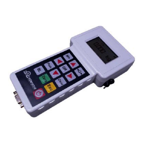
- Page 3 WEI Wireless indicator is a wireless industrial weighing indicator that can communicate up to 100 meters in an open area designed especially for axle scales, cranes and dynamometers. WEI, which can be connected to 16 different load cells, can display all incoming weight information individually and in total on the graphic display.
- Page 4 3. EXPLANATION OF FUNCTION KEYS It collects and saves the weight value shown on the screen each time it is pressed. This saved value can be deleted with the Clear key. Performs zero calibration in weighing condition. Each time it is pressed, it sends the weight information to the printer. It is used to enter the menus and to switch the menus.
- Page 5 4. USE OF THE DEVICE 4.1 MAIN SCREENING FORM 1) This icon indicates the wireless signal strength. If there is more than one transmitter, it shows the signal strength of the farthest transmitter. If no transmitter sends a signal, a no signal sign will appear.
- Page 6 4.2 SINGLE SCREENING FORM Press the key to switch from the main display to the single display. In single display, the transmitter number and the load value are displayed opposite it. If the transmitters do not work or there is no signal, the line is shown. 4.3 RESET SCREEN Press the key to enter the reset menu.
- Page 7 In the single reset menu, the desired scale is selected with the up arrow or down arrow and the weighing weight data of the selected scale is displayed on the screen.In this menu if you pres the key, resetting is done in the selected scale. Press * ESC + key to exit the menu and return to the main display.
- Page 8 4.6 RS232 Output Connection and Printer Format D-Sub 9 pin female RS232 serial port connector is used on WEI. Connection method is as follows. In the Parameter menu, the printing format to be taken from the printer is selected according to the product used.
- Page 9 5. ENTER THE MENU In order to enter the menus, the key is pressed while in the weighing menu and the password menu is entered. Password value is selected as 0001 or 0002 or 0003. You can browse through the menus with the * OK + key.
- Page 10 5.1.2 Closing Time Hand terminal closing time is determined. At the end of the set time, the device turns off. If the "No Power Off" option is selected, the device does not turn off automatically, in this case it must be turned off with the power button.
- Page 11 5.1.6 Division It is the amount of change of weight values displayed on the screen. Graduation values can be selected as 1, 2, 5, 10, 20, 50, 100. 5.1.7 Unit It is the unit of weight seen on the screen. It can be changed to kg, t, lb, kN. 5.1.8 Number of Transmitters The number of transmitters used is entered.
- Page 12 If it is 2%, resetting can be done at values up to 2% of capacity by weight. 5.1.10 Print Option The printing format to be taken from the printer is selected according to the product used. 1- Dynamometer 2- Axle Scale 5.1.11 Channel Setting Channel assignment is made for the transmitter used in the load cell.
- Page 13 5.1.13 Time Clock setting can be made with the up / down / right / left buttons. 5.1.14 Date Date setting can be made with the up / down / right / left buttons.
- Page 14 5.2 CALIBRATION 5.2.1 Calibration Option Load calibration is performed by placing a reference weight in the loaded calibration. In mV calibration, load cell capacity and millivolt values are entered and no-load calibration is performed. 5.2.2 Selecting Hardware Hardware / Rope - select menu for crane hoist system. It can be selected from 0 to 5.
- Page 15 5.2.3 Decimal Point The integer and fractional part of the decimal number are selected. DECIMAL POINT 000000 00000.0 0000.00 000.000 5.2.4 LoadCell Capacity The maximum capacity value of LoadCell is entered. Example: 10000 kg 5.2.5 Calibration processes For load calibration or mV calibration, the relevant transmitter is left on and the others are turned off.
- Page 16 In the displayed menu, the open transmitter number is displayed and the zero load internal count value is saved. In load calibration, a calibration load of at least 1/3 of the capacity is placed on the platform and the * OK + key is pressed. In the menu displayed in load calibration, the loaded internal count value is taken, then the calibration load value is entered and the * OK + key is pressed.
- Page 17 6. Menu Tree 6. 1 Parameter Menu...
- Page 20 6.2 Calibration Menu 6.2.1 Load Calibration...
- Page 22 6.2.2 mV Calibration...
- Page 24 6.3 Crane Hoist System Menu...
Need help?
Do you have a question about the WEI and is the answer not in the manual?
Questions and answers