
Related Manuals for Serveredge SED-KLHDMI-0819

Summary of Contents for Serveredge SED-KLHDMI-0819
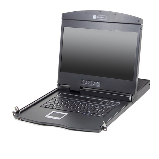
- Page 1 USER’S MANUAL Serveredge 8 and 16 port HDMI LCD KVM switch series USER MANUAL PART NUMBER: SED-KLHDMI-0819, SEDKLHDMI-1619 W: www.serveredge.com P: 1300 335 797 E: info@serveredge.com.au...
- Page 2 STATEMENT UNITED STATES FEDERAL COMMUNICATIONS COMMISSION INTERFERENCE STATEMENT This product has been tested and found to comply with FCC regulations Class B (Class B) digital device and FCC specifications Details of Section 15. T hese specifications are intended to be used in a commercial environment without harmful interference and to provide for the protection of regulated equipment.
- Page 3 USER PRECAUTIONS The manufacturer has the right to modify and alter the information, documentation and specifications contained in this manual without prior notice. Manufactures makes no warranty, express, implied or statutory, disclaims or specifically disclaims it’s possibility of sale and applicability for a particular purpose. The same applies to any sold and authorized manufacturer’s software described in this manual.
-
Page 4: Table Of Contents
CONTENTS About this manual .................... 5 Common Terms ....................5 Chapter IV Chapter I Introduction ......................6 OSD Operation ....................18 • Product description ..................6 • Introduction to OSD ..................18 • Product Features ................... 6 • OSD login ......................18 •... -
Page 5: About This Manual
ABOUT THIS MANUAL This User Manual will assist you in the effective use of product features, including the installation, setup, and operation of your equipment. You can find out what is included in this manual from the following: Chapter I Introduction – This chapter introduces the rack-based KVM device system, including its functions, features, and benefits, and describes and describes its front and rear panel components. -
Page 6: Chapter I
CHAPTER I INTRODUCTION PRODUCT DESCRIPTION The 8/16-port USB Rack KVM Switch is a versatile device that allows administrators to access an 8/16 HDMI computer from a set of USB keyboards, mice,or a set of PS2 keyboards, mice, and consoles. Provides four easy ways embodiment, the installation can be switched computer architecture: (1) connecting the port select buttons using a switch on the front panel;... -
Page 7: Hardware Requirements
HARDWARE REQUIREMENTS CONSOLE • A set of HDMI display screens that are compatible with the highest resolution of any computer to be installed under the installation architecture • A set of USB interface mouse • A set of USB interface keyboard COMPUTER The following devices must be installed on each computer: •... -
Page 8: Component
COMPONENT FRONT VIEW Numbering component Functional description According to the serial number of the switching port, the user can press the corresponding serial number button to switch the corresponding port to the current operating port, and at the Port switch selection button same time, the internal buzzer of the device will be heard, and the switching action is confirmed to be performed correctly. -
Page 9: Rear View
REAR VIEW 16-port KVM rear view 8-port KVM rear view 4-port KVM rear view Numbering component Functional description Connect one end of the HDM connector of the corresponding KVM cable to the HDMI port of the computer and monitor, connect the TYPE B of KVM connection port the USB to the corresponding port of the KVM, and connect the TAPE A port of the other end to the USB port of the computer. -
Page 10: Hardware Installation
CHAPTER II HARDWARE INSTALLATION STACKING AND INSTALLATION Regarding the placement of LCD KVM important safety information switch has been listed in the Appendix in, please first check the contents before operating. Before installation, please make sure that all the devices you are connected to are powered off. You must unplug all the computer power cords with keyboard power on function. -
Page 11: Standard Rack Mounting (Dual Rail Series)
STANDARD RACK MOUNTING (DUAL RAIL SERIES) Screw the front flange to the rack first. Slide the bars with Slide the LCD KVM device into the support flange, use the rear flange towards the rack until the flanges make screw in this package provided with wire front portion of contact with the rack, then screw the rear flanges to the this switch is fixed to the front of the rack and locked. -
Page 12: Assembly And Disassembly Of Kvm Modules
ASSEMBLY AND DISASSEMBLY OF KVM MODULES The LCD panel and keyboard and mouse components of this series can be removed and separated from the KVM part of the rear. This design allows you to change the KVM components as needed, or remove the KVM components after the KVM components are damaged and return them to the manufacturer for repair and replace. - Page 13 • Loading and unloading of dual slide rail modules: Now put this series of products on the appropriate Remove the KVM assembly and the front LCD assembly operating platform, and prepare the screwdriver tool for by removing the KVM assembly and the mounting subsequent disassembly screws.
-
Page 14: Keyboard Module Removal
KEYBOARD MODULE REMOVAL If you need to replace the keyboard of the LCD module part or repair this part, you can also disassemble according to the following figure. Place the LCD KVM on the rack and fix it, and flip the LCD There is a circular hole at the bottom of the keyboard panel to expose the operating surface of the keyboard and panel. -
Page 15: Single Device Installation
SINGLE DEVICE INSTALLATION Note: Please confirm the power failure status of the equipment before installation. To prevent equipment damage during installation, please confirm that all installed equipment has good grounding protection. Plug your USB keyboard and mouse into the USB console port on the switch’s back panel. The HDMI display video signal line is connected to the HDMI control terminal port and powered. -
Page 16: Basic Operation
CHAPTER III BASIC OPERATION HOT PLUG The KVM switch supports hot-plug, removing and removing components by unplugging the cables connected to the computer’s port without shutting down the switch. To make the hot swap function work properly, follow these steps: Hot –... -
Page 17: Hotkey Selection
Hotkey selection This product offers four hotkey switching methods [SCRLL] + [SCRLL] + [NUM] [CTRL]+[CTRL]+[NUM] [ALT]+[ALT]+[NUM] [SHIFT] + [SHIFT] + [NUM] The default hotkey switching combination key is [SCRLL]+[SCRLL]+[NUM] where [NUM] is the keyboard number 1-16, and the keyboard combination hotkey is input to complete the carriage return completion command, and the KVM switch will switch the corresponding number. -
Page 18: Osd Operation
CHAPTER IV OSD OPERATION OSD INTRODUCTION OSD (On Screen Display), provides a menu driven interface to handle the computer switching procedure to provide instant access to any computer on the installation. OSD LOG IN The OSD function provides a two-level (administrator / user) password mechanism. The factory default setting is no need to login password authentication, so you are the first time to open the OSD main menu, no need to enter the login password to enter the OSD main menu screen for the corresponding operation. -
Page 19: Osd Function Key Introduction
OSD INTRODUCTION Heading Explanation This column lists the port numbers for all the CPU ports on the installation. The simplest method to access a particular computer is to move the highlight bar to it, then press [Enter]. If a port has been selected for Quick View scanning, an arrowhead symbol displays in this column to indicate so. -
Page 20: F2 Scan
F2 SCAN Press the [F2] key to start the SCAN function. The SCAN function allows the KVM device to automatically switch the connection port. You can set and view it according to the set time interval. To end the SCAN scan, press the [Space] button to exit the scan mode. -
Page 21: F5 Edit
F5 EDIT Press the [F5] key to set or edit the name of the current port. The maximum number of characters that can be input is 15, and the setting is completed when [ENTER] is confirmed. The user can set the name by combining letters and numbers as needed. - Page 22 OSD ACTIVATING HOTKEY This function sets and changes the startup shortcut hotkey combination of the OSD menu. This device provides 4 hotkey menu combinations: [CTRL]+[CTRL], [SCROLL]+[SCROLL], [ALT]+[ALT], [SHIFT]+[SHIFT] You can use the keyboard as needed [↑] [↓] The arrow keys move the cursor to select, and then press the [Enter] key to save.Initially, [CTRL] [CTRL] is used as the startup hotkey for the OSD menu.
- Page 23 SCAN DURATION Change function can set the interval of port switching in SCAN mode. You can use the keyboard [↑] [↓] arrow keys to move the cursor to select, and then press [Enter] to save. The initial default setting is 5 seconds. SET PASSWORD This function can set the function permission of the general user.
- Page 24 CLEAR THE NAME LIST This function can clear the NAME setting of all ports. This function needs to verify the administrator ID and password to implement. The password will pop up prompt: CLEAR ALL THE NAME ? [N], if you want this operation to take effect, please enter [Y], then enter the keyboard [Enter] to confirm the effect;...
-
Page 25: Appendix
APPENDIX SAFETY INSTRUCTION IN GENERAL • This product is for indoor use only. • Please read all the instructions for future reference. • Follow all the warnings and instructions on the device. • Do not place this equipment on any unstable surface (such as cart, stand, table, etc.). If this equipment falls, it will cause serious damage. - Page 26 • If any of the following conditions occur, unplug the unit from the wall outlet and return it to a qualified service representative for repair. - The power cord or plug is damaged or worn - Liquid is spilled into the unit - The device is exposed to rain and water - The device has been dropped or the housing has been damaged - The function of the device is obviously changed...
-
Page 27: Product Specification
SPECIFICATIONS 16 ports Features Single port 4 ports 8 ports Computer connections Port selection OSD menu, panel buttons, hotkeys monitor 1 x HDMI female Control port keyboard 1 x USB Type A female mouse 1 x USB Type A female Connector monitor, 1 x HDMI female... -
Page 28: Warranty Conditions
WARRANTY CONDITIONS The Company shall not be liable for damages up to the amount paid by the Customer for the Products. In addition, the Company does not assume any direct, indirect, special, incidental or consequential damages resulting from the use of this product or the enclosed CD-ROM, documentation, etc…;... - Page 29 W: www.serveredge.com P: 1300 335 797 E: info@serveredge.com.au...
Need help?
Do you have a question about the SED-KLHDMI-0819 and is the answer not in the manual?
Questions and answers