
Related Manuals for Telenot B&B F10

Summary of Contents for Telenot B&B F10
- Page 1 RADIO CONTROL FOR FORESTRY CABLE WINCHES F10 ET F10 DT OPERATING INSTRUCTIONS January 2014 english...
- Page 2 TELENOT ELECTRONIC GMBH B & B Product Division Wiesentalstraße 42 D 73434 Aalen GERMANY Tel. +49 7361 946-4813 Fax +49 7361 946-440 E-Mail: service@forest-frequency.com Internet: http://www.forest-frequency.com Translation of the German original operating instructions...
-
Page 3: User Notes
User notes User notes Use of the operating instructions First read the operating instructions through in their entirety These operating instructions enable the safe and efficient use of before putting the remote control into operation, and store the the radio control for F10 forestry cable winches. operating instructions away in a suitable protective cover at the All stated safety notices and instructions must be observed to location of use so they can be accessed readily. - Page 4 User notes Limitation of liability General Sales Terms All technical information in this description has been created The General Conditions of Sale are included on the website at with the utmost care. Nevertheless, errors cannot be totally http://www.funk-im-forst.de. excluded. Therefore, we would like to draw your attention to the Return faulty devices fact that we cannot assume any legal responsibility or any type To avoid damage during transport, choose stable and robust...
- Page 5 Product identification Manufacturer For queries, complaints, or parametrization requests, you must TELENOT ELECTRONIC GMBH specify the device serial number. The receiver ID is located on B & B Product Division the housing panel. The transmitter ID is located on the rear side Wiesentalstraße 42...
- Page 6 User notes Requirements for secure operation Explanation of symbols Symbols indicate safety guidelines and warning notices. The symbol is accompanied by a signal word that conveys the extent NOISE! of the danger. Hearing damage due to noise! It is essential to observe these notices to avoid accidents, perso- nal injury, and damage to property! Tips and recommendations for correct operation DANGER!
-
Page 7: Table Of Contents
Table of content Table of content 7.2.3 Receiver features..... . 19 7.2.4 Options ......20 User notes . - Page 8 Table of content 11.2 F10 E receiver ......37 17.3 F10 S transmitter ..... . 53 11.2.1 Assembly location requirements .
-
Page 9: Safety Notes
Safety notes Safety notes People carrying medical devices should check the compati- bility of their devices with the radio control unit that is built The operating instructions provide important information for according to EN 62479. handling the device. All stated safety notices and instructions must be observed to ensure safe working. - Page 10 Safety notes DANGER! Requirements for safe operation Danger from unintentional triggering of functions or starting up Wear protective work clothing suitable for the activity and Ensure that no unintended actuation of the transmitter the deployment location (PPA). can be caused by items of clothing and such like. Before switching on the radio control, ensure that nobody Switch the transmitter off...
-
Page 11: Special Risks
Safety notes Special risks 3.3.3 Short circuit WARNING! 3.3.1 Defective control elements Fire hazard from short circuits! CAUTION! In the event of a short circuit, very high currents may Residual risk! occur which could heat up plug connections and cables The receiver itself does not trigger any dangerous com- considerably, for example. -
Page 12: Handling Packaging Materials
Safety notes 3.4.2 Handling packaging materials Storage and handling the transmitter battery (eneloop®) Packaging materials are valuable raw materials which can often be used further or reprocessed appropriately and recycled. Batteries gradually lose capacity with age and operating times become shorter. Only recharge the battery when it is empty. -
Page 13: Conduct In The Event Of Danger And Accidents
Inform the manager at the location of use. must not be disposed of with domestic waste! Notify a doctor and/ or the fire department. Batteries purchased from TELENOT can be returned free NiMH Clear access routes for rescue vehicles. of charge, where they are disposed of properly. -
Page 14: Delivery
Delivery Delivery Art.-No. Name Delivery 109536000 F10 ET radio control - F10 S ET transmitter - F10 E receiver with connection cable and plug - Pin assignment diagram, valid for your winch - 230 V battery charger A-LG 230 V - Accessories kit with 4 NiMH Sanyo eneloop® AA batteries in a plastic box, waist belt and chest carrying belt, 3 metal vibration dampers for F10 E receiver and B&B pen - F10 original operating instructions - F10 original operating instructions English translation... -
Page 15: System Overview
System overview System overview Transmitter Transmitter F10 S (ET) F10 S (DT) The F10 radio control is used for the wireless control of cable winches. Depending on the model, single (ET) and double-drum winches (DT) of all makes can be controlled. The F10 radio control can be extended with various Winch Winch left... -
Page 16: Function Overview
Function overview Function overview Transmitter The F10 radio control was specially designed for the harsh requi- rements of the forest. Sophisticated radio electronics in a robust housing makes the F10 the optimum device for professional log-moving work. The radio control is suitable both for use on forestry vehicles with permanently attached cable winches and for 3-point cable winches on agricultural tractors and towing vehicles. -
Page 17: Receiver
Function overview The receiver features a diagnostics LED through which impor- Receiver tant output functions and system notifications are displayed using colors (red, green, yellow) and various blinking rhythms. Diagnostics LED This allows quick monitoring of the radio control on site. The receiver is switched on and off... -
Page 18: Device Features
Device features Device features 7.1.2 F10 DT radio control Device variants 7.1.1 F10 ET radio control F10 DT Set F10 DT (ready for connection) for double-drum winches with three additional commands (MAS option) F10 ET Functions Set F10 ET (ready for connection) for single-drum winches with Pull (left/right) two additional commands (optional) Brief and permanent brake release (left/right) -
Page 19: Device Features
Device features Device features 7.2.3 Receiver features Shock-proof housing made from PC/ABS polyamide 7.2.1 General features On/off switch Operationally safe function on the 70-cm ISM band Diagnostics LED Bidirectional radio technology Protection type IP65 3 working channels Dimensions (W x H x D) 152 x 218 x 51/66 mm Individual adjustments to the special circumstances and ty- Operating voltage +10 V to +30 V DC pes of operation of a wide range of winch operating modes. -
Page 20: Options
Device features 7.2.4 Options For F10 ET and F10 DT there are different options which you can order with the package and which are pre-installed at the factory: F10 ET device version Option Art.-No. Note Stutter brake 109536054 Function at the factory (Option SB) Periods are parameterizable Remote aerial... - Page 21 Device features F10 DT device version Option Art.-No. Note Remote aerial 109536050 BNC socket for external aerial installed at the factory (Option AA F10) The external aerial for attaching (art. no. 109535858) or for remote installation (art. no. 109535861) must be ordered separately. Emergency call SPT 109536052 Equipped at the factory with the emergency call SPT comtac 2204-C, housing: W×H×D...
-
Page 22: Functional Description
Functional description Functional description 8.1.2 F10 ET with stutter brake option Structure 8.1.1 F10 ET F10 ET SB transmitter operation options Switch 1 - Operating level 1 (green): Pull drum / release brake - Operating level 2 (gray): Additional command A (e.g. F10 ET transmitter operation options PTO shaft on) / permanent release Switch 1 - Operating level 1 (green): Pull drum / release brake... -
Page 23: F10 Dt
Functional description 8.1.3 F10 DT 8.1.4 F10 receiver F10 DT transmitter operation options Switch 1 - Operating level 1 (green): Pull drum left / release brake left - Operating level 2 (gray): Additional command A (e.g. PTO shaft on) / permanent release left Switch 2 - Operating level 1 (green): Gas + / Gas –... -
Page 24: Functions
Functional description All outputs except "Emergency" are monitored for Diagnostics LED blinking sequence red, yellow: - Siren monitoring has tripped functionality or short circuits and displayed by the dia- gnostics LED in the event of failure. The "Siren" output --> Check the Si5 fuse and the siren supply cable is not monitored with the factory setting;... -
Page 25: Release Brake
Functional description 8.2.2 Release brake Depending on winch type the following operation modes and the time for permanent release are parametrized at the factory: The function "Release brake" (release winch brake) is started by holding the switch in the direction of this Winch type Operation mode icon and is stopped by releasing the switch (inching... -
Page 26: Gas Adjustment
Functional description The function release brake without permanent release Application: can be parametrized at the factory. The motor speed is controlled, for example, on the throttle rods This function is intended for winches with cable ejec- upwards (gas +) or downwards (gas –) by a lifting spindle motor tion in order to prevent accidental permanent release (e.g. -
Page 27: Active Emergency Call Function ("Active Emergency")
Functional description 8.2.4 Active emergency call function ("Active emer- Active emergency triggered by pressing the stop and gency") emergency call switch The active emergency call function is used to summon help First the pre-alarm (2 secs sound, 2 secs pause) and if the person involved in an accident is still capable of trigge- after 60 secs the main alarm (1 sec sound, 1 sec pause) ring an active emergency call. -
Page 28: Passive Emergency Call Function ("Passive Emergency")
Functional description 8.2.5 Passive emergency call function ("Passive emer- Passive emergency gency") criterion Siren The passive emergency call function is used to summon help if the person involved in an accident is no longer capable of 300 s 180 s Main alarm triggering an active emergency call. -
Page 29: Motor Start / "Motor Stop" (Optional)
Functional description Within the passive emergency period (300 secs) and The option "Motor start" / "Motor STOP" in the F10 ET during the pre-alarm, the next sequence can be stopped model contains the additional command A (e.g. for PTO by withdrawing the passive emergency criterion or by shaft on) and the additional command A and B (for free actuation. -
Page 30: Stutter Brake (Optional)
Functional description 8.2.7 Stutter brake (optional) Requirement: Brief response times of the winch brake The "Stutter brake" option can only be ordered for F10 ET single-drum radio controls. An additional switch Use the function "Stutter brake" only in exceptional is installed for this at the factory. circumstances, because it means increased stress both for the winch mechanics and for the output relay of the receiver. -
Page 31: Remote Aerial Aa F10 (Optional)
Functional description 8.2.9 Remote aerial AA F10 (optional) Attach the aerial to a protected space on the vehicle's rear side to prevent damage. When doing so, no metallic The "Remote aerial" option must be pre-equipped at the parts (with the exception of installation surfaces) factory. -
Page 32: Changing The Radio Channel
Functional description 8.2.11 Changing the radio channel If there are faults due to radio controls being operated in parallel, the radio channel can be changed (factory setting: channel 2). The F10 radio control works on the 70-cm ISM band and can be operated on 3 radio channels: Channel 1: 434.175 MHz Channel 2: 434.475 MHz... -
Page 33: Accessories
Accessories Accessories Name Art.-No. Description External aerial for attachment 109535858 The aerial is stuck directly onto the BNC socket on the receiver. Requirement: Opti- onal remote aerial AA F10 External aerial remote 109535861 The aerial is remotely attached to the vehicle with the enclosed cable. Require- installation ment: Optional remote aerial AA F10. -
Page 34: Mechanical Structure
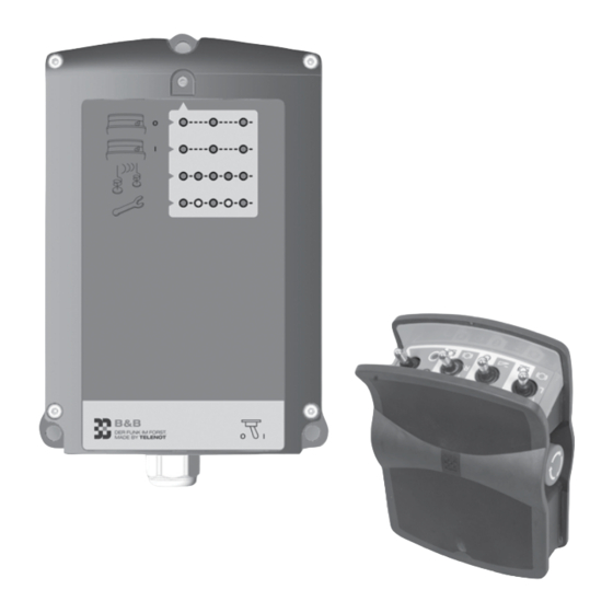
Mechanical structure 10 Mechanical structure 10.2 F10 E receiver 10.1 F10 S transmitter F10 transmitter mechanical design F10 receiver mechanical design Belt plate Mounting clips Stop and emergency switch Cable screw thread Switches for commands Diagnostics LED Battery compartment screw cap On/off switch The receiver of the F10 remote control consists of a two- The transmitter of the F10 remote control consists of a plastic part plastic housing (PC / ABS) with protection class IP65. -
Page 35: Assembly
Assembly 11 Assembly Chest carrying method The transmitter of the F10 radio control can be worn on the 11.1 F10 S transmitter chest using the waist belt and chest belt contained in the package. 11.1.1 Carrying on the body To do this the waist belt must be attached to the transmitter and the chest belt to the waist belt: Hip carrying method The transmitter of the F10 radio control can be worn on the hip... -
Page 36: Mounting With Bracket For Transmitter
Assembly 11.1.2 Mounting with bracket for transmitter Mark the fixing holes using the dimensional sketch. The transmitter of the F10 radio control can be attached to the wall or to the vehicle using the bracket for the HG1 transmitter. Drill appropriate holes for the screws used. Dimensions (W x H x D) 109.5 x 11.5 x 48 mm Depending on the subsoil, use sheet metal screws / Material: Steel plate... -
Page 37: F10 E Receiver
Assembly 11.2 F10 E receiver 11.2.1 Assembly location requirements The receiver must bolted down to the vehicle tightly! To achieve the broadest range possible, the ideal installati- on location is at the rear of the vehicle. Avoid installing in enclosed metal housings to ensure the unhindered emission of the aerial. -
Page 38: F10 E Receiver Installation
Assembly 11.2.2 F10 E receiver installation Mark the fixing holes using the dimensional sketch. Install the receiver vertically with the gable gland down- wards. The aerial must be removed from metal surfaces Drill appropriate holes for the screws used. as far as possible in order to achieve optimum wireless range. -
Page 39: Connections And Interfaces
Connections and interfaces 12 Connections and interfaces 12.2 Connection type The terminals sockets 1–2 and socket 4 are designed as spring- 12.1 Position force terminal strips. Socket 3 is designed as a USB-B socket and Socket 1 (BU1): 8-pole terminal the plug 2 as a 16-pole plug frame for connecting a ribbon cable. -
Page 40: Connection Configuration
Connections and interfaces 12.3 Connection configuration The connections of sockets 1 and 2 are already prewired at the factory to one or several vehicle connectors. The assignment is based on the winch type and is attached to the remote control. 12.3.1 Socket 1 Do not apply any voltage to the outputs! Socket 1 connection configuration... -
Page 41: Socket 2
Connections and interfaces 12.3.2 Socket 2 Socket 2 connection configuration Type Labeling / icon Function Technical Data output Release brake (for F10 DT left) Switches +UB / max. 5 A output Motor start output Gas + Pull drum (for F10 DT left) output Gas –... -
Page 42: Socket 4
Connections and interfaces 12.3.4 Plug 2 12.3.3 Socket 4 Type Function Technical Data Supply +UB for emergency +UB/max. 300 mA Socket 4 connection configuration call SPT Type Labeling / Function Technical Data Supply GND for emergency icon call SPT Free CANH Free CANL output... -
Page 43: Installation
Installation 13 Installation DANGER! Danger from malfunctions due to incorrect cabling The F10 remote control connection cable is already prewired at The receiver may only be connected by a specialist ac- the factory to one or several plugs (e.g. 7-pole vehicle connec- cording to the pin assignment diagram enclosed. -
Page 44: Wiring Diagrams
Wiring diagrams 14 Wiring diagrams Receiver Connection cable Winch / vehicle Earth connection on vehicle chassis, used separately and not simultaneously by other consumers Ground / 0 V Battery Electronics Pre-alarm (alarm device) Siren (pre-alarm) Cut-off switch Loud horn STOP Lift magnet switching to Motor for gas... -
Page 45: Parameterization
Parameterization 15 Parameterization Application: Controlled lowering of loads 15.1 Who performs the parameterization? Description: Nearly all functions are already parametrized at the factory. The winch brake is opened and closed automatically at short, Additional options are also parametrized at the factory. parameterizable time intervals. -
Page 46: Brake Open Time (Ot) Parameterization
Parameterization 15.2.1 Brake open time (OT) parameterization To reduce the open time, press the switch "Stutter brake" towards the body and hold the switch there. Also First set the open time of the brake (OT). It determines the briefly touch the switch for "gas +". Every time "Gas +" is amount of load lowering when the brake is opened. -
Page 47: Brake Closed Time (Ct) Parameterization
Parameterization 15.2.2 Brake closed time (CT) parameterization To reduce the closed time, press the switch "Stutter bra- ke" away from the body and hold the switch there. Also After the open time, set the closed time of the brake (CT). It de- briefly touch the switch for "gas +". -
Page 48: Commissioning
Commissioning 16 Commissioning 16.2.2 Transmitter battery installation 16.1 Requirements Groove for guide tab The correct cabling of the receiver to the winch or to the vehicle has been performed by a specialist according to the relevant pin assignment diagram. The transmitter battery is charged. Groove for guide tab 16.2 Preparation 16.2.1 Receiver connection... -
Page 49: Functional Testing
Commissioning 16.3 Functional testing CAUTION! Hearing damage due to noise! NOTICE! Wear hearing protection when you are working in the Generally perform the following points prior to com- direct vicinity of audible alarm messages (> 85 dBA). mencing work! Remain in the vicinity of audible warning devices only for as long as required. -
Page 50: Fault-Free Operation
Commissioning When using the function "Passive emergency call", Check whether the diagnostics LED on the receiver begins to flicker or becomes darkened in an operating check whether this is performed: Place the transmitter on the ground and wait until the pre-alarm is signaled. state. -
Page 51: Operation
Operation 17 Operation DANGER! Danger from unintentional triggering of functions or 17.1 Safety notices for operation starting up Ensure that no unintended actuation of the transmitter DANGER! can be caused by items of clothing and such like. Danger from vehicles tipping over Switch the transmitter off... -
Page 52: F10 E Receiver
Operation Check whether the waist or chest belt is damaged each Requirements for safe operation time before starting work to prevent the loss of the trans- mitter. Wear protective work clothing suitable for the activity and the deployment location (PPA). 17.2 F10 E receiver Before switching on the radio control, ensure that nobody could be put at risk from operation. -
Page 53: F10 S Transmitter
Operation 17.3.1 F10 S transmitter LED displays 17.3 F10 S transmitter Switch the transmitter on with the on/off switch (tilt to On/off switch the right). Status LED The diagnostics LED on the receiver blinks green. Operating level LED The status LED on the transmitter flashes green (when battery charged). -
Page 54: Release Brake
Operation IMPORTANT OPERATING PROCEDURES ARE EXPLAINED IN Operating level LED THE SECTIONS THAT FOLLOW. Off Operating level 1 17.3.2 Release brake Lights Operating level 2; short when passive emergency up green Lights Operating level 3 (optional); short when passive up red emergency off... -
Page 55: Permanent Release
Operation 17.3.3 Permanent release Operating level 2 (gray background) Operating level 1 (green background) Via function "Release brake" Status LED Operating level LED Status LED Permanent release command through operating level 2 (s-switch principle) Operating level LED Press the on/off button towards "on" and keep it there. Release brake command Operating level LED lights up green. -
Page 56: Pull Drum
Operation 17.3.4 Pull drum DANGER! Danger from vehicles tipping over Ensure that the vehicle has the necessary stability. Check the subsoil. Recommendation: the anti-tipping system option. Status LED Operating level LED DANGER! Pull drum command Danger from pulling up tree trunks Do not touch the towing cable during operation! Press the switch briefly. -
Page 57: Gas
Operation 17.3.5 Gas + 17.3.6 Gas – Status LED Status LED Operating level LED Operating level LED Gas + command Gas – command Press the switch briefly. An increase in motor speed Press the switch briefly. A reduction in motor speed occurs for the duration of actuation. When released the occurs for the duration of actuation. -
Page 58: Motor Start
Operation 17.3.7 "Motor start" Press the switch briefly towards the body ("Motor STOP"). The motor stops if it is running. Within 6 secs following "Motor STOP", press the switch briefly away from the body; the motor is started. This means a motor that is already running is prevented from being started again. -
Page 59: Motor Stop
Operation 17.3.8 Motor STOP 17.3.9 "Additional command A" The "Additional command A" option is parametrized with the option "Motor start/STOP" at the factory. Status LED Status LED Operating level LED Operating level LED Motor STOP command Additional command A command Press the on/off... -
Page 60: Stutter Brake
Operation 17.3.10 "Stutter brake" The "Stutter brake" switch has the same function in both actuation directions. Details: See function description / functions / stutter brake STOP (optional) WARNING! Parameterization of the function stutter brake: see parameteri- Danger from falling load zation / parameterization stutter brake Ensure that nobody is near the load to be lowered. -
Page 61: Active Emergency
Operation 17.3.11 Active emergency When the "Siren" output is activated, the audible pre-alarm phase simultaneously begins (2 secs sound, 2 secs pause, etc.). After a period of time parameterizable at the factory (facto- ry setting: 60 secs) the "Emergency" output is activated and the main alarm is tripped (siren: 1 sec sound, 1 sec pause, etc.). -
Page 62: Reset "Active Emergency
Operation 17.3.12 Reset "Active emergency" Switch the transmitter off by pressing the on/off switch towards "off" (O). Switch the transmitter back on by pressing the on/off switch towards "on" (I). The siren and the "Emergency" (only with main alarm) output are switched off and the alarm is reset. 17.3.13 Switch on "Passive emergency"... -
Page 63: Reset "Passive Emergency
Operation 17.3.14 Reset "Passive emergency" The transmitter must be switched off. During the pre-alarm (siren: 2 secs sound, 2 secs pause) Press the switch ("Pull drum") away from the body and hold the switch there. Cancel the trigger criterion of the passive emergency call: Press the switch ("Gas +") away from the body and hold the switch there. -
Page 64: Switch Off "Passive Emergency
Operation Switch the transmitter "off" by pressing the on/off The transmitter must be switched off. switch towards off (O). Press the switch ("Release brake") towards the body and hold the switch there. Switch the transmitter back on by pressing the on/off switch towards "on"... -
Page 65: F10 Dt Radio Control Device Version
Operation 17.3.16 F10 DT radio control device version With the F10 DT (double drum) remote control device version, the same standard commands for a second winch ("Pull drum", "Release brake") can be performed with the third switch as with the F10 ET remote control device version with the first switch. Here, switch 1 is intended for the left winch and switch 3 for the right winch. -
Page 66: Eliminate Fault States
Operation 17.4 Eliminate fault states Fault Solution Diagnostics LED on the receiver dark Switch on receiver / check voltage supply Diagnostics LED on the receiver flashes red Switch on transmitter / bring transmitter within the receiver's range Diagnostics LED on the receiver flashes alternately, red / Check fuse 5 and supply cable for the siren orange (siren monitoring has tripped) Diagnostics LED on the receiver flashes alternately, two... -
Page 67: Maintenance And Service
Maintenance and service 18 Maintenance and service If you discover a fault: DANGER! 18.1 Recommended maintenance interval Danger from malfunctions Carry out maintenance work at least once annually. Work can no longer be performed with a defective system. Send back the whole system for repair in ap- propriate packaging with the transmitter and receiver, 18.2 Scope of maintenance including the connection cables and a precise descrip-... -
Page 68: Cleaning The Transmitter And Receiver
Maintenance and service 18.2.3 Fuse replacement on receiver F10 E 18.2.1 Cleaning the transmitter and receiver Before cleaning you must turn off the ignition on the vehicle NOTICE! and take out all the plugs of the radio control unit so that no Risk of damage to the device from opening the receiver function is triggered involuntarily. - Page 69 Maintenance and service Relay NOTICE! Danger of damage to device due to electrostatic charge Discharge yourself by touching grounded metal parts. Relay Meaning This avoids damage to semiconductors by electrostatic Emergency discharge (ESD). Additional command B (unassigned, free) Release brake R (F10 DT), permanent R (F10 DT), Fuses cable ejection Pull drum L...
-
Page 70: Disassembly And Disposal
Disassembly and disposal Specialist procedure 19 Disassembly and disposal Pull the connection cable(s) from the winch/vehicle 19.1 Decommission socket. At the end of the device's service life you must disassemble Localize the source of the fault and eliminate it; e.g. the device and dispose of it in an environmentally acceptable short circuit in the cabling. -
Page 71: Disposal
There will be no fee charged for retur- ning the device. In accordance with the battery ordinance, batteries must not be disposed of with domestic waste! You can return batteries purchased from TELENOT free of charge, NiMH where they are disposed of properly. -
Page 72: Technical Data
Technical Data 20 Technical Data Transmitter criterion figure criterion figure Frequency range 70-cm ISM band, Range Several hundred meters in a free 3 radio channels (434.175 MHz / field 434.475 MHz / 434.675 MHz) Power supply 2 × eneloop® AA batteries System address Unique address for transmitter 1.2 V DC/1,900 mAh and receiver (approx. - Page 73 Technical Data Receiver A-LG 230 V battery charger criterion figure criterion figure Operating voltage +10 V to +30 V DC Operating voltage 230 V AC/50 Hz /5 W Power consumption 20 to 400 mA Table: Battery charger technical data Outputs Output relay secured, response time < 200 ms This symbol confirms the device complies with the Machinery Directive 2006/42/EC, the RTTE Directive Diagnostics LED Displays operating states and...
-
Page 74: Declaration Of Conformity
Declaration of conformity... - Page 76 F10 radio control Symbol overview Transmitter off Transmitter operation (basic functions) You can find the extended functions in the technical description. Transmitter on Pull drum Additional Additional Motor Keep "on" command B command A start Pull left Increase motor Pull Release brake speed right...
Need help?
Do you have a question about the B&B F10 and is the answer not in the manual?
Questions and answers