Table of Contents
Advertisement
Quick Links
Advertisement
Table of Contents

Related Manuals for Nordic 3

Summary of Contents for Nordic 3
- Page 1 Smart Remote 3 for nRF52 User Guide v1.1 Doc. ID 4374_139 v1.1 2017-07-04...
-
Page 2: Table Of Contents
Chapter 3: Quick start..................9 3.1 Assemble Smart Remote 3 hardware........................9 3.2 Power up..................................10 3.3 Program DK with Smart Remote 3 for nRF52 firmware................11 3.4 Turn on and pair with Windows........................11 3.5 Ubuntu setup................................13 3.6 Turn on and pair with Ubuntu.......................... 13 3.7 Configure audio input............................ - Page 3 5.3.10 nRF52 DK interface..........................39 5.3.11 Current measurement........................41 5.3.12 I C bus connector..........................42 5.3.13 Schematics, bill of materials, PCB layout files, production files......... 42 Chapter 6: Hardware description: Smart Remote 3 nRF52 product example...................... 43 6.1 Hardware figures: SR 3 product example......................43 6.2 Block diagram................................
-
Page 4: Revision History
July 2017 • Updated schematics in Current measurement on page 41 • Added Power consumption performance on page 54 • Updated Firmware update of Smart Remote 3 on page 56 September 2016 First release Page 4 Doc. ID 4374_139 v1.1... -
Page 5: Chapter 1: Introduction
1.1 Smart Remote 3 DK add-on The Smart Remote 3 DK add-on (nRF6932) is a board that allows you to connect to the nRF52 Development Kit (nRF52 DK, not included in this kit). Plugging the DK add-on onto the nRF52 DK gives you access to the radio components for developing your remote control design. - Page 6 1 Introduction • Standard remote control keypad • nRF52832 QFAA SoC from Nordic • Voice input using up to two digital PDM microphones, which enable the use of (optional) active noise reduction algorithms • 3D motion tracking using gyroscope and InvenSense motion library ®...
-
Page 7: Chapter 2: Kit Content
Chapter 2 Kit content The nRFready Smart Remote 3 reference design consists of hardware and access to software components, reference design files, and documentation. 2.1 Hardware content nRFready Smart Remote 3 reference design hardware consists of the DK add-on, product example, batteries and a Bluetooth dongle. -
Page 8: Downloadable Content
Important: Refer to firmware documentation for details regarding SDK, Softdevice and compiler options. Schematics, Bill of Materials, PCB layout files, and production files The ZIP file and its subdirectories contain the hardware design files for the nRFready Smart Remote 3 for nRF52 Series reference design. •... -
Page 9: Chapter 3: Quick Start
NVS for Linux is part of the software package for Smart Remote 3 for nRF52. It comes as Linux .DEB install files, as well as a Linux LiveCD image for test with or without install. Page 9... -
Page 10: Power Up
3.2 Power up The Smart Remote 3 for nRF52 product example will be on as soon as the batteries are inserted. The DK add- on can be powered either from the USB or from the batteries. Follow the steps below to power up the DK add-on: 1. -
Page 11: Program Dk With Smart Remote 3 For Nrf52 Firmware
Switch on the DK to ON position (DK add-on only). 3. Pairing mode is automatically selected if the Smart Remote 3 wasn't bound to a previous host. To delete existing bonds and enter into pairing mode, power up the Smart Remote 3 while pressing the orange button between Ch+ and Vol Up buttons. - Page 12 3 Quick start 5. When discovered, you will see Smart Remote 3 in the list over Bluetooth devices. Select it and click Pair to ® begin pairing. 6. After successfully pairing, the device will show up as connected in the list of Bluetooth devices.
-
Page 13: Ubuntu Setup
DK to ON position (DK add-on only). 3. Pairing mode is automatically selected if the Smart Remote 3 was not bound to a previous host. To delete existing bonds and enter pairing mode, power up the Smart Remote 3 while pressing the orange button between between the Channel + and Volume + buttons. - Page 14 3 Quick start 4. On your computer, navigate to the Bluetooth icon and select Bluetooth Settings. 5. To search for a new device, click the + button in the Bluetooth window. Page 14 Doc. ID 4374_139 v1.1...
- Page 15 3 Quick start 6. When discovered, you will see Smart Remote 3 in the Device list. Select it and click Continue to begin pairing. 7. After successfully pairing, the device will show up connected in the Devices list.
-
Page 16: Configure Audio Input
2. Select the NVS device from the list of input sources. Input level should now indicate that it is receiving input. 3. To stop streaming, select All Settings or close the window. Page 16 Doc. ID 4374_139 v1.1... -
Page 17: Test Voice Recognition
3. Click the microphone icon. Chrome will stop recording automatically when you stop talking. If you do not see the microphone icon, the GVoice application might not be installed. Go to the Google Chrome Web Store to download and install GVoice. -
Page 18: Listening To Audio Quality
4. To disable the loopback, type the following command in the terminal window: pactl unload-module x Where x is the handle module number returned when enabling the loopback. If the Smart Remote 3 is not connected and selected as the audio input source, sound will be streamed from the computer microphone to the computer speakers causing acoustic feedback. -
Page 19: Chapter 4: System Overview
During this initial connection an encrypted link is configured by nRF52832 and the host transmits HID commands to the Smart Remote 3 according to the HID over GATT profile. -
Page 20: Trackpad
4 System overview Although the specifics of the pairing process may differ between platforms, the main steps remain the same. 1. Scan for the Smart Remote 3. 2. Connect to the Smart Remote 3. 3. Bond/pair with the Smart Remote 3. -
Page 21: Accelerometer
4 System overview Figure 3: Two-finger horizontal scroll Figure 4: Two-finger vertical scroll 4.1.3 Accelerometer When the remote control is in low-power sleep mode, any user interaction will be detected by the accelerometer and then wake up the remote control. -
Page 22: Free-Space Navigation
InvenSense that is integrated into ® the Smart Remote 3 firmware. Output data from the InvenSense library is fitted into a HID mouse report and sent to the host. Important: The in-air pointing functionality is only provided as precompiled HEX files. To use the... - Page 23 4 System overview movement, and rotation around the z-axis (side to side movements) will lead to horizontal mouse cursor movement. See Figure 6: Coordinate system for free-space movement on page 23 as reference. Figure 6: Coordinate system for free-space movement Trackpad functionality in free-space mode Once free-space navigation mode is enabled, the trackpad functionality changes.
-
Page 24: Intelligent Power Saving
Figure 7: Trackpad functionality in free-space mode Gyro calibration Smart Remote 3 firmware performs initial calibration on first firmware run, but if you experience that the cursor is moving involuntarily when you start using the free-space navigation, this is due to gyro wandering. -
Page 25: Infrared Led And Infrared Learning Feature
SR3 DK add-on and the SR 3 product example is fitted with an IR LED. The IR LED and IR protocols are handled by the MCU. The SR 3 product example also contains a chip for use in code learning applications. -
Page 26: Nfc
Figure 10: Location of the infrared LED on SR 3 product example 4.1.8 NFC The Smart Remote 3 product example has an NFC antenna mounted inside, ready to be used. Important: NFC functionality is not present in Rev. 1.0 of the firmware. -
Page 27: Chapter 5: Hardware Description: Smart Remote 3 Dk Add-On
The DK add-on contains all the hardware necessary for user interaction, including batteries. Important: The Smart Remote 3 DK add-on rev 1.2 and beyond is compatible with both nRF51 and nRF52 DKs. For using this add-on with nRF51 DK, switch SW3 must be set in the position nRF51. -
Page 28: Hardware Figures: Smart Remote 3 Dk Add-On
5 Hardware description: Smart Remote 3 DK add-on 5.1 Hardware figures: Smart Remote 3 DK add-on The hardware drawings show both sides of the DK add-on board (PCA63519). Figure 13: DK add-on board (PCA63519), front side Page 28 Doc. ID 4374_139 v1.1... -
Page 29: Block Diagram
5 Hardware description: Smart Remote 3 DK add-on Figure 14: DK add-on board (PCA63519), back side 5.2 Block diagram The block diagram illustrates Smart Remote 3 DK add-on functional architecture. Page 29 Doc. ID 4374_139 v1.1... -
Page 30: Design Description
Figure 15: Block diagram 5.3 Design description The design description provides detailed descriptions of Smart Remote 3 DK add-on hardware blocks. 5.3.1 Trackpad The trackpad is mounted onto the PCA63519 board and connected to the P12 connector. Figure 16: Trackpad interface connector The trackpad is interfaced through the two-wire bus interface. -
Page 31: Keypad Matrix
5.3.2 Keypad matrix The keypad on the Smart Remote 3 DK add-on board (PCA63519) board has 39 buttons. The matrix has six rows and eight columns that gives room for 48 buttons in firmware, of which 39 are used by the keypad, and one row is used for two push buttons that function as left and right mouse buttons. - Page 32 5 Hardware description: Smart Remote 3 DK add-on KEYIN_0 Green Yellow Blue KEYIN_1 V_Down Mute C_Down V_Up Back C_Up KEYIN_2 Menu Down Exit Left Right KEYIN_3 Power KEYIN_4 MB Left MB Right KEYIN_5 Figure 18: Keypad matrix The matrix is connected to an I/O expander that is controlled by the nRF device using I C.
-
Page 33: Low-Power Accelerometer Circuit
5 Hardware description: Smart Remote 3 DK add-on SB29 SB30 KEYIN_0 VCC1 I/O 0 KEYIN_1 I/O 1 KEYIN_2 I/O 2 KEYIN_3 I/O 3 KEYIN_4 I/O 4 100nF KEYIN_5 I/O 5 I/O 6 I/O 7 SB31 SX1509BIULTRT KEYOUT_0 VCC2 I/O 8... -
Page 34: Motion Tracking Device
5 Hardware description: Smart Remote 3 DK add-on 100nF 10µF I2C address: 0x18 LIS3DH VDD_IO ADC3 100nF INT1 LIS3DH_INT1 I2C_CLK SCL/SPC INT2 SB19 I2C_DATA SB24 SB25 I2C_CLK_2 SB26 I2C_DATA_2 Figure 20: Accelerometer circuit The accelerometer has I C outputs and can detect motion on three axes. The sensitivity is configurable to ±2 g/±4 g/±8 g/±16 g. -
Page 35: Power Supply
Figure 22: Battery schematic Smart Remote 3 has a switch for turning the power on or off for most of the circuits. One transistor is used for this, which is controlled by the nRF chip on the nRF5x DK. See Figure 23: Power on/off switch on page 35. -
Page 36: Infrared Led And Driver
5 Hardware description: Smart Remote 3 DK add-on 1.0µF VOUT TP SHDN SHDN 220R FDV303N LTC3240EDC-3.3 1.0µF DISCHARGE 4.7µF Figure 24: Voltage regulator for the trackpad Important: The input voltage for this regulator is 1.8 V–5.5 V. 5.3.6 Infrared LED and driver To support legacy products, the remote control has an infrared LED with a driver circuit. -
Page 37: Digital Microphones (Only For Use With Nrf52 Dk)
5.3.8 Digital microphones (only for use with nRF52 DK) The Smart Remote 3 DK add-on is equipped with two digital output PDM microphones. The microphones are configured so that they can be used to sample stereo audio, but are by default set to mono audio. - Page 38 5 Hardware description: Smart Remote 3 DK add-on Table 2: nRF51 DK interface connections Label Description Short P1_1 Voltage domain VIO P1_2 Voltage domain VIO P1_3 Not connected P1_4 Voltage domain VIO P1_5 Voltage domain V5V P1_6 Ground P1_7 Ground...
-
Page 39: Nrf52 Dk Interface
5 Hardware description: Smart Remote 3 DK add-on Label Description Short P7_1 Not connected P7_2 Not connected P7_3 Not connected P7_4 Not connected P7_5 Not connected P7_6 Ground P8_1 Not connected P8_2 Not connected P8_3 Not connected P8_4 Not connected... - Page 40 5 Hardware description: Smart Remote 3 DK add-on Label Description Short P3_6 Not connected P4_1 Not connected SB33 P4_2 I2C CLK2 C 2 clock P4_3 MIC CLK Digital microphone clock P4_4 MIC DOUT Digital microphone data output P4_5 POWER ON/OFF...
-
Page 41: Current Measurement
5 Hardware description: Smart Remote 3 DK add-on 5.3.11 Current measurement The Smart Remote 3 DK add-on has two pin headers available for current measurement. These pin headers make it possible to measure current for the DK add-on and for the microphone. -
Page 42: C Bus Connector
5.3.13 Schematics, bill of materials, PCB layout files, production files All hardware files for the Smart Remote 3 DK add-on are available in a zip package. The hardware files for the Smart Remote 3 DK add-on are located in the following folder in the hardware files zip package:... -
Page 43: Chapter 6: Hardware Description: Smart Remote 3 Nrf52 Product Example
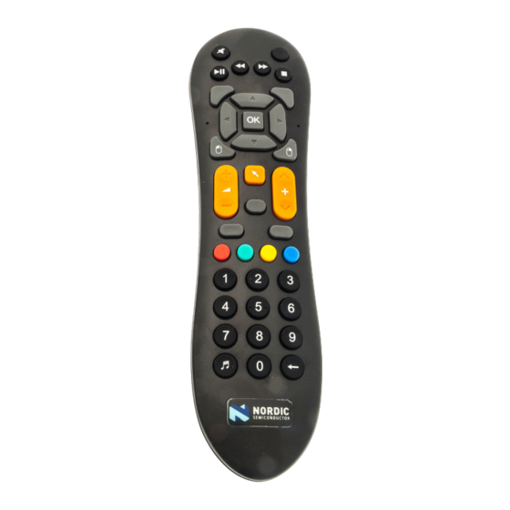
The product example contains all the hardware necessary for user interaction, including batteries. Figure 30: Smart Remote 3 nRF52 product example 6.1 Hardware figures: SR 3 product example The hardware drawings show both sides of the SR 3 product example board (PCA20023). Page 43 Doc. ID 4374_139 v1.1... -
Page 44: Block Diagram
Figure 31: SR 3 product example board (PCA20023), front side Figure 32: SR 3 product example board (PCA20023), back side 6.2 Block diagram The block diagram illustrates Smart Remote 3 DK product example functional architecture. Page 44 Doc. ID 4374_139 v1.1... -
Page 45: Design Description
Figure 33: Block diagram 6.3 Design description This chapter contains details about the hardware blocks on the Smart Remote 3 for nRF52 product example. 6.3.1 I/O usage The nRF52832-QFAA has 32 generic I/Os available. All I/Os are used in this design and are organized as shown in table below. -
Page 46: Keypad Matrix
6 Hardware description: Smart Remote 3 nRF52 product example Label Description P0.15 I2C_CLK Two-wire 1 master clock P0.16 KEYIN_0 Input from keypad row 0 P0.17 KEYIN_1 Input from keypad row 1 P0.18 KEYIN_2 Input from keypad row 2 P0.19 KEYIN_4 Input from keypad row 4 P0.20... -
Page 47: Low-Power Accelerometer Circuit
6 Hardware description: Smart Remote 3 nRF52 product example KEYIN_0 Green Yellow Blue KEYIN_1 V_Down Mute C_Down V_Up Back C_Up KEYIN_2 Menu Down Exit Left Right KEYIN_3 Power KEYIN_4 Figure 34: Keypad matrix 6.3.3 Low-power accelerometer circuit To obtain low power consumption and long battery lifetime, a low-power three-axis accelerometer (U7) has been added to the remote control. -
Page 48: Motion Tracking Device
N.C. Figure 35: Accelerometer circuit The accelerometer has I C outputs and can detect motion on 3 axes. The sensitivity is configurable to ±2 g/±4 g/±8 g/±16 g. 6.3.4 Motion tracking device For advanced features, the remote control has a three-axis gyro integrated with a three-axis accelerometer (U6). -
Page 49: Power Supply
C, there are four solder bridges that you need to change. SB7 and SB8 have to be soldered and SB5 and SB6 have to be cut. This circuit is a ±250°/sec/±500°/sec/±1000°/sec/±2000°/sec selectable 3-axis gyro and a ±2 g/±4 g/±8 g/±16 g selectable three-axis accelerometer. -
Page 50: Programming Interface
Figure 37: Battery schematic There is a power switch on the Smart Remote 3 that is connected to most of the circuits. The nRF chip controls the two transistors, which will turn on or off power to the microphones and to the motion tracking device. See Figure 38: Power on/off switch schematic on page 50. -
Page 51: Digital Microphones
No connection 6.3.7 Digital microphones The Smart Remote 3 product example is equipped with two digital output PDM microphones. The microphones are configured so they can be used to sample stereo audio, but are by default set to mono audio. The microphones are by default disconnected from the power supply and the interface connectors. To... -
Page 52: Matching Network
6 Hardware description: Smart Remote 3 nRF52 product example VIO_PDM MIC_CLK MIC_CLK 600R/0.5A 100R SB10 MIC_DOUT MIC_DOUT DOUT MP34DB02 SB11 10nF 10µF 15pF 15pF 600R/0.5A 100R DOUT MP34DB02 10nF 10µF 15pF 15pF Figure 40: Digital microphones schematic 6.3.8 Matching network The matching network is made up of discrete components and the impedance is tuned to 50 Ω. -
Page 53: Infrared Emitter/Receiver
6 Hardware description: Smart Remote 3 nRF52 product example The NFC antenna must be connected to P4, to enable the NFC feature of the smart remote. 330pF P0.10/NFC2 P0.09/NFC1 WCON-5140-5-XX 330pF Figure 42: NFC connector schematic 6.3.11 Infrared emitter/receiver Infrared emitter and receiver circuitry. -
Page 54: Schematics, Bill Of Materials, Pcb Layout Files, Production Files
6.3.13 Schematics, bill of materials, PCB layout files, production files Hardware files for the Smart Remote 3 nRF52 product example are available in a zip package. The hardware files for the Smart Remote 3 nRF52 product example are located in the following folder in the hardware files zip package:... - Page 55 6 Hardware description: Smart Remote 3 nRF52 product example Electrical specifications nRF52 product example Comments/conditions PCA20018 Rev 1.1.0/Typical value Connected idle 18 μA Typical wakeup latency (from idle to data ready to be sent) 20 ms Idle - Disconnected (motion 12 μA...
-
Page 56: Chapter 7: Firmware Update Of Smart Remote 3
Chapter 7 Firmware update of Smart Remote 3 You can update firmware using nRFgo Studio. This guidance covers some basic steps. More details about the firmware update procedure can be found in the firmware documentation. If you are programming the DK add-on, the nRF52 DK has the SEGGER J-Link built in and can be used through the USB cable. -
Page 57: Selecting A Board To Program
If you are using this Nordic firmware mentioned above, follow the steps below to program complete firmware onto the chip. If you are using your own firmware, see the firmware documentation available via the Smart Remote installer, section OTA-DFU - Generating your own packages. - Page 58 Turn on and pair with Ubuntu on page 13. 3. In the Device Manager pane, select the board to program. 4. Select the Segger ID matching the nRF52 DK connected to the product example. 5. Select the Program Application tab.
-
Page 59: Legal Notices
Nordic Semiconductor ASA customers using or selling these products for use in such applications do so at their own risk and agree to fully indemnify Nordic Semiconductor ASA for any damages resulting from such improper use or sale. - Page 60 All rights reserved. Reproduction in whole or in part is prohibited without the prior written permission of the copyright holder.
Need help?
Do you have a question about the 3 and is the answer not in the manual?
Questions and answers