Table of Contents
Advertisement
Quick Links
Advertisement
Table of Contents

Summary of Contents for Gelec ALLS6000
- Page 1 ANALOG LIQUID LEVEL SENSOR ALLS6000 INDUSTRIAL ELECTRONICS...
- Page 2 User’s & Technical Manual – ANALOG LIQUID LEVEL SENSOR ALLS6000 GELEC Industrial Electronics PAGE 2...
-
Page 3: Table Of Contents
PRECAUTIONS! ....................................4 MANUFACTURER’S WARRANTY, GENERAL TERMS AND CONDITIONS ..............5 DISPOSAL OF OLD ELECTRICAL & ELECTRONIC EQUIPMENT ..................6 ANALOG LIQUID LEVEL SENSOR ALLS6000 .......................... 7 GENERAL DESCRIPTION ................................8 ALLS6000 VERSIONS AND OPTIONAL PARTS ........................9 CONTROL UNIT ALLS6000 ................................. 11 PNEUMATIC SECTION ................................. -
Page 4: Precautions
ANALOG LIQUID LEVEL SENSOR ALLS6000 PRECAUTIONS! There are no serviceable parts inside the ALLS6000 unit. Not to be opened by any unauthorized person. All repairs to the device must be carried out by the manufacturer. Improper handling may result in serious personal injury and considerable material damage. -
Page 5: Manufacturer's Warranty, General Terms And Conditions
Any defect caused by modification, alteration, abuse, misuse or incorrect installation. Any defect of the product caused by improper repair by third party other than GELEC and GELEC's authorized distributors. Any incompatibility of the products with subsequent technical innovations or ... -
Page 6: Disposal Of Old Electrical & Electronic Equipment
User’s & Technical Manual – ANALOG LIQUID LEVEL SENSOR ALLS6000 DISPOSAL OF OLD ELECTRICAL & ELECTRONIC EQUIPMENT - Applicable through the EU and other European countries with separate collection programs - This symbol, found on your product, indicates that this should not be treated as household waste when you wish to dispose it. -
Page 7: Analog Liquid Level Sensor Alls6000
In order to ensure the best performance and effective use of the ALLS6000, we recommend that you read the information in this manual carefully and follow the instructions contained. -
Page 8: General Description
ANALOG LIQUID LEVEL SENSOR ALLS6000 GENERAL DESCRIPTION The ALLS6000 is a programmable electronic device used for liquid level control between a desirable region, in open tanks of height from 10 cm up to 500 cm, with analog sensor and digital output. Its operation is based on the measurement of the hydrostatic pressure of liquids. -
Page 9: Alls6000 Versions And Optional Parts
User’s & Technical Manual – ANALOG LIQUID LEVEL SENSOR ALLS6000 ALLS6000 VERSIONS AND OPTIONAL PARTS ALLS6000-S1 - STANDARD VERSION ● Mounted potentiometer for level adjustment ● 10kPa air pressure sensor Pre-calibrated High Level at 100 cm of clear water ●... - Page 10 User’s & Technical Manual – ANALOG LIQUID LEVEL SENSOR ALLS6000 - OPTIONAL PARTS - Air Pressure Regulator b ar 2 .5 fig. 3 Air Pump 10kPa PUMP GCP IP5000 TYPE P.S. 5V DC / 1.25W 1 2 3 4 5 6 7 8 9 10 1112...
-
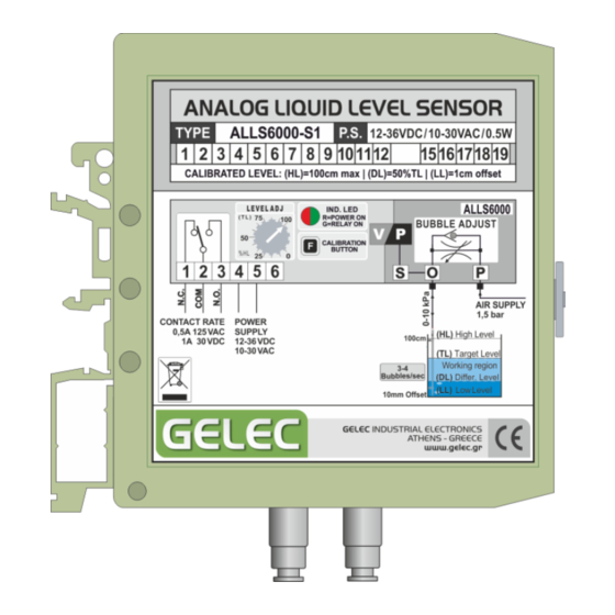
Page 11: Control Unit Alls6000
User’s & Technical Manual – ANALOG LIQUID LEVEL SENSOR ALLS6000 CONTROL UNIT ALLS6000 The ALLS6000 is a complete unit with built-in electric connection terminals, electronic board, air flow regulator, adjusting level knobs, a calibration button and air pipe connectors, in light green box, suitable for electronic devices, and DIN rail mounting. - Page 12 10 The unit must not be installed in height lower than the (HL). AIR PIPE CONNECTIONS At the bottom of the ALLS6000 there are 2 pipe connectors of 4-6 mm. Polyurethane or nylon pipes are suitable for these connectors.
- Page 13 3-4 bubbles/sec. AIR GAUGE SENSOR The ALLS6000 has a single, monolithic silicon diaphragm, piezoresistive strain gauge sensor chip, providing a highly accurate and linear output directly proportional to the applied pressure. On-Chip Temperature Compensated & Calibrated, this Silicon Pressure Sensor is laser trimmed for precise span and offset, bias equalized with the Atmospheric pressure.
-
Page 14: Electrical Section
ANALOG LIQUID LEVEL SENSOR ALLS6000 ELECTRICAL SECTION POWER SUPPLY (Terminals #4 - #5) The ALLS6000 includes an integrated power supply circuit. The maximum power consumption is approximately 0.5W in total operation, with all indicators and relay activated. Connect the power source with the terminals (4) and (5). The polarity is not important, as the internal power circuit includes electronic components for non-polarity connection. - Page 15 User’s & Technical Manual – ANALOG LIQUID LEVEL SENSOR ALLS6000 INDICATION LED The multicolour led at the front of the device the ability to know: If the device is powered (red colour). If relay contact is activated (green colour).
-
Page 16: Operating Philosophy - Level Description
ANALOG LIQUID LEVEL SENSOR ALLS6000 10. OPERATING PHILOSOPHY – LEVEL DESCRIPTION The ALLS6000 operating philosophy is based on a desirable working region and four critical liquid levels (fig. 14), which can be calibrated from the user to meet his application needs. The levels and their functionality are described below. - Page 17 User’s & Technical Manual – ANALOG LIQUID LEVEL SENSOR ALLS6000 The user can program the (DL) at a desirable level following the calibration process, without changing the other two level values. The Differential Level (DL) you select each time is stored in the unit’s memory as a percentage of (HL).
- Page 18 Notice that with these example’s steps, for every (TL) you select with the potentiometer, the (DL) will be 12,5% less. PRESELECTED VALUES The standard version ALLS6000-S1 can control the liquid level in tanks with height from 10cm to 100cm and has the below preselected values and parameters. ...
-
Page 19: Level Calibration Procedure
User’s & Technical Manual – ANALOG LIQUID LEVEL SENSOR ALLS6000 LEVEL CALIBRATION PROCEDURE With this procedure you can calibrate the device to store the required parameters, in order to function according to the needs of your application. For each level calibration follow the appropriate steps. -
Page 20: Filling / Draining Operating Modes
User’s & Technical Manual – ANALOG LIQUID LEVEL SENSOR ALLS6000 (DL) Differential Level Calibration Fill the tank up to the desirable differential level (e.g. • to the 70% of the (HL)) fig.17 Press and hold the button until the led starts flashing. - Page 21 20 OPERATING MODE SELECTION (F/D) You can see the mode that the ALLS6000 unit operates by the flashing colour of the LED just after the device power supply. According to the preprogrammed operating mode, the led flashes for three seconds with the corresponding color.
-
Page 22: Installation
Have the unit checked by a qualified service engineer before using it again. The ALLS6000 is composed of an electronic board and a plastic box suitable for electrical and electronic devices. At the rear there is a clip for the mounting. The unit is made to be installed inside an electrical control panel, placed on a mounting rail of Ω... -
Page 23: Electrical Circuit Diagram
(24-12AWG) (stranded with ferrule or plastic sleeve up to 0.75mm ) stripped over 10mm length. fig. 23 Always follow the instructions given by the manufacturer and use the ALLS6000 according to its specifications. 14. ELECTRICAL CIRCUIT DIAGRAM fig. 24 GELEC Industrial Electronics PAGE 23... -
Page 24: Air Circuit Diagram
User’s & Technical Manual – ANALOG LIQUID LEVEL SENSOR ALLS6000 15. AIR CIRCUIT DIAGRAM fig. 25 16. DIMENSIONS GELEC Industrial Electronics PAGE 24... -
Page 25: Technical Specifications
User’s & Technical Manual – ANALOG LIQUID LEVEL SENSOR ALLS6000 17. TECHNICAL SPECIFICATIONS TECHNICAL SPECIFICATIONS POWER SUPPLY: 10-30V AC / 12-36V DC AC FREQUENCY: 50 - 60 Hz ABSOLUTE SUPPLY LIMITS: 10-30V AC / 12-36V DC POWER CONSUMPTION: 0.5W max. - Page 26 User’s & Technical Manual – ANALOG LIQUID LEVEL SENSOR ALLS6000 CLAMPING SURFACE PROTECTION: Galvanic nickel or tin plating surface CLAMPING PARTS RESISTANCE: Electrolytic - rust - stress corrosion cracking IEC Rigid solid / 0.2 - 4.0mm CONNECTION DATA: IEC Flexible stranded / 0.2 - 2.5mm...
-
Page 27: Declaration Of Conformity
EN61000-6-4 ed. 2001 - EN61000-6-2 ed. 2001 - EN60950 ed. 2000 EEC NORMS The product “ANALOG LIQUID LEVEL SENSOR” type “ALLS6000” is designed and produced by the manufacturer “GELEC Co. Ltd” to be in compliance with the EEC norms applying to it. GELEC Industrial Electronics... - Page 28 User’s & Technical Manual – ANALOG LIQUID LEVEL SENSOR ALLS6000 INDUSTRIAL ELECTRONICS 4 Kikladon Str. Maroussi, Athens – Greece, GR-15125 Telephone: +30 210 6144074 - Fax: +30 210 6144074 - info@gelec.gr GELEC Industrial Electronics PAGE 28...
Need help?
Do you have a question about the ALLS6000 and is the answer not in the manual?
Questions and answers