Advertisement
092522 RevA
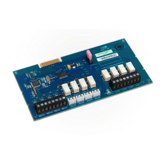
Input/Output Expander
for OmniLogic
Owner's Manual
Contents
Description............................2
Installation............................2
Configuration.........................6
HLIOEXPAND
Hayward Pool Products
620 Division Street, Elizabeth NJ 07207
www.hayward.com
USE ONLY HAYWARD GENUINE REPLACEMENT PARTS
Advertisement
Table of Contents

Summary of Contents for Hayward HLIOEXPAND
- Page 1 092522 RevA Input/Output Expander for OmniLogic Owner's Manual Contents Description......2 Installation......2 Configuration......6 HLIOEXPAND Hayward Pool Products 620 Division Street, Elizabeth NJ 07207 www.hayward.com USE ONLY HAYWARD GENUINE REPLACEMENT PARTS...
- Page 2 (1) This device may not cause harmful interference, and (2) this device must accept any interference received, including interference that may cause undesired operation. Changes or modifications not expressly approved by Hayward could void the user’s authority to operate this equipment.
- Page 3 This means a complete shutdown of power to the entire OmniLogic panel. Overview The HLIOEXPAND is design to slide between guide rails and insert into a dedicated slot on the Om- niLogic main board. Once inserted, the OmniLogic will discover the HLIOEXPAND and its inputs/ outputs can be configured within the OmniLogic's CONFIGURATION WIZARD.
- Page 4 Remove the OmniLogic deadfront to expose the main board and relays. Slide the HLIOEXPAND between the guide rails until it locks as shown below. In this position, the board will be sticking out from the enclosure allowing access to the wiring connections on the HLIOEXPAND.
- Page 5 After all connections have been made, use wire anchors and ties to secure the bundle of wires coming from the HLIOEXPAND. Two anchors (with adhesive back) and two nylon ties straps are provided. When determining a location to mount the anchors, be sure to position wiring below the deadfront and above the OmniLogic's main board.
- Page 6 Lock HLIOEXPAND into Position 2 With all the wires attached, slide the HLIOEXPAND between the guide rails until it locks into position 2 as shown below. If the board is difficult to slide, you may have to spread the guide rails slightly to release the board from position 1.
- Page 7 Configuration The HLIOEXPAND will be automatically discovered at power up and can be found in the CON- FIGURATION WIZARD. As you progress through the wizard, the four additional valve outputs, low voltage outputs, and temperature sensor inputs will all be displayed in their corresponding tables.
- Page 8 Hayward is a registered trademark and OmniLogic is a trademark of Hayward Industries, Inc. © 2013 Hayward Industries, Inc. All other trademarks not owned by Hayward are the property of their respective owners. Hayward is not in any way affiliated with or endorsed by those third parties.
Need help?
Do you have a question about the HLIOEXPAND and is the answer not in the manual?
Questions and answers