Table of Contents
Advertisement
Quick Links
Advertisement
Table of Contents

Subscribe to Our Youtube Channel
Related Manuals for Globalstar STX3


Summary of Contents for Globalstar STX3
- Page 1 STX3 DEVELOPMENT KIT WITH BLE TECHNOLOGY USER MANUAL 9150-0137-01 R-2...
-
Page 2: Table Of Contents
RADIO ASTRONOMY SITE AVOIDANCE .......................18 REGULATORY NOTICES ............................18 APPENDIX A – STX3 DEVELOPMENT KIT SCHEMATIC ..............I APPENDIX B – STX3 DEVELOPMENT KIT BILL OF MATERIAL LISTS ..........X TRANSMITTER BOARD BILL OF MATERIAL ......................X MAIN BOARD BILL OF MATERIAL ........................XI... -
Page 3: Introduction
STX3 Development Kit with BLE, hereby referred to as the Dev Kit. This document is intended to be used by engineers and technical management and assumes a general knowledge of basic engineering practices by the user. -
Page 4: Description
FTP host or HTTP host where the user will interpret the data for further processing. The STX3 is a surface mount module and it is mounted on the bottom side of the Transmitter board just under the Taoglas antenna. -
Page 5: Application
DESIGN DETAILS The Dev Kit design is a basic implementation of the STX3 module with a power source (host computer), a USB interface, user LEDs and buttons and a few peripheral sensors. The Dev Kit is a robust extension of the Reference Design described in the STX3 User Manual. -
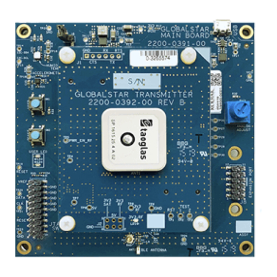
Page 6: Location Of The Features On The Dev Kit
Green and Red Indicator LED’s connected to processor JTAG(SWD) programming header for Nordic processor BLE chip antenna Green LED indicates when RF power supply is enabled. LED is only ON during STX3 transmission Expansion Header connected to processor Analog potentiometer USB connector, for applying power and serial terminal interface Label with ESN number. -
Page 7: Dev Kit Schematic
Main board. Please note the 3.3V voltage does not supply power to the RF transmitter of the STX3 module on the Transmitter board. All the circuitry on this page is... -
Page 8: Dev Kit Component Location
DEV KIT COMPONENT LOCATION Figure 2 - STX3 Dev Kit Component Location - Top Side of PCB Figure 3 - STX3 Dev Kit Component Locations - Bottom Side of PCB Table 1 - STX3 Dev Kit Operating Conditions & Parameters... -
Page 9: Setting Up The Dev Kit
Globalstar provides a free smartphone App that allows BLE communication with the Dev Kit. The app is available on the Apple App Store for iOS and Google App Store for Android. Search either app store for Globalstar and locate the one named STX3DK BLE. -
Page 10: Quick Test Of Dev Kit Operation
LED(LD1) on the Transmitter board will turn on for approximately 1 second and red LED on the main board will stay on. The STX3 is transmitting when this green LED is on. The STX3 module will transmit the same test message packet 3 times with a random delay between messages of 5-10 minutes. - Page 11 – The maximum burst interval If no arguments are used, then command 0x07 is issued to query the current setup state. Uses the serial command format to send the command 0x09 to return the STX3 Query HW Version hardware hardware version.
-
Page 12: Using The Stx3 Dk-Ble Smartphone App With The Dev Kit
USING THE STX3 DK-BLE SMARTPHONE APP WITH THE DEV KIT After installing the STX3DK-BLE smartphone app on your Android or iPhone device, you will need to have the Dev Kit powered before running the STX3DK-BLE app. The smartphone app will start up and begin scanning over Bluetooth, searching for Dev Kits within BLE range. - Page 13 Pressing Update button will update the Dev Kit’s temperature and humidity readings in real time. The STX3DK-BLE app communicates with the STX3 module in the same manner as if the Send Data command was issued from the serial command interface. Data values can be entered in the “Send Data Command” box. The value entered must be hexadecimal digits and correlate to the payload of the STX3’s Send Data command.
-
Page 14: Summary Of Stx3 Commands
SUMMARY OF STX3 COMMANDS Below is a table that summarizes the commands that may be sent to the STX3 using either the serial interface or the smartphone app. For detailed information of individual commands, refer to the STX3 User Manual, Section 5.2 Serial Packet Mode. -
Page 15: Hardware Description
There are two separate power domains on the STX3 module, one pin for the low power digital IO (VDIG pin). The second power input is dedicated to the RF transmitter (VRF pin) circuitry integrated in the STX3 module, and has a higher current demand at short bursts. -
Page 16: Dev Kit Power Circuitry
• STX3 RF Power Supply - The RF power supply is dedicated to the VRF pin on the STX3 module. The power supply is enabled and disabled by the STX3 module. This is a buck/boost supply and is used in a buck (step- down) configuration on the Dev Kit. -
Page 17: Sensors
SENSORS • Temperature/Humidity - This is a Silicon Labs (manufacturer part number Si7020-A20) sensor that integrates the temperature and humidity monitoring. The sensor is an I2C slave device connected to the Nordic processor. The sensor has a protective white cover on the top part of the package. The white cover should NOT be removed as it protects the sensor element from moisture. -
Page 18: Usb Interface
The Dev Kit includes a total of 39 test points spread across the Transmitter and Main boards. Many of the test points are connected to digital signals on the processor and STX3 module. There is also an array of test points that support monitoring of voltages and options for monitoring current. -
Page 19: References
A set of tools for testing Bluetooth Low Energy products. Nordic has versions Nordic nRF Connect for iOS, Android, and the PC. A terminal program that can be used to interact with the STX3 DK - BLE PuTTY board - https://www.putty.org/... -
Page 20: Regulatory Approval
FCC or other regulatory agencies. Users are responsible for compliance with all international, national, state, and local laws, rules, and regulations that apply to the handling or use of the STX3 Dev Kit by a user or the user’s employees, affiliates, contractors, representatives, agents, or designees. This includes interference with any radio communications. - Page 21 The STX3 module has been labeled with its own FCC and Industry Canada (IC) ID numbers, and if the FCC/IC ID numbers are not visible when the module is installed inside another device, then the outside of the finished product...
-
Page 22: Appendix A - Stx3 Development Kit Schematic
APPENDIX A – STX3 DEVELOPMENT KIT SCHEMATIC... - Page 29 VIII...
-
Page 31: Appendix B - Stx3 Development Kit Bill Of Material Lists
APPENDIX B – STX3 DEVELOPMENT KIT BILL OF MATERIAL LISTS TRANSMITTER BOARD BILL OF MATERIAL... -
Page 32: Main Board Bill Of Material
MAIN BOARD BILL OF MATERIAL...
Need help?
Do you have a question about the STX3 and is the answer not in the manual?
Questions and answers