Table of Contents
Advertisement
Quick Links
Product Information
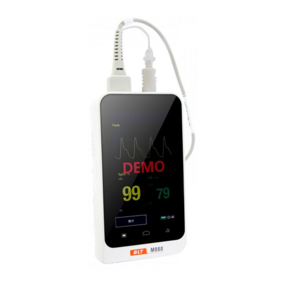
Product Model: M880
Product Name: Patient monitor
Manufacturer: Guangdong Biolight Meditech Co., Ltd.
After Service Contact Information:
Address:
No.2
Innovation Coast, Hi-tech Zone, Zhuhai ,
P.R.China
Fax: +86-756-3399919
Postcode: 519085
Toll-free consultation hot line: +86-400-8818-233
Revision History
This manual has a revision number. This revision
number changes whenever the manual is updated due to
software or technical specification change. Contents of this
manual are subject to change without prior notice.
Document No.: J/M880-I-005
Revision number: V1.0
Release time: Oct.2016
Copyright © 2016 Guangdong Biolight Meditech Co., Ltd.
All rights reserved.
Innovation
First
Road,
Technical
Advertisement
Table of Contents

Summary of Contents for BLT M880
- Page 1 Product Information Product Model: M880 Product Name: Patient monitor Manufacturer: Guangdong Biolight Meditech Co., Ltd. After Service Contact Information: Address: No.2 Innovation First Road, Technical Innovation Coast, Hi-tech Zone, Zhuhai , P.R.China Fax: +86-756-3399919 Postcode: 519085 Toll-free consultation hot line: +86-400-8818-233 Revision History This manual has a revision number.
- Page 2 Statement Manufacturer holds the copyright of this manual, and we are also entitled to deal with this manual as confidential files. This manual is only used for operation, maintenance and service of product, someone else can not publish the manual. This manual contains exclusive information protected by copyright laws and we reserve its copyright.
- Page 3 About this manual This manual contains the instructions necessary to operate the product safely and in accordance with its function and intended use. Observance of this manual is a prerequisite for proper product performance and correct operation and ensures patient and operator safety. This manual is based on the maximum configuration and therefore some contents may not apply to your product.
- Page 4 Signs in this manual: Warning: Indicates a potential hazard or unsafe practice that, if not avoided, will result in death or serious injury. Caution: Indicates a potential hazard or unsafe practice that, if not avoided, could result in minor personal injury or product/property damage. Note: Provides application tips or other useful information to ensure that you get the most from your product.
-
Page 5: Table Of Contents
Contents Chapter 1 General Introduction ........... 1-1 Intended Use .............. 1-1 Main Unit ..............1-1 Display Views ............1-6 Chapter 2 Safety ..............2-1 Safety Information ............. 2-1 Explanation of Symbols .......... - Page 6 Alarm Categories ............4-1 Alarm Levels ............. 4-2 Alarm Indicators ............4-3 Alarm Status Symbol ..........4-6 Alarm Tone Configuration ........4-6 Pausing Alarms ............4-7 Shutting off the Alarm Volume ........
- Page 7 Monitoring Procedure ..........6-4 SpO2 Display ............. 6-5 PR Display ..............6-6 Setting SpO2 .............. 6-7 Setting Desat Limit ............ 6-8 Chapter 7 Trend Review ............7-1 Introduction ...............
- Page 8 Appendix A Product Specifications ......... 1 A.1 Safety Specifications ............. 1 A.2 Physical Specifications ..........1 A.3 Environmental Specifications........2 A.4 Charging Specifications ..........2 A.5 Hardware Specifications ..........3 A.6 Data Storage ..............4 ...
-
Page 9: Chapter 1 General Introduction
Patient Monitor User’s Manual Chapter 1 General Introduction 1.1 Intended Use M880 patient monitor is intended for continuously monitoring or spot checking of CO2, RR, SpO2 and PR signals of single adult, pediatric and neonatal patient. This device can be used in institutions or units with health care capability. - Page 10 Pati ient Monitor User’s Manual -1 Front View of the Monitor Fig 1- Alarm indicat ing lamp When an alarm m occurs, this lamp will light up as defined below: High level alarm: the lamp quickly flashes re Medium le evel alarm: the lamp slowly flashes s yellow.
- Page 11 Patient Monitor User’s Manual The device uses resistive touchscreen, using stylus or fingernail will improve sensitivity. Alarm pause button It can pause the alarm for 120s when alarm volume is Pressing it can change the alarm message to prompt message when “Sensor off” alarm happens. Main interface button Press this button to return to main interface when it is on menu setting.
- Page 12 Pati ient Monitor User’s Manual Fig 1- -2 Rear View of the Monitor 1.2.3 Side View Topside:...
- Page 13 Pati ient Monitor User’s Manual Downside: Rightside: g 1-3 Side View of the Monitor CO2 connecto SpO2 probe co onnector Micro USB co onnector Connect with power adapter. Export data to o computer. Shortcut key Press this butt ton to start or pause the CO2 meas surement.
-
Page 14: Display Views
Patient Monitor User’s Manual Press it about two seconds to turn off when the monitor is on the condition of working. Calibration of touch screen Press shortcut key firstly and press power button and immediately loose shortcut key, click the center of appearing point on screen. - Page 15 Patient Monitor User’s Manual 1.3.1 Multi-Parameter Display Mode Fig 1-4 Multif-parameter Display Mode Patient ID No.: Click and set patient information, its range from 1 to 96. SpO2 parameter area: The current SpO2 and its higher and lower alarm limits are shown in the area. SpO2 waveform area: The waveform shown in the area is current SpO volume curve.
- Page 16 Patient Monitor User’s Manual CO2 parameter area: The current CO2 and its higher and lower alarm limits are shown in the area CO2waveform area: CO2 waveform is shown in the area. Physiological alarm area: Current physiological alarm information is shown in the area. Technical alarm and prompt information area: Current technical alarm and prompt information are shown in the area.
- Page 17 Patient Monitor User’s Manual 1.3.2 SpO2 Display mode Fig 1-5 SpO2 Display Mode SpO2 waveform area: The waveform shown in the area is current SpO volume curve. parameter area: The values shown in the area are current SpO value and its higher and lower alarm limits. PR parameter area: The values shown in the area are current PR value and its upper and lower alarm limits.
- Page 18 Patient Monitor User’s Manual 1.3.3 CO2 Waveform Display Mode Fig 1-6 CO2 Display Mode CO2 waveform display area: Waveform shown in the area is current CO2 waveform 。 CO2 parameter area: The values shown in the area are current HR value and its higher and lower alarm limits. RR parameter area: The values shown in the area are current RR value and its higher and lower alarm limits.
-
Page 19: Chapter 2 Safety
Patient Monitor User’s Manual Chapter 2 Safety 2.1 Safety Information Warning: Explosion hazard: Do not use the monitor in the presence of flammable anesthetics mixture with air, oxygen, or hydrogen. When the monitor is in use, there should not be any great power appliances as high voltage cables, X-ray machine, ultrasound equipment and electrizer in use nearby. - Page 20 Patient Monitor User’s Manual Do not come into contact with the patient during defibrillation. Otherwise serious injury or death could result. When the monitor is connecting with high-frequency devices, sensors and cables should avoid touching high-frequency devices, in order to leakage current burns patient.
- Page 21 Patient Monitor User’s Manual degrade or contamination could occur. The service life of this monitor is five years. At the end of its service life, the product described in this manual, as well as its accessories, must be disposed of in compliance with the guidelines regulating the disposal of such products.
- Page 22 Patient Monitor User’s Manual unable to be connected to the AC power, the battery can be used to supply power, and at this time it is unnecessary to use the electrical wires, and the instrument can be switched on directly. The monitor can only monitor one patient at a time.
-
Page 23: Explanation Of Symbols
Pati ient Monitor User’s Manual This manual l describes all features and opti ions. Your monitor may y not have all of them. Explanat tion of Symbols Symbol Symbol Note Type C CF applied part, defibrillation prote ected The uni it displaying this symbol contains an F-Type isolated... - Page 24 Pati ient Monitor User’s Manual Alarm r reset QRS vo olume off Date of f manufacture Manufa acturer Serial n number Power b button Short fo or “Carbon dioxide” Short fo or “Respiratory Rate” Short fo or “Pulse Oxygen Saturation” Symbol l for the marking of electri ical and...
-
Page 25: Chapter 3 Basic Operations
Patient Monitor User’s Manual Chapter 3 Basic Operations 3.1 Unpacking and Checking Open the package. Parts are as follows in the package .Take out the monitor and its accessories. Parts Standard Optional Quantity CO2 nose sampling √ tube CO2 filter √... -
Page 26: Starting The Monitor
Patient Monitor User’s Manual following checks on the monitor including all connected modules. ——Check for any mechanical damage; ——Check for any incorrect connection of all the external cables and accessories Warning: If the monitor is mechanically damaged, or if it is not working properly, do not use it for any monitoring procedure on a patient. -
Page 27: Screen Brightness Setting
Patient Monitor User’s Manual 3.4 Screen Brightness Setting 【Menu】→【System】 ,click the right of 【Brightness】 , you can set the screen brightness to a value between 1to 5, choose the low level brightness to save power. Caution: If the monitor is used outdoors or the ambient light is strong, set the screen brightness to a higher level. -
Page 28: Patient Information Setting
Patient Monitor User’s Manual Select 【 Date Format 】 , it can be set to 【 Year/Month/Day 】 、 【 Month/Day/Year 】 or 【Day/Month/Year】. Select 【 Time Format】, it can be set to【24h】or【12h】. Set the current date and time and select【OK】to confirm 3.7 Patient Information Setting Please select patient information correctly before measuring, Click 【ID】... -
Page 29: Demo Mode Setting
Patient Monitor User’s Manual 3.8 Demo Mode Setting To enter the demo mode: Select 【Menu】→【System】→【Maintenance】→enter the required password. Click the right of 【Demo】to turn on. To exit the demo mode: Select 【Menu】→【System】→【Maintenance】→enter the required password. Click the right of 【Demo】to turn off. Caution: The Demo mode is for demonstration purpose only. -
Page 30: Checking The Version
Patient Monitor User’s Manual 3.10 Checking the Version Select【Menu】→【System】to check the version of the monitor . 3.11 Restoring the Factory Configuration If you have changed the system’s configuration and want to restore the factory configuration, follow this procedure: 1. Select【Menu】→【System】. 2. - Page 31 Patient Monitor User’s Manual 【System】→【Maintenance】, enter the required password, click the right of 【Auto power-off setting】, you can select “off”, “10min”, “30min”.
-
Page 32: Chapter 4 Alarm
Patient Monitor User’s Manual Chapter 4 Alarm Alarm refers to a prompt that is given by the monitor for medical personnel through visual, audible and other means when a vital sign appears abnormal or the monitor occurs technical problem. Note: The monitor generates all the audible and visual alarms through speaker, alarm lamp and screen. -
Page 33: Alarm Levels
Patient Monitor User’s Manual Technical alarms Technical alarms are triggered by a device malfunction or a patient data distortion due to improper operation or system problems. Technical alarm messages are displayed in the technical alarm area. Prompt messages As a matter of fact, prompt messages are not alarm messages. Apart from the physiological and technical alarm messages, the pulse monitor will show some messages telling the system status. -
Page 34: Alarm Indicators
Patient Monitor User’s Manual Indicate that the patent’s vital signs appear abnormal and an immediate treatment may be required. By severity, the monitor’s technical alarms can be classified into four categories: high level, medium level alarms, low level alarms and prompt message. Caution: The levels of technical alarms are predefined before the monitor leaves the factory and cannot be changed... - Page 35 Patient Monitor User’s Manual screen. Flashing numeric: The numeric of parameter in alarm flashes. Caution: For different alarm levels, the alarm lamp, alarm tone and alarm messages presented are different. 4.3.1. Alarm Tone The different level alarms are indicated by the system in following different audio ways: Alarm Audible prompt...
- Page 36 Patient Monitor User’s Manual following different visual ways: Alarm level Visual prompt High Alarm lamp flashes in red with 2 Hz. Medium Alarm lamp flashes in yellow with 0.5 Hz. Alarm lamp lights on in yellow without flashing. Caution: When multiple alarms of different levels occur at the same time, the monitor will select the alarm of highest level give visual and alarm indications.
- Page 37 Pati ient Monitor User’s Manual Medium level alarms: ** Low level alarm ms: * The system us ses different background colors for r the alarm message to ma tch the alarm level: High level alar rms: red Medium level alarms: yellow Low level alarm ms: yellow Prompt messag...
- Page 38 Pati ient Monitor User’s Manual Select 【Menu】 ce】, enter 】→【System】→【Maintenan the required passwor rd, select 【Machine Mainten.】 → → 【Alarm Alm.Vol.】, you can select “ Off, H Setup】→【Min.A High, Mid, Low”. Alarm volume e setting Select 【Menu】 ume】, you 】→【System】→【Alarm Volu can select from X to 4.
- Page 39 Pati ient Monitor User’s Manual 4.7 Shutting o off the Alarm Volume Set the 【Min.A lm.Vol.】 and【Alarm Volume】 to o 【off 】 to shut off the alarm volume. Then there will be a sym mbol shown in the alarm m status area. The alarm lamp and alarm messages are still a active after the alarm volume is...
-
Page 40: Alarm Reset
Pati ient Monitor User’s Manual 4.8 Alarm Re Select 【Menu 】→【System】→【Maintenanc ce】→enter the required passwor rd, select 【Machine Mainten.】 → → 【Alarm Setup】. You can turn on alarm reset. Alarm res set will be displayed on the inte erface of system. Select 【Menu u】→【System】→【Alarm rese et】. - Page 41 Patient Monitor User’s Manual Identify alarming parameter and alarm category. Identify the cause of the alarm. Silence the alarm, if necessary. When cause of alarm has been over, check that the alarm system is working properly. You will find the alarm message for the individual parameter in Appendix C Alarm message.
-
Page 42: Chapter 5 Measuring Co2
Patient Monitor User’s Manual Chapter 5 Measuring CO2 5.1 Introduction The monitor adopts infrared absorption technology to measure the carbon dioxide (CO ) concentration in the breathing airway of patient. Because CO molecule can absorb infrared light of special wavelength, and the amount of absorbed infrared light directly relates to the concentration of CO therefore while the infrared light radiated from the infrared light source passing through the... -
Page 43: Monitoring Procedure
Patient Monitor User’s Manual manner that may cause entanglement or strangulation. Performance is not guaranteed if an item labeled as single patient use is reused. Monitor the CO waveform (Capnogram). If you see changes or abnormal appearance check the sampling tube. - Page 44 Patient Monitor User’s Manual CO2 filter with 3-way joint of the loop of anesthetic machine by sampling tube, or to directly connect patient’s nose by the hose. Fig 5-1-1 Connection of Sampling and Filter...
- Page 45 Pati ient Monitor User’s Manual Fig 5-1-2 Conne ection of Sampling with 3-way jo oint or patient’s nose Note: Inserting th he sampling tube into the receptacle automatically y starts the sampling pump. R Removal of the sampling tube turns the sample pump off To remove th he CO2 filter from CO2 connec ctor, press...
- Page 46 Pati ient Monitor User’s Manual Connect CO2 2 filter into CO2 connector and r rotate CO2 filter closewis Connect samp pling tube into CO2 filter. If the e sampling tube is occlud ded or damaged, perform a “Check k sampling line”...
-
Page 47: Co2 Display
Patient Monitor User’s Manual 5.4 CO2 Display CO2 parameter display Fig 5-2 CO2 Display 1.CO2 label 2.CO2 high alarm limit 3. CO2 low alarm limit 4. CO2 value 5. CO2 unit CO2 waveform display Fig 5-3 CO2 Waveform Display... -
Page 48: Respiratory Rate
Patient Monitor User’s Manual 5.5 Respiratory Rate Fig 5-4 RR Display 1. RR label 2. RR higr alarm limit 3. RR low alarm limit 4. RR value 5. RR unit 5.6 Setting CO2 Select 【Menu】→【CO2 Setup】, enter into CO2 setup interface. - Page 49 Pati ient Monitor User’s Manual Fig 5-5 CO2 Setup Interface 5.6.1 Setting CO O2 and RR Alarm Click the right of 【Alarm】, you can set CO O2 and RR Alarm , you can sele ect “Mid, High”. 5.6.2 Setting CO O2 and RR Alarm Limits Click the right of f 【Uplimit】...
- Page 50 Patient Monitor User’s Manual alarm limit should greater than the lower one. 5.6.3 Setting CO2 Scan Speed Select scan speed of CO2 waveform. Click the right of 【Speed】, you can select “6.25 mm/s、12.5mm/s, 25 mm/s”. 5.6.4 Setting CO2 Unit Click the right of 【CO2 Unit】 , you can select “mmHg、 %、 kPa”.
-
Page 51: Co2 Zero
Patient Monitor User’s Manual 5.7 CO2 Zero While zeroing is recommended the first time the monitor is connected to the filter, it is only absolutely necessary when the message “Zero Required” is displayed. Follow these steps: Ensure that the sampling tube is not connected to the patient or close to any source of CO2 (including the patient's, your own, exhaled breath and ventilator exhaust valves). -
Page 52: Calibration
Patient Monitor User’s Manual allows any CO2 remaining in the sampling tube to dissipate before zeroing. Do not attempt to zero the monitor while the sampling tube is in the patient’s airway. Do not attempt zeroing if the temperature is not stable. Zeroing with CO2 in sampling tube can lead to inaccurate measurements or other error conditions. -
Page 53: Removing Exhaust Gases From The System
Patient Monitor User’s Manual ——After the latest calibration, atmospheric pressure or height above sea level varies evidently. Caution: User may only calibrate the device under the instruction technical personnel authorized manufacturer. Moreover, incorrect calibrating procedure may result in incorrect reading. 5.9 Removing Exhaust Gases from the System Warning:... -
Page 54: Chapter 6 Measuring Spo2
Patient Monitor User’s Manual Chapter 6 Measuring SpO2 6.1 Introduction The measurement of oxygen saturation of arterial blood (also known as pulse oxygen saturation, usually shortened as ) adopts the principles of light spectra and volume tracing. The LED emits lights with two specific wavelengths, which are selectively absorbed oxygenated... -
Page 55: Safety Information
Patient Monitor User’s Manual 6.2 Safety Information Warning : Use only SpO2 sensors specified in this manual. Follow the SpO2 sensor’s instructions for use and adhere to all warnings and cautions. When a trend toward patient deoxygenation is indicated, blood samples should be analyzed by a laboratory co-oximeter to completely understand the patient’s conditions. - Page 56 Patient Monitor User’s Manual errors, and certain patient conditions. See the appropriate sections of this manual for specific safety information. Check the SpO2 sensor and its package for any sign of damage before use. Do not use the sensor if any damage is detected.
-
Page 57: Monitoring Procedure
Patient Monitor User’s Manual self-examination alarm signal and the operator has to use SpO simulator for self-examination. 6.3 Monitoring Procedure 1. Selecting SpO Sensor Depending on the patient category, weight and application site, you can select the SpO sensor as required. 2. -
Page 58: Spo2 Display
Patient Monitor User’s Manual measurement results might be produced. When using finger sensor, make sure the nail faces to the light window. 6.4 SpO2 Display Parameter Display Fig 6-1 SpO Parameter 1. SpO label 2. High alarm limit of SpO 3. -
Page 59: Pr Display
Patient Monitor User’s Manual Waveform Display Fig 6-2 SpO Volume Curve 6.5 PR Display Fig 6-3 PR Display 1. PR label 2. High alarm limit of PR 3. Low alarm limit of PR 4. PR value 5. PR unit... - Page 60 Pati ient Monitor User’s Manual Caution: Dur ring the monitoring of HR and PR, displ laying of HR has priority. That is PR will be d displayed only when there isn’t HR moni itoring. 6.6 Setting Sp Select 【Menu】 】→【SpO2 Setup】, enter into S SpO2 Setup interface.
-
Page 61: Setting Spo2
Patient Monitor User’s Manual 6.6.1 Setting SpO2 Alarm Click the right of 【Alarm】 , you can set alarm level of SpO and PR, you can select “Mid, High” 6.6.2 Setting SpO2 Alarm Limits Click the right of 【Uplimit】 or 【Downlimit】 , you can set the SpO2 uplimit and downlimit. - Page 62 Patient Monitor User’s Manual the desat limit, a high physiological alarm will be trigged. Its setting is as follows. 1、 Select 【 Menu】 → 【System】 → 【Maintenance】 , enter the required password. 2、 Select 【Machine Mainten】→【SpO2 Setup】→【Desat limit】, click the right of 【Desat limit】to set its value.
-
Page 63: Chapter 7 Trend Review
Pati ient Monitor User’s Manual Chapter 7 Tr rend Review 7.1 Introducti Select 【Men u】→【Trend】to enter trend reviewing window. In the wind dow, you can review CO2, RR, Sp and PR data stored before. 7.2 Review In nterface Fig 7-1 Review Interface... -
Page 64: Review Setup
Pati ient Monitor User’s Manual If the trend da te is not only one page, you can turn pages by the next/return bu utton. 7.3 Review Se etup Click the right of 【ID】to select patient’s ID D, you can review patient’s tren d review by selecting different ID g 7-2 ID Review Interface Click the right of... - Page 65 Pati ient Monitor User’s Manual Fig 7-3 T The drop-down Window of “Mor re” You can set 【S Save time】, 【Delete】, 【De elete all】, n this interface. 【Transmission】in Save time: To o adjust recording time, you can select”10s, 30s, 1min, 2 m min, 5min, 10min”.
- Page 66 Patient Monitor User’s Manual monitor with the USB connector. After sending all the trend data, you can check them in the computer.
-
Page 67: Chapter 8 Battery
Pati ient Monitor User’s Manual Chapter 8 B attery 8.1 Introducti A rechargeable a and maintenance-free battery is de esigned for Patient Monitor, wh hich enables continuous working when AC power off. When r a lithiu um ion battery is used, the ba attery icon indicates the battery status as follows:... -
Page 68: Charging The Battery
Patient Monitor User’s Manual 8.2 Charging the Battery To charge the battery: Connect the Micro USB in power adapter, Connect the other connector of Micro USB in the monitor, and plug the adapter into the AC mains, The indicating lamp on the monitor is on to indicate that the battery is in charge, When the battery charging indicating lamp on the monitor turns off, the battery is fully charged. -
Page 69: Checking The Lithium Battery
Patient Monitor User’s Manual 2. Place the monitor in the charger stand and connect the AC mains. Allow the battery to be charged uninterruptedly for above 4 hours. 3. Remove the AC mains and allow the monitor to run from the battery until it shuts off. -
Page 70: Disposing Of The Batteries
Patient Monitor User’s Manual 8.5 Disposing of the Batteries Batteries that are damaged or depleted should be replaced and discarded properly. Dispose of used batteries according to local regulations. Warning: Do not disassemble batteries, or dispose of them in fire, or cause them to short circuit. They may ignite, explode, or leak, causing personal injury. -
Page 71: Chapter 9 Maintenance And Cleaning
Patient Monitor User’s Manual Chapter 9 Maintenance and Cleaning Introduction Keep your equipment and accessories free of dust and dirt. To avoid damage to the equipment, follow these rules: Always dilute according the manufacturer’s instructions or use lowest possible concentration. Do not immerse part of the equipment in the liquid. -
Page 72: Seasonal Safety Checking
Patient Monitor User’s Manual Caution: If you spill liquid into the equipment of accessories, connect you service personal or us. Seasonal Safety Checking Note: To ensure the performance and safety of equipment, it must be checked after using 1 year. When check the equipment, please contact professional technology engineers. - Page 73 Patient Monitor User’s Manual instructions for use. ④ Test the earth leakage current according IEC 60601-1 Limit: NC 500μA, SFC: 1000μA. ⑤ Test the enclosure leakage current according to IEC 60601-1: Limit: NC 100μA, SFC: 500μA. ⑥ Test the patient leakage current (normal operation) according IEC 60601-1 Limit: type CF: for a.c.: 10μA, for d.c.: 10μA.
-
Page 74: Cleaning The Monitor
Patient Monitor User’s Manual Cleaning the Monitor Common detergent and non-corrosive disinfectant used in hospital can be applied to clean monitor, however you must be aware that many kinds of detergents must be diluted prior to utilization, and please use it according to the instruction of detergent manufacturer. -
Page 75: Cleaning Spo2 Sensor
Patient Monitor User’s Manual 9.4 Cleaning SpO2 Sensor 1. The casing of the sensor and light tube can be cleaned with swab or non-velvet soft cloth dipped with medical alcohol. 2. The sensor cable can be cleaned or sterilized with Hydrogen Peroxide 3% or isopropyl alcohol 70%. -
Page 76: Chapter 10 Accessories
Patient Monitor User’s Manual Chapter 10 Accessories Warning: Use only accessories specified in this manual. Using other accessories may cause damage to the monitor. Disposable accessories are designed for single-patient use only. Reuse of them may cause a risk of contamination and affect the measurement accuracy. -
Page 77: Appendix A Product Specifications
Patient Monitor User’s Manual Appendix A Product Specifications A.1 Safety Specifications CFDA classification CE classification Type of protection against electric II, with internal power or shock external power device Degree of protection against electric shock Ordinary equipment, without Degree of protection against protection against hazards of hazards of explosion explosion... -
Page 78: Environmental Specifications
Patient Monitor User’s Manual A.3 Environmental Specifications Operating: 5℃ to +40℃; Temperature Storage: -20℃ to +55℃; Operating: 860hPa to 1060hPa; Atmospheric pressure Storage: 500hPa to 1060hPa; Operating: 15% to 85%(non condensing) Humidity Storage: 10% to 93%(non condensing) A.4 Charging Specifications A4.1 Charger Micro USB Charge, Data export... -
Page 79: Hardware Specifications
Patient Monitor User’s Manual A.5 Hardware Specifications A.5.1 Display Size 4.3inch Resolution 480*272 Touch Resistive touch Autorotation four direction Direction A.5.2 Indicating Lamp Alarm indicating 1(Yellow/Red), on the top of screen Battery charging 1(orange) indicating lamp When charged, it lights orange. When fully charged or not charged, it doesn’t light A.5.3 Audio Indicating ... -
Page 80: Data Storage
Patient Monitor User’s Manual 60601-1-8. Alarm pressure 45 dB to 85 dB, Testing place is 1 meter from the tone. A.5.4 Buttons Power button Turn on/off Start/Pause CO2 measurement Shortcut key Short press to achieve the above function, long press + power button to achieve calibration of LCD A.6 Data Storage The changing trends of physiological parameters will be... -
Page 81: Measurement Specifications
Patient Monitor User’s Manual 500 groups/patient can be stored (only Capacity data, no waveform). A.7 Measurement Specifications A.7.1 CO2 Specifications CO2 (Sidestream) Measureme Infrared spectrum nt Way Measureme 0—19.7%( 0-150mmHg or 0-20.0kPa ) nt Range 0%-5.3%(0mmHg-40mmHg),±0.3%(±2mm Hg); Accuracy 5.4%-9.2%(41mmHg-70mmHg), ±5% of reading;... - Page 82 0—19.7%( 0-150mmHg or 0-20.0kPa ) Range high/low limit can be adjusted continuously Alarm Blinking display of the data and parameters, Indication text prompts, Three levels of alarming: sound-light alarming, alarming with blinked data and parameters, and that with text prompts. A.7.2 BLT-SpO2 Measurement 0~100%...
- Page 83 Patient Monitor User’s Manual range Resolution Accuracy 70~100%:± 2% Alarm Select the high and low alarm limit of Sensor Pulse oximetry sensors contain LEDs that emit red light at a wavelength of approximately 660 nm and infrared light at a wavelength of approximately 905 The total optical output power of the sensor LEDs is less than 15 mW.
- Page 84 Patient Monitor User’s Manual Pitch Tone with Measurement 25 bpm ~250 bpm range resolution 1 bpm accuracy ±1% or ± 1 bpm, whichever is greater Alarm Select the high and low alarm limit of PR...
-
Page 85: Appendix B Factory Defaults
Patient Monitor User’s Manual Appendix B Factory Defaults This section lists the most important factory default settings. These settings can be adjusted and you can load the factory defaults if you need. B.1 Alarm Setup Alarm Setup Factory Default Alarm volume Medium Minimum alarm... -
Page 86: Co2 Setup
Patient Monitor User’s Manual B.3 CO2 Setup CO2 setup Adult Pediatric Neonate EtCO2 High Limit EtCO2 Low Limit Adult Pediatric Neonate RR High Limit RR Low Limit B.4 SpO2 Setup Setup Adult Pediatric Neonate SpO2 High Limit SpO2 Low Limit PR Setup Adult Pediatric... -
Page 87: Appendix C Alarm Message
Patient Monitor User’s Manual Appendix C Alarm Message This section lists some important alarm message. In the tables below, “*” means the alarm level is user-adjustable. C.1 Physiological Alarm SpO2 Cause Level Alarm Messages SpO2 Too High * High、 Medium A measurement has risen above the high alarm limit SpO2 Too Low *... -
Page 88: Technical Alarm
Patient Monitor User’s Manual weak to be analyzed. Cause Level Alarm Messages EtCO2 Too High A measurement has risen High、 above the high alarm limit Medium or fallen below the low EtCO2 Too Low * High、 alarm limit. Medium RR Too High High、... - Page 89 Patient Monitor User’s Manual Sensor Off The CO sensor detached the patient or the monitor. Communication Communication error or test Error model error. Battery Low The battery power is low. Medium Low Perf The signal detected is weak. Medium measurement CO2 measurement Over over range range, need verify zero...
-
Page 90: Prompt Message
Patient Monitor User’s Manual C.3 Prompt Message Message Cause Level searching Searching pulse sensor off sensor may be disconnected from the Prompt patient or the monitor. Message Zero in Progress Zeroing is in progress. sensor off Sensor dose not connect with monitor when the monitor is running. -
Page 91: Appendix D Emc
Patient Monitor User’s Manual Appendix D EMC... -
Page 92: Appendix E Warranty Registration Card
Card Thank you for purchasing products of BLT! Please complete this card and mail back to BLT Service Center in ZHUHAI within one week. If you need any support or the defects occur, please feel free to contact us by telephone or fax. - Page 93 Product name: Patient Monitor Product type: M880 Manufacturer: Guangdong Biolight Meditech Co., Ltd. Address: No.2 Innovation First Road, Technical Innovation Coast, Hi-tech Zone, Zhuhai, P.R.China Postcode: 519085 PN: 22-067-0006...
Need help?
Do you have a question about the M880 and is the answer not in the manual?
Questions and answers
Hello, if the lung image is flashing red what does this mean?
A flashing red lung image on the BLT M880 indicates a high-level physiological alarm.
This answer is automatically generated