
Subscribe to Our Youtube Channel
Summary of Contents for CowTech Ciclop 3D
- Page 1 CowTech Ciclop 3D Scanning Guide [Document subtitle] CowTech Engineering, LLC Big Timber, MT...
-
Page 2: Table Of Contents
CowTech Ciclop 3D Scanning Guide Introduction ......................... 2 Things to Have Before Starting..................3 Assembling the Hardware ......................... 3 Assembling the Electronics ........................3 Installing the Software ..........................6 How the 3D Scanner Works ..................7 Selecting an Object ...................... 8 Calibration ........................ -
Page 3: Introduction
CowTech Ciclop 3D Scanning Guide Introduction This guide was written for use with the CowTech Ciclop 3D Scanner, which began as a Kickstarter project in February 2016. The aim of this guide is to show you how to get the highest quality scans possible, and is based off our own experience with using the scanner. -
Page 4: Things To Have Before Starting
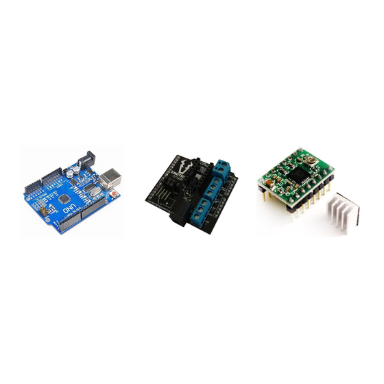
Assembling the Hardware You will need a fully assembled Ciclop. If you haven’t done so yet, please refer to the “downloads” section of the CowTech website for assembly instructions: http://www.cowtechengineering.com/downloads It is important to build the scanner in the order prescribed by the assembly instructions. - Page 5 Stepper Motor Driver is on top. It is essential to properly orient the boards. The CowTech logo on the CT Board should be oriented opposite from the USB and power plugs on the Uno Clone.
- Page 6 CowTech Ciclop 3D Scanning Guide Plugging in the Boards and Components Make sure to plug in the boards and components as shown in the picture below. It is possible to damage the Stepper Motor Driver if the boards are plugged in incorrectly. The blue connections on the right side of the board will require a flathead screwdriver to secure in place.
-
Page 7: Installing The Software
Horus version 0.2rc1. You can download Windows, Mac, or Ubuntu versions of Horus for free at the link below. Run the installer and follow the onscreen instructions. The installer may give you the option to install “FTDI Drivers” or “Arduino Drivers.” Neither are necessary to run the CowTech Ciclop 3D Scanner. -
Page 8: How The 3D Scanner Works
How the 3D Scanner Works The CowTech Ciclop can generate scans with or without a texture. A scan with texture will be colored like the object is, while a scan without texture will be the object’s geometry only. The Ciclop utilizes a camera, two lasers, and a spinning table to make scans. -
Page 9: Selecting An Object
CowTech Ciclop 3D Scanning Guide Selecting an Object Select an object suitable for scanning. The Ciclop uses red lasers to highlight sections of an object for the camera to record in 3D space. When selecting an object to 3D scan, it’s important that the object makes it easy for the camera to see the red lasers. -
Page 10: Calibration
CowTech Ciclop 3D Scanning Guide Calibration Calibration is the difference between a good scan and a bad scan. Follow all of the steps below to ensure that you get a good one. If you come across any further tips and tricks, please do share them with us on our FaceBook page! https://www.facebook.com/groups/564912093672675/... -
Page 11: Connecting The Camera
CowTech Ciclop 3D Scanning Guide Connecting the Camera Plug in the camera and press the Connect Icon on the top left corner of the screen. If all goes well, you will see live footage from the camera in the middle segment of the Scanning Workbench. If you’re having issues with this step, there are a number of possible... - Page 12 CowTech Ciclop 3D Scanning Guide Focus the lasers. The lasers have a small plastic lens on the end that focuses the beam into a line. Rotate it to make the line as thin and bright as possible. A thin laser makes it easier to capture fine detail.
-
Page 13: Using The Adjustment Workbench
CowTech Ciclop 3D Scanning Guide Rotate the table with your hands. You may notice that the lasers don’t hit as much of the object at certain angles. GOOD Adjust the position of the lasers or object to ensure good coverage. - Page 14 CowTech Ciclop 3D Scanning Guide to detect the calibration pattern. The Adjustment Workbench lets you adjust the camera’s settings separately for each task to maximize its ability to tell colors apart. Success is dependent on the lighting of the room.
- Page 15 CowTech Ciclop 3D Scanning Guide The more indirect the light is, the better. Direct light can cause glare on the slightly TOO BRIGHT (GLARE) reflective surface of the sticker, which makes the black squares in some areas indistinguishable from the white ones. The picture at right is an example of this.
- Page 16 CowTech Ciclop 3D Scanning Guide Fiddle with settings to get Horus to detect the pattern at as steep angle as possible. The picture at right is the result of modifying only the brightness, and gives a decent angle of detection. Generally, you want to be able to detect the pattern when displaced at least 45°...
- Page 17 CowTech Ciclop 3D Scanning Guide Calibration Segmentation Calibration segmentation covers all the settings that govern how Horus tells red laser light from other colors. Horus will show you which areas register as laser light with white highlights, while leaving everything else black. This is important during calibration, when Horus uses light from the lasers shining on the calibration pattern to orient the lasers and table in relation to the camera.
- Page 18 CowTech Ciclop 3D Scanning Guide Fiddle with the settings until only white squares are detected. It can be difficult to make it so that all of them show up with equal thickness. It’s fine if only two or three of the white squares show up on each laser.
- Page 19 CowTech Ciclop 3D Scanning Guide Scan Segmentation Put your object on the table. This step is just like Calibration Segmentation, except you use the object rather than the calibration pattern. Fiddle with the settings. Depending on the color of your object, they might be slightly different from those from Calibration Segmentation.
-
Page 20: Using The Calibration Workbench
CowTech Ciclop 3D Scanning Guide Saving the Adjustment Profile The settings you got from the previous steps can be saved and loaded for later. This is extremely useful as long as you have consistent lighting, as it saves you the trouble of fiddling with settings each time you’d like to scan. - Page 21 CowTech Ciclop 3D Scanning Guide Measure origin distance as accurately as possible. The origin distance is measured from the bottom edge of the feet of the calibration pattern to the top edge of the nearest square. We recommend using calipers if you have them. Input this ORIGIN DISTANCE distance into the appropriate field.
- Page 22 CowTech Ciclop 3D Scanning Guide Click accept if the results seem reasonable. Each colored plane in the diagram represents a one of the nine orientations of the calibration pattern. Laser Triangulation Run the Laser Triangulation calibration. Make sure you have the pattern on the table when you do.
-
Page 23: Using The Scanning Workbench
CowTech Ciclop 3D Scanning Guide Make sure that your result is similar to the one at right. There should be many dark dots along the top right quarter of the circle inside the 3D graph. If there are fewer than shown at right, readjust your Calibration Capture settings and try again. - Page 24 CowTech Ciclop 3D Scanning Guide The scan may take 10 to 20 minutes to complete. It may be hard to make out the details of your object at the moment, as the point cloud does not provide outlines for the object’s features.
-
Page 25: Post-Processing Tips
Don’t forget to post pictures of your cool scans on our FaceBook page! Likewise, if you’re stuck with an issue, we encourage you to reach out to the community for help on the CowTech Ciclop Google Group. CowTech Ciclop Facebook Group - https://www.facebook.com/groups/564912093672675/... - Page 26 CowTech Ciclop 3D Scanning Guide Display the normals. To do this, go to Render -> Show Normal/Curvature. (If you haven’t yet generated the normals, please read the BQ guide linked to earlier in this document!) At right is an example of a bad set of normals.
- Page 27 CowTech Ciclop 3D Scanning Guide Set X, Y, and Z to -1. Set the “Center of Scaling” to “barycenter.” Press the “Apply” button. This will flip your model upside down, but it’s simple enough to reorient by clicking and dragging the left mouse button.
-
Page 28: Exporting A Mesh With Texture In .Obj Format
CowTech Ciclop 3D Scanning Guide Exporting A Mesh With Texture in .OBJ Format The following section assumes that you’ve already made your mesh and would now like to apply a texture to it. After adding the texture to it, it can be saved in the .obj file format. Normally, the .stl file format is used for 3D printing. - Page 29 CowTech Ciclop 3D Scanning Guide Rename both layers such that there are no spaces in them. MeshLab does not like spaces in file names. Don’t forget this step, it will save you the hassle of redoing this entire process! Select the mesh so that it’s highlighted yellow and click the small eye icons next to each layer’s name to toggle visibility.
- Page 30 CowTech Ciclop 3D Scanning Guide Change the “Texture Dimension (px)” field to 4096 and the “Inter-Triangle Border” field to 0. Do not check the preview box, this will often crash MeshLab. Hit “Apply” and then close the window. Go to File -> Save Project.
- Page 31 CowTech Ciclop 3D Scanning Guide Change “Source Mesh” to be the name of your object’s point cloud. Leave “Target Mesh” the way it is. Change both “Texture Width” and “Texture Height” to 4096. Check the boxes titled “Assign Texture” and “Fill Texture.”...
- Page 32 CowTech Ciclop 3D Scanning Guide Go to File -> Export Mesh Save the file as an .obj file and name it however you please. Make sure that there are no spaces in the name! MeshLab does not like spaces in file names.
- Page 33 CowTech Ciclop 3D Scanning Guide Open up the .obj file in Notepad or another text editor of choice. Notice that it references the .mtl file. The line that does this is highlighted in the picture at right. Open up to .mtl file in Notepad as well.
- Page 34 CowTech Ciclop 3D Scanning Guide Congratulations, you’re done! The .obj should open up with only a single mesh and the texture already on it.
-
Page 35: Supplemental Troubleshooting Guides
CowTech Ciclop 3D Scanning Guide Supplemental Troubleshooting Guides The following guides go into more detail about potential issues and how to solve them. If your problems persist, please reach out to the community at: https://groups.google.com/a/cowtechengineering.com/forum/?hl=en#!forum/cowtech-ciclop-3d-scanner Precisely Calibrating the Stepper Motor Driver... - Page 36 CowTech Ciclop 3D Scanning Guide alligator clip attached on the small screw of the Stepper Motor Driver. The multimeter should be measuring a voltage somewhere between 0V and 1.2V Twist the screw until the multimeter reads 0.48V. It’s ok to be a few hundredths of a volt off in either direction.
-
Page 37: Tips For Troubleshooting Camera Connectivity Problems
CowTech Ciclop 3D Scanning Guide Tips for Troubleshooting Camera Connectivity Problems The steps below are for the Windows OS. If you’re using a different OS or if these steps below do not help, visit either of the following resources for troubleshooting help: BQ Ciclop Google Group - https://groups.google.com/forum/#!forum/ciclop-3d-scanner... - Page 38 CowTech Ciclop 3D Scanning Guide Third thing to try: Quit out of Horus. Plug in the camera. Click Windows Icon -> Control Panel -> Devices and Printers. Right click the icon labeled “Logitech HD Webcam C270.” If you don’t see the icon, the issue is not with Horus but with the Logitech drivers.
Need help?
Do you have a question about the Ciclop 3D and is the answer not in the manual?
Questions and answers