Table of Contents
Advertisement
Quick Links
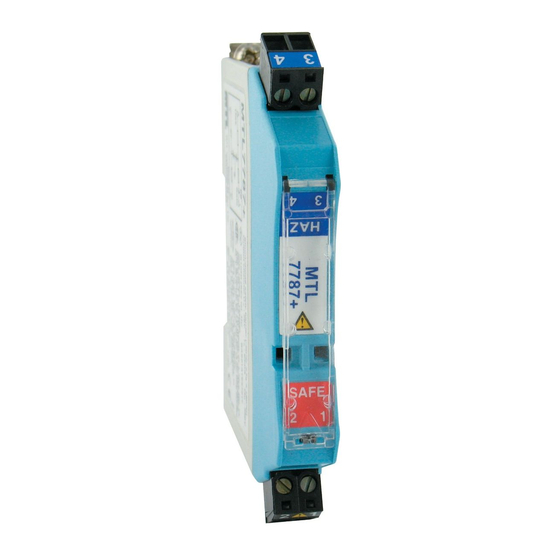
SERIES MTL7706/7787
ZENER BARRIER
Intrinsically Safe Barriers for Hazardous Locations
The SERIES MTL7706/7787 Zener Barrier is an intrinsically safe shunt-diode barrier
that can be used to communicate with and provide isolations for certain Dwyer
transmitters approved for use in hazardous areas. These barriers limit the amount of
energy allowed to pass into the hazardous area, which inhibit ignition in flammable
atmospheres.
FEATURES/BENEFITS
• Approved for use in hazardous areas
APPLICATIONS
• Electrically isolates pressure and level transmitters from unregulated circuits for
intrinsically safe applications
COMPATIBLE MODELS: 637, 608, SBLTX, PBLTX, IS626
Model
Approval
MTL7706
UL for class I; div. 1 groups A, B, C, D
CL II; div. 1 groups E, F, G; CL III div. 1
MTL7706
FM for class I, II, III; div. 1 groups B, C, D, E, F, G
MTL7706
FM for class I, II, III; div. 1 groups A, B, C, D, E, F, G
Note: Compatible models: 637, 608, SBLTX, PBLTX, IS626
MODEL CHART
FM
BASEEFA (ATEX)
Model
Group µF
mH Group µF
MTL7706
A & B
0.083
4.2
IIC
A & B
IIC
MTL7787
0.083
3.05
Region
(Authority)
Standard
Approved For
USA (FM) (UL)
3600,
AIS/I,II,III/1/Entity ABCDEFG-
3610 entity
SCI-942; NI/I/@/ABCD/T4
3611, 3810
[I/0] AEx[ia]IIC-SCI-942
UL698,
Entity; NI/1/2/IIC/T4;
UL913
Ta=140°F (60°C)
UL1604
Canada (CSA)
CAN/CSA
Class I, Div.2, Gps A, B, C, D;
E60070,
Ex nA [iA] IIC T4
IEC60079,
Class I, Xone 2, Aex nA IIC
C22.2
T4
UK (BASEEFA)
EN 50014,
EEx ia IIC
EN 50020
UK (BASEEFA)
EN 50039
EEx ia IIC
Systems
MTL7787
Dwyer
Series
IS626, SBLTX,
PBLTX
637
608
mH
0.083
4.2
0.083
3.05
Certificate/
File no.
3010737
1345550
BAS01ATEX7217
Ex01E2219
HAZARDOUS
AREA TERMINALS
SPECIFICATIONS
®
Transmitter Voltage: 16.2 V at 20 mA with 250 Ω load (negative w.r.t. earth); 11.0
V at 20 mA with 500 Ω load (negative w.r.t. earth).
Safe Area Output: 4 to 20 mA.
Load Resistance: 0 to 500 Ω.
Power Requirement: 20 to 35 VDC w.r.t. earth.
Accuracy: ±2 µA under all conditions.
LED Indicator: Green: Power indication.
Temperature Limits: Operating: -4 to 140°F (-20 to 60°C); Storage: -40 to 176°F
(-40 to 80°C).
Humidity: 5 to 95% RH.
Terminals: Accommodate up to 2.5 mm2 stranded or single-core.
Safety Description: 28 µV, 300 Ω, 93 mA.
Weight: 4.9 oz (140 g).
Agency Approvals: See table.
MODEL CHART
Model
Description
MTL7706
Zener barrier
Zener barrier
MTL7787
ACCESSORIES
Model Description
A-360 Aluminum DIN rail 1 m
DWYER INSTRUMENTS, INC. | www.dwyer-inst.com
SAFE AREA
TERMINAL
1/2
[12.70]
3-35/64
[90.09]
4-5/32
[105.57]
397
Advertisement
Table of Contents

Subscribe to Our Youtube Channel
Related Manuals for Dwyer Instruments MTL7706


Summary of Contents for Dwyer Instruments MTL7706
- Page 1 [90.09] 4-5/32 MTL7787 [105.57] The SERIES MTL7706/7787 Zener Barrier is an intrinsically safe shunt-diode barrier SPECIFICATIONS that can be used to communicate with and provide isolations for certain Dwyer ® Transmitter Voltage: 16.2 V at 20 mA with 250 Ω load (negative w.r.t. earth); 11.0 transmitters approved for use in hazardous areas.
- Page 2 MTL7700 Series Shunt-diode safety barriers Instruction Manual INM7700...
- Page 3 INM7700-6 Jan 2010...
-
Page 4: Table Of Contents
CONTENTS PAGE OVERVIEW ............. . 1 DESCRIPTION . - Page 5 INM7700-6 Jan 2010...
-
Page 6: Overview
MTL7700 Series INM7700-6 Jan 2010 Shunt-diode safety barriers Figure 1: MTL7700 Series shunt-diode safety barriers OVERVIEW DESCRIPTION This instruction manual contains all information needed to install, Introduction maintain, fault-find and test MTL7700 Series shunt-diode safety MTL7700 Series ‘fourth-generation’ intrinsically safe shunt-diode barriers. -
Page 7: Mtl7700 Series - Accessories
The tagging systems for individual modules and columns of barriers Type Application Key barriers are described here. They are shown below under Tagging accessories for columns of barriers. Analogue Resistance temperature detectors 7755ac Mounting accessories (figure 2) input Thermocouples, ac sensors 7756ac (low-level) 7760ac... -
Page 8: Safety Considerations
INSTALLATION General MTL7700 Series barriers clamp directly onto standard T-section DIN- rail (DIN EN 50 022). The simple mounting procedure for barriers is described in section 4.2 and for accessories in section 4.3. 4.1.1 DIN-rail length BEFORE mounting the barriers, make sure the rail length is sufficient for the proposed number of barriers and for other mounting ERB57O accessories. - Page 9 Item Refer to no. section: Action Hazardous- Safe-area area terminals terminals Before beginning installation, check that the safety documentation confirms that proposed system is fully certified (if applicable) and complies with the recommendations contained in the relevant sections of IEC 60079-14 for the gas group, temperature classification and area classification required.
- Page 10 TGL7700 TAG57 ERB57O IMB57 ETL7000 170mm ISP7000 Figure 5: Clearance for accessories Note: For high profile (15mm) DIN rail, add 7.5mm to vertical dimension 110mm 110mm 4.3.3 DIN-rail earth terminal (ETL7000) See figure 10. For those applications (the majority) in which the IS earth is NOT routed through the mounting surface, connections for routing the IS earth from the DIN-rail to an appropriate plant earth are made through earth terminals (ETL7000) clamped onto the DIN-...
- Page 11 Note: Early versions of TH7700 are hinged on two small locating M6 X 16 pins. Later versions are hinged by locating the clips at the hinged end into the rectangular appartures on the barrier body. The later design High - profile can be retrofitted on early modules by removing the hinge pins with DIN rail a knife.
-
Page 12: Wiring Connections
(BPL7700) can be used. Typical applications include hazardous-area switches, solenoids and 4–20mA transmitters; and the barriers it can be used with are the MTL7706, MTL7707+, MTL7787+, MTL7787P+ and MTL774x. See figure 14 for a typical power link installation applied to hazardous-area switches. - Page 13 (12AWG) must be connected PB7700 between ETM7 earth terminals located at each end of the rail and the ‘spare’ terminals on the ETL7000 terminals at each end of the column of barriers. See figure 17. MTL7706+ 1-5V MTL7787+ 5.3.4 Hazardous-area equipment isolation MTL7787P+ 250Ω...
-
Page 14: Connections To Dummy Barriers
TGL7700 TAG57 (optional earth rail) ERB57O ETM7 IMB57 Cable screens using earth rail ETL7000 Cable screens using module terminals ISP7000 Figure 17: Earthing and screening using module earth terminals or earth rail alternative 5.3.5 Bonding practice when hazardous-area f) In general, the use of barriers in all measurement leads reduces equipment cannot meet prescribed insulation the possibility of earth circulating currents causing measurement standards... -
Page 15: Fault-Finding
Hazardous area Safe area Hazardous area Zone 0, 1 or 2 (Zone 2) or safe area Enclosure DIN-rail Barriers Local distribution Safe-area transformer equipment Hazardous-area equipment incapable of withstanding insulation test 1Ω maximum Bonding conductor <100m: 4mm minimum 100 200m (maximum): 8mm minimum Figure 18: Bonding practice where hazardous-area equipment cannot meet required standards of insulation from earth Check that:... -
Page 16: Power Supply Check
Power supply check 8.1.1 Thermocouple circuit testing Thermocouple test and calibration equipment is rarely certified Check that the power supply to an individual barrier circuit (or to an intrinsically safe and therefore requires special authorisation before it MTL7798 power feed module or an MTL7799 dummy barrier can be used for testing or calibrating thermocouple circuits in sourcing the power bus ) is functional and that the voltage across the hazardous areas. -
Page 17: Tests For Active Barriers
30mA 0 - 30V 0 - 30V variable variable Figure 24: MTL7706+ test circuit 8.3.2 Tests for the MTL7707+ Since this unit incorporates a built-in protection circuit, it has to be Changeover tested in a different manner to an ordinary shunt-diode barrier. - Page 18 8.3.3 Tests for MTL774x Bussed Power V s + The MTL774x range are switch/prox input barriers with a choice of changeover relay contacts or a solid state switch acting as the safe area interface. Relay contacts provide a universal interface capable of switching a wide range of signals including ac, low level and high Channel 1 Channel 1...
-
Page 19: Test Tables For Passive Barriers
Test tables for passive barriers Tables 4 to 10 detail the tests for all MTL7700 Series ‘passive’ barriers. In the ‘diode test’ columns, the figures adjacent to the diode description indicate the number of forward-biased diodes used in the barrier chain. Using the multimeter diode test function and knowing the diode voltage drop figures (approximately 0.6V for each Zener diode and 0.3V for each Schottky diode), the expected reading across the diode chain can be determined. - Page 20 BARRIER DATA MULTIMETER TESTS CONSTANT-CURRENT TESTS Safety End-to-end Diode Diode Terminal Terminal model Description Resistance Test Test Voltage Voltage Ω Ω @ 10μ μ A @ 20mA Ω Ω Min Max ∞ ∞ 7728ac 28 300 93 26.7 25.6 27.2 Table 6: Single channel BARRIER DATA MULTIMETER TESTS...
- Page 21 BARRIER DATA MULTIMETER TESTS CONSTANT-CURRENT TESTS Safety End-to-end Diode Diode Terminal Terminal model Description Resistance Test Test Voltage Voltage Ω Ω @ 10μ μ A @ 20mA Ω Ω Min Max ∞ 7787+ 28 300 93 26.6 27.4 26.7 27.6 ∞...
-
Page 22: Appendix A: Typical Wiring Connections For Specific Applications
Power Bus Hazardous Safe Area Area Power +26.6V Logic signal Power +26.6V Power Bus MTL7789+ Logic signal Power +26V Signal MTL7706+ MTL7787+ 1-5V MTL7787P+ Figure A5: 2-channel switch inputs 4 -20mA 250W MTL7788+ Hazardous Safe Area Area Figure A1: 2-wire transmitters... - Page 23 Hazardous Safe Hazardous Safe Area Area Area Area +26V MTL7728+ MTL7761ac --7V Figure A9: Analogue output Sense MTL7764ac — Hazardous Safe Area Area Power Bus 620Ω +22.9 - 30V Output (mV) 10kΩ MTL7761ac MTL7745 CH 1 Figure A10: Single channel switch/proximity input with Line Figure A13: Strain-gauge bridges Fault Detect Hazardous...
- Page 25 MTL Instruments Pty Limited MTL Italia srl 9 /12 Billabong Street Via Cantù 11 Stafford I - 20092 Cinisello Balsamo MI Queensland 4053 Italy Australia Tel: +39 (0)2 61802011 Fax: +39 (0)2 61294560 Tel: + 61 1300 308 374 Fax: + 61 1300 308 463 E-mail: info@mtl-inst.it E-mail: enquiries@mtlaus.com.au MTL Instruments KK...
Need help?
Do you have a question about the MTL7706 and is the answer not in the manual?
Questions and answers