Table of Contents
Advertisement
Quick Links
Advertisement
Table of Contents

Related Manuals for Chziri ZJR1 Series


Summary of Contents for Chziri ZJR1 Series
- Page 1 SOFTSTART USER'S MANUAL ZJR1 SERIES...
-
Page 2: Table Of Contents
Foreword Chapter 1 Introduction to the Product..........1 1.1 Safety Instructions............1 Thank you for your purchase of ZJR1 series of motor soft starter produced by 1.2 Product Inspection upon Arrival........2 Ziri Electrical Technology Co.,Ltd. (hereinafter referred to as ZIRI Company). 1.3 Demonstration of the Specifications Label and Model...2 This manual introduces the installation, operation, function setting, trouble 1.4 Outline of the Product.......... -
Page 3: Chapter 1 Introduction To The Product
Chapter 1 Introduction to Product 1.2 Inspection upon Arrival Chapter 1 Introduction to Product This product is guaranteed a high level of quality with strict outgoing inspection, crushproof and shockproof packaging. But there is the possibility of damage in transit by carelessness. So it is necessary to unpack the package upon receipt of the product and perform the following steps: The installation and wiring of motor soft starter should be... -
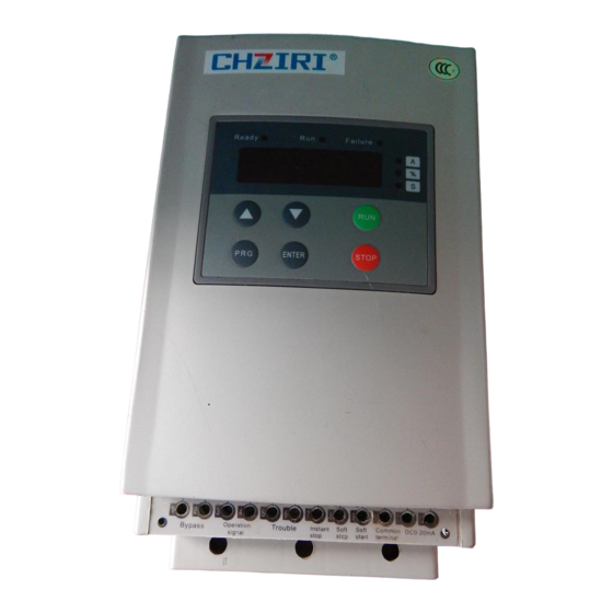
Page 4: Outline Of The Product
Chapter 1 Introduction to Product Chapter 1 Introduction to Product 1.4 Outline of the Product 1.5 Models and Specifications Schedule of Models & Specifications Input Terminals of Power Connect to the bypass contactor Supply (R, S, T) (L21, L22, L23) Max Adaptive Input Voltage Rated Current... -
Page 5: Technical Indications
Chapter 1 Introduction to Product 1.6 Technical Indications Chapter 2 Installation and Wiring Item Item Description 2.1 Operating Conditions Input Input Voltage Three-phase 380V-15% 415+10% Power Use the motor soft starter in the following environmental conditions: Frequency Supply 50/60Hz Altitude: Maximum 1000m above sea level. Derating should be performed Squirrel-cage three-phase asynchronous motor Adaptive Motor before use if the altitude is higher than 1,000M. -
Page 6: Wiring
Chapter 2 Installation and Wiring Chapter 2 Installation and Wiring 2.3.2 Description of Main Circuit Terminals 2.3 Wiring Functional Description Terminal Mark Terminal Name The wiring of motor soft starter should be operated only by professionals experienced in high and low voltage electric circuit and should read this Connect to three-phase input power Main Circuit Input Terminal supply. -
Page 7: Chapter 4 Operation
Chapter 2 Installation and Wiring Chapter 2 Installation and Wiring The length of the wire shall be as short as possible (not exceed 30m generally) 2.3.3 Main Circuit Connection Diagram because the control circuit is easily influenced by external interference. Power Supply The recommended wire size of the control circuit connecting wire is 0.75mm . - Page 8 Chapter 2 Installation and Wiring Chapter 2 Installation and Wiring 2.3.6 Relay & Non-local Control Wiring Diagram 2.3.5 External Control Wiring Modes Thee-phase Control Mode Relay Control Mode Instantaneous Stop Instantaneous Stop Stop Stop Start Start Common Port Common Port Control Terminal Lead Relay Control Mode Two-wire Control Mode...
- Page 9 Chapter 2 Installation and Wiring 2.4 Selection List of Peripheral Appliances Chapter 3 Operation Panel Option list of the motor soft starter peripheral breakers, electromagnetic contactors and cables, shown as below: Cable 3.1 Description of Operation Panel Electromagnetic Breaker Motor Rated Motor contactor Sizes...
- Page 10 Chapter 3 Operation Panel Chapter 3 Operation Panel 3.2 Panel Operation 3.3 Description of Panel Display Parameter Modification Example Eg. If the control mode is changed to external terminal control, just set the code P9 to 02. Codes Description Displayed Action Display Description...
-
Page 11: Operation
Chapter 4 Operation Chapter 5 Description of Function Parameters 4.1 Check before operation. 5.1 Schedule of Function Parameters The following steps should be inspected and confirmed before the soft starter is put into operation: Function Default Setting Range Function Name MEMO Be sure that the application ambient and the input power supply complywith the Code... -
Page 12: Detailed Description Of Function Parameters
Chapter 5 Description of Function Parameters Chapter 5 Description of Function Parameters 2 Free Stop 5.2 Detailed Description of Function Parameters If the code P2 is set to "0", then free stop mode is selected. In this stop mode, once stop command is received, the soft starter will disconnect the Functional Code P0 Inception Voltage Setting Range: 30~70% Factory Default Setting: 30% bypass contactor and disable voltage output of the thyristor. - Page 13 Chapter 5 Description of Function Parameters Chapter 5 Description of Function Parameters will not go up any more. Then, with gradual raise of output value, the motor will 3) Kick Start accelerate gradually. When the motor speed reaches the rated speed of rotation, the When the code P7 is set to "2"...
- Page 14 Chapter 5 Description of Function Parameters Chapter 5 Description of Function Parameters 5) Voltage and Current-limiting Double-closed Loop Start When the code P7 is set to "5" (double closed-loop), then this start mode is Functional Code PA Parameter Protection Setting Range: 00~01 Factory Default Setting: 01 selected.
- Page 15 Chapter 5 Description of Function Parameters Chapter 5 Description of Function Parameters Functional Code PC Motor Rated Current Setting Range: 11~1200 2) Protective Trip Curve Factory Default Setting: Set according to the specifications Function Description: This parameter should be set in conformity with rated current value displayed on specifications label of the motor.
-
Page 16: Chapter 6 Trouble Protection & Treatment
Chapter 6 Trouble Protection & Treatment Chapter 6 Trouble Protection & Treatment 6.1 Schedule of Protection Operating 6.2 Trouble Diagnosis and Troubleshooting Protective functions enabled with an immediate tripping once anomaly of the soft starter occurs. Refer to the descriptions below for warnings and relevant contents displayed on LED. -
Page 17: Chapter 7 Structure And Sizes
Chapter 7 Structure and Sizes Chapter 7 Structure and Sizes 7.1 Outline Sizes & Install Sizes Install a screw Outline Sizes Install Sizes Rated Rated Models Weight Power(KW) Current(A) (Kg) Rated Rated Outline Sizes Install Sizes Models Weight Power(KW) Current(A) (Kg) Made to Order Notes:... -
Page 18: Chapter 8 Quality Warranty
Chapter 8 Quality Warranty Appendix 1 Varieties of Application Loads 1) Warranty Period Under Normal Conditions This soft start can meet the requirements of most heavy loads. The table below is for reference only. We provide guarantees for repair, replacement and return of the Current- Voltage Start purchase in 1 month from the date of use.
Need help?
Do you have a question about the ZJR1 Series and is the answer not in the manual?
Questions and answers