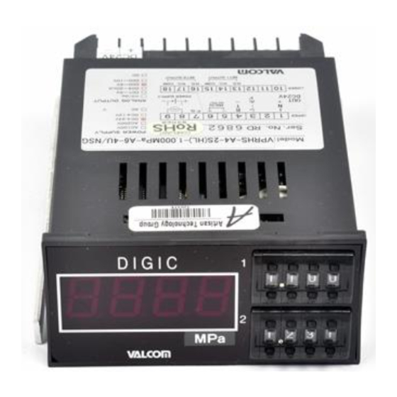
Summary of Contents for Valcom VPRHS-U
- Page 1 sales@artisantg.com artisantg.com (217) 352-9330 | Visit our website - Click HERE...
- Page 2 VPRHS-U TYPE VPRVS-U TYPE Operation Manual 1. General Specifications 2. Placement of Internal Adjusting Controls and Operation Keys 3. Terminal Connections 4. Particularly Important Precautions 5. Zero-shifting Function 6. Optional Peak-holding Function 7. Optional Auto-zeroing Function 8. Maintenance, Inspection, and Adjustment 9.
-
Page 3: For Safe Use
For safe use Thoroughly read the precautions described below for correct use. Improper use will cause failures or accidents such as fire and shock hazards. To avoid such accidents, be sure to observe the precautions. Save this manual in an appropriate place for future reference even after you read it. "WARNING"... - Page 4 Neglecting this may cause shock hazards or failures. When one of abnormal conditions shown below is detected, turn OFF the power, and notify your local dealer or VALCOM of it, or return the amplifier for repair. ○Smoking occurs.
-
Page 5: General Specifications
1. General Specifications No.Q-0600-0057-05 -4-... -
Page 6: Terminal Connections
Placement of Internal Adjusting Controls and Operation Keys “VPRVS” Series “VPRHS” Series 3. Terminal Connections Upper terminals Lower terminals For relay output (Types: 1S, 2S) Lower Upper terminals terminals For open-collector output (Types: 1SO, 2SO) Lower terminals Sensor connection A (+EXCITATION) Peak-holding terminal (activated when short-circuited together with the terminal No. - Page 7 Caution: The sensor power supply (EXCITATION) is the power supply for a sensor with VALCOM built-in amplifier. (If the power supply specification for the model (*2) specifies an AC power supply, the standard specification is 12 VDC, 25 mA.) (If the power supply specification for the model (*2) specifies a 24VDC power supply, the standard specification is 15 VDC, 40 mA.) .
- Page 8 * When you must perform calibration, follow the procedure described in "8. Maintenance, Inspection and Adjustment." (*While performing calibration, do not touch any control which does not need adjustment.) * When a measurable limit (FS.±approx. 2%) is exceeded, the display starts flashing. (The reading remains unchanged.) When zero-shifting has been performed, the zero-shifting amount is added to or subtracted from the original measurable limits.
- Page 9 6. Optional Peak-holding Function * Short-circuiting the terminal No. 10 (P) and the terminal No. 12 (COM.) activates the peak-holding function. * When the terminals are opened, the unit returns to normal measurement operation. * P (Peak holding) Actual input Peak holding Reading Peak command...
- Page 10 Normally, this unit requires only zero adjustment for maintaining high accuracy. When this unit needs recalibration, send it to VALCOM or perform calibration by following the procedure below. 1) Prepare a calibrator with guaranteed accuracy. 2) If the input must correspond to the "0" indication, make sure that the indicated value is "0".
- Page 11 9. I/O Schematics Analog input schematic (A2, A3, A4, and A5) Control input schematic (P and Z) To internal CPU board 0.1uF Control input Analog output schematic (A1, A2, A4, and A5) Internal D/A output Output (+) 100-1/4W 0.1uF Output (-) No.Q-0600-0057-05 -10-...
-
Page 12: Dimensional Drawing
10. Dimensional drawing Unit: mm “VPRHS” Series 17.5 41.5 “VPRVS” Series DIGIC S ET1 9 9 9 S ET2 9 9 9 1 10 17.5 41.5 No.Q-0600-0057-05 -11-...


Need help?
Do you have a question about the VPRHS-U and is the answer not in the manual?
Questions and answers