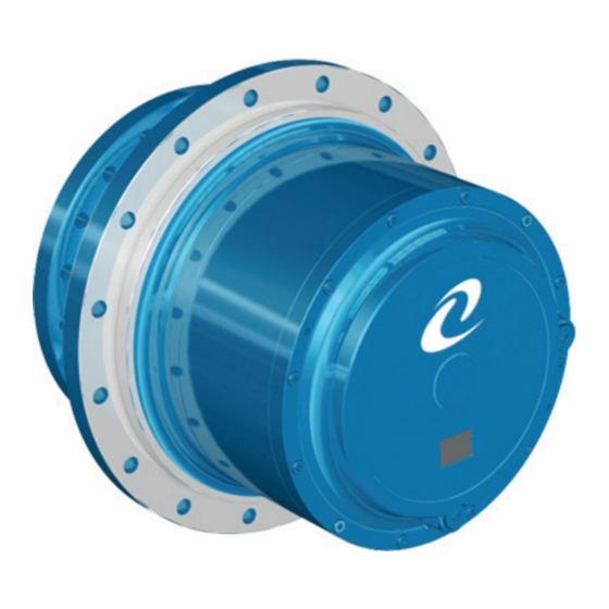
Summary of Contents for Comer PGRF Series
- Page 1 Certified Quality System UNI EN ISO 9001 : 2008 SERVICE MANUAL PGRF PGRF series Release A10/14...
-
Page 2: Table Of Contents
First issue 10/14 Release A10/14 INDEX GENERAL INFORMATION ....................................... 3 GEARBOX UNIT IDENTIFICATION ................................3 RISKS AND PRECAUTIONS ..................................3 TRANSFER AND STORAGE ..................................3 HANDLING ........................................3 PRODUCT DISPOSAL ....................................3 GEARBOX UNIT ......................................4 INTENDED USE AND LIMITATIONS................................4 LUBRICANT ......................................... -
Page 3: General Information
First issue 10/14 Release A10/14 GENERAL INFORMATION GEARBOX UNIT All the data which characterize the gear unit are reported on the name plate attacched on the unit. IDENTIFICATION Safety of authorized workers must be guarantee. RISKS AND Provide all authorized worker with all necessary and specific IPG. PRECAUTIONS Example: Slip-proof shoes should be worn, because there is oil in the reduction gear and during maintenance some of it may leak in the working area. -
Page 4: Gearbox Unit
First issue 10/14 Release A10/14 GENERAL INFORMATION GEARBOX UNIT Most materials of these gearboxes are made of high quality steel and cast iron that have to comply with the increasingly strict requirements on workability, resistance to distortion, to fatigue failures and to wear, safety and durability. All technical information are described in the documents referred to the specific unit code. -
Page 5: Ordinary Maintenance
First issue 10/14 Release A10/14 ORDINARY MAINTENANCE Maintenance operations must be carried out by qualified, trained and authorised personnel MAINTENANCE To guarantee long life and excellent performance to the gear unit, maintenance opera- tions must be done on a regular basis. Before maintenance operations, authorized people must disconnect the unit power supply, putting it “out of order”, taking all the necessary precautions to ensure it cannot be restar- ted accidentally or any of its moving parts. -
Page 6: Oil Replacement Procedure
First issue 10/14 Release A10/14 OIL REPLACEMENT PROCEDURE Maintenance operations must be carried out by qualified, trained and authorised personnel PROCEDURE: DRAINING • Position the unit with drain plug ( ) placed down. • Drain the oil: unscrew the drain plug ( ) and, to ensure that all the oil has been removed, also unscrew the level plugs. -
Page 7: Installation And Start Up
First issue 10/14 Release A10/14 INSTALLATION and START UP Installation and start-up must be carried out by qualified, trained and authorised personnel Before installation check and verify: PRELIMINARY • motor type and connection; CHECKS AND • that unit components are not damaged and that the centering parts are not rusty; INSTALLATION • unit installation diagram;... -
Page 8: Troubleshooting
TROUBLESHOOTING Problems Possible cause Remedies 1) Damaged or worn seals; 1) Contact Comer Industries; Oil leaks 2) Breather plug clogged; 2) Clean or substitute the plug 1) There is no oil in the unit; 1) Filling the unit with oil;... -
Page 9: Torque Wrench Setting
First issue 10/14 Release A10/14 TORQUE WRENCH SETTING (N x m) Screw on steel or cast iron PGRF...

Need help?
Do you have a question about the PGRF Series and is the answer not in the manual?
Questions and answers