
Related Manuals for Keithley 7709


Summary of Contents for Keithley 7709
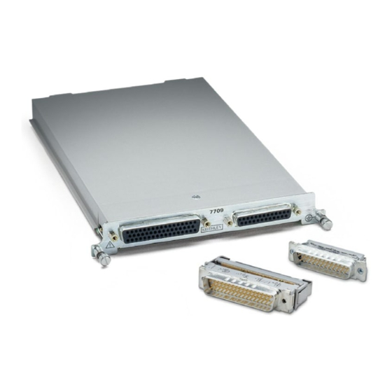
- Page 1 Model 7709 User’s Guide PA-771 Rev. B / 8-03 A G R E A T E R M E A S U R E O F C O N F I D E N C E...
-
Page 2: Safety Precautions
Keithley products are designed for use with electrical signals that The instrument and accessories must be used in accordance with its are rated Measurement Category I and Measurement Category II, as specifications and operating instructions or the safety of the equip-... - Page 3 Keithley Instru- symbol on an instrument indicates that the user should re- ments. Standard fuses, with applicable national safety approvals, fer to the operating instructions located in the manual.
- Page 4 Model 7709 Keithley Instruments, Inc. 28775 Aurora Road User’s Guide Cleveland, Ohio 44139 (440) 248-0400 Fax: (440) 248-6168 www.keithley.com The information in this section is organized as follows: • Card configuration – schematic on page • Rows 1 and 2 on page •...
-
Page 5: Card Configuration - Schematic
Although the Model 7709 relays are the latching type (relays hold their state even after power has been removed), all relay states are set to open a few seconds after either a power cycle or an *RST command is issued. - Page 6 Figure 1 Simplified schematic for Model 7709 Columns HI LO HI LO HI LO HI LO HI LO HI LO HI LO HI LO Input To DMM Backplane Sense Matrix Column 3 Crosspoint HI LO (1 of 48) Ch 43...
- Page 7 Rows 1 and 2 System channel operation ( ROUT:CLOS command) is used to close Rows 1 and 2 channels to connect a DUT to the DMM. With a 2-wire function selected (i.e., DCV), system channels 1 through 8 can be closed. When one of these channels is closed, channel 50 automatically closes to connect Row 1 to the DMM Input.
- Page 8 Rows 3 through 6 As shown in Figure 1, channels 17 through 48 are the channels for Rows 3 through 6. These channels can only be closed using multiple channel operation ( ROUT:MULT:CLOS command). For system channel operation, these channels are invalid (cannot be closed).
-
Page 9: Matrix Expansion
Basic matrix column expansion The number of columns in a matrix test system can be increased by simply installing another Model 7709 in the mainframe. For the Model 2700/2701 mainframe, adding a second Model 7709 increases the total number of columns to 16. For the Model 2750, five installed Model 7709s provide 40 columns for DUT. - Page 10 Two matrix module test system using an external source Input External Source 7709 7709 Multiple channel 25 of module #1 closed to power DUT 1. System channel 1 of module #2 closed to connect DUT 1 to DMM Input. Note: Each signal path shown in this illustration is actually a two conductor...
- Page 11 NOTE Techniques to daisy-chain rows are explained in “Connections and wiring.” Figure 7 Daisy-chained matrix modules 6 × 16 Matrix: 7709 7709 (16) External Source Multiple channel 30 of module #2 closed to connect external source to column 6 of module #2.
-
Page 12: Connections And Wiring
• Before making or breaking connections, make sure power is removed from all external circuitry. • Do not connect signals that may exceed the maximum specifications of the Model 7709 or external wiring. Specifications for the Model 7709 are provided at the end of this section. - Page 13 Figure 8 shows the pin numbers for the Model 7709 rear panel connectors. The 50-pin D-shell is used for DUT and external source connections. The 25-pin D-shell is used to daisy-chain the matrix rows of two or more Model 7709s. Terminal identification for the female connector pins are contained in...
- Page 14 Any unused D-shell connector must have the connector cover installed. The Model 7709 is supplied with one 50-pin male IDC ribbon cable connector, and one 25-pin male IDC ribbon cable connector. These ribbon cable connectors mate to the D-shell connectors of the switching module.
- Page 15 The connector of the prepared ribbon cable assembly mates to the 50-pin D-shell connector of the Model 7790 as shown in Figure 10. Make sure the connector cover for the 25-pin D-shell connector is installed if it is not going to be used. Table 2 Terminal identification for 50-conductor IDC ribbon cable and 7709 DB-50 connector Ribbon Cable*: Matrix DB-50...
- Page 16 Figure 9 Ribbon cable terminal identification 50-Pin D-Shell IDC Ribbon Cable — 50-Conductor Male IDC 1 Brown Row 1 2 Red 3 Orange Row 2 4 Yellow 5 Green Row 3 6 Blue 7 Violet 8 Grey 9 White Row 4 10 Black 11 Brown Row 5...
- Page 17 1000V. The connector cover for the 25-pin D-shell connector on the Model 7709 must be installed if it is not going to be used. If the connector is left open, an electrical shock hazard may be present.
- Page 18 Row daisy-chain connections Row daisy-chain ribbon cable assembly WARNING When using IDC ribbon cable, DO NOT exceed 42V anywhere in the test system or to the front panel inputs of the Model 27xx. A convenient method to daisy-chain the rows of two or more Model 7709s, is to use a 25-conductor ribbon cable assembly with IDC ribbon cable connectors attached to it.
- Page 19 4. Route the cable over the back side of the connector and install the strain relief for the connector. Make sure the cable is firmly clamped to the connector body. Figure 13 shows how the cable is routed through the strain reliefs of the connectors. 5.
- Page 20 Columns 1-8 7709 7709 Columns 33-40 Columns 9-16 Slot 2 Slot 5 Row Daisy-Chain Cable Table 3 Terminal identification for 25-conductor IDC ribbon cable and 7709 DB-25 connector Ribbon Cable*: Matrix DB-25 Ribbon Cable*: Matrix DB-25 Conductor Color Terminal Pin #...
- Page 21 All solder cup wiring must be rated for the maximum voltage in the system. For example, if 1000V is applied to the front terminals of the DMM, all matrix module wiring must be rated for 1000V. Figure 15 Row daisy-chaining using solder cup connectors 7709 7709 (Slot 2) (Slot 1) DB-50 DB-25...
- Page 22 Figure 16 Ω2-Wire and thermistor connections Column 1 Resistors or (Columns 2–7) Thermistors Column 8 Figure 17 Ω4-Wire and RTD connections Resistor or Column 1 4-Wire RTD (Columns 2, 3) Resistor or Column 4 4-Wire RTD Column 5 (Columns 6, 7) Column 8...
- Page 23 Figure 18 Voltage connections (DC or AC) DC Voltage AC Voltage Column 1 (Columns 2–7) Column 8...
-
Page 24: Connection Log
Connection log Make a copy of Table 4 and affix it to the cover of Model 7709. Use this to record connection information and channel descrip- tions as needed. Table 4 Connection log Model 7709 Column/Row Color Description Col 1... -
Page 25: Channel Assignments
Operation Detailed information to close and open switching module channels are provided in Section 2 of the Model 27xx User’s Manual. The following summarizes basic operation, and provides operating information specific to the Model 7709. Channel assignments The Model 2700/2701 has two slots for switching modules and the Model 2750 has five slots. To control the appropriate matrix module, the slot number must be included with the matrix module channel number when you specify a channel. - Page 26 Making amps measurements – In order to perform amps measurements, you must use the front panel inputs of the 27xx mainframe. You can still use the 7709 module for other aspects of the test (such as controlling a bias supply for DUT), but you must use multiple channel operation to close channels.
-
Page 27: Multiple Channel Operation
For the Model 7709, multiple channel operation provides independent control of channels 17 through 48 (Rows 3 through 6). When you close multiple channel, only the specified channel (or channels) will close. Other closed channels are not affected. - Page 28 Ordering information To place an order, or to obtain information concerning replacement parts, contact your Keithley representative or the factory (see back cover for addresses). When ordering parts, be sure to include the following information: • Card model number (Model 7709).
- Page 29 Table 5 Model 7709 parts list Circuit Designation Description Keithley Part No. C1, C4, C11, C12, C14, C15, C18 CAP, .1UF, 20%, 50V, CERAMIC (1206) C-418-.1 CAP, 220UF, 20%, 10V, TANTALUM C-558-220 C2, C19, C20 CAP, 4.7UF, 10%, 35V, TANTALUM C-476-4.7...
- Page 30 Figure 19 Model 7709 component layout (Side - 06) MC - 612 CR65 CR64 CR66 CR45 Primary Side Components (Side - 06) For component information, see product structure.
- Page 31 Figure 20 Model 7709 component layout (Side - 01) Secondary Side Components (Side - 01) For component information, see product structure.
- Page 32 7709 6×8 Matrix Module GENERAL Columns MATRIX CONFIGURATION: 6 rows × 8 columns. CONTACT CONFIGURATION: 2 pole Form A. FIRMWARE: Specified for Model 2700 rev. B03 and Model 2750 rev. A01. Input To DMM RELAY TYPE: Latching electromechanical. Backplane ACTUATION TIME: <3ms.
- Page 33 Specifications are subject to change without notice. All Keithley trademarks and trade names are the property of Keithley Instruments, Inc. All other trademarks and trade names are the property of their respective companies. Keithley Instruments, Inc. 28775 Aurora Road • Cleveland, Ohio 44139 • 440-248-0400 • Fax: 440-248-6168 1-888-KEITHLEY (534-8453) •...
Need help?
Do you have a question about the 7709 and is the answer not in the manual?
Questions and answers