
Summary of Contents for Hurricane SCH25
- Page 1 from Calcutt Boats Service and Troubleshooting Manual Diesel Hot Water Heating System for Boats and Recreational Vehicles Version 1.0...
- Page 2 Copyright © October 2013 MANUFACTURED BY: SOLE EUROPEAN DISTRIBUTORS: International Thermal Research Calcutt Boats Ltd. 2431 Simpson Road, Tomlow Road, Stockton, Richmond, BC, Canada, V6X 2R2 Southam, CV47 8HX, UK Tel: +1 604-278-1272 Tel: +44 1926 813757 Fax: +1 604-278-1274 Fax: +44 1926 814091 Email: itr@shaw.ca Email: info@dieselheating.com...
-
Page 3: Table Of Contents
Table of Contents General Information ................ 1 TOOLS ..................1 MAXIMUM TORQUE VALUES ............1 Operation of the Hurricane SCH25 ..........3 1.1. Component Views..............4 1.2. Burner ................6 Control Board ................9 Troubleshooting ...............13 3.1. Overview ................13 3.2. - Page 4 5.3.2. Igniter ................34 5.3.3. Fuel Nozzle..............35 5.3.4. Flame Sensor...............36 Appendices..................37 Appendix 1 - Technical Bulletins ............37...
-
Page 5: General Information
General Information TOOLS The tools in this list should be considered the minimum required for performance of routine maintenance, servicing and minor repair work. • Spanner sizes 11/32, 9/16, 5/8, 7/8, 15/16, 1 3/8 • Socket sizes ¼, 5/16, 7/16, 11/32 •... - Page 6 Page 2...
-
Page 7: Operation Of The Hurricane Sch25
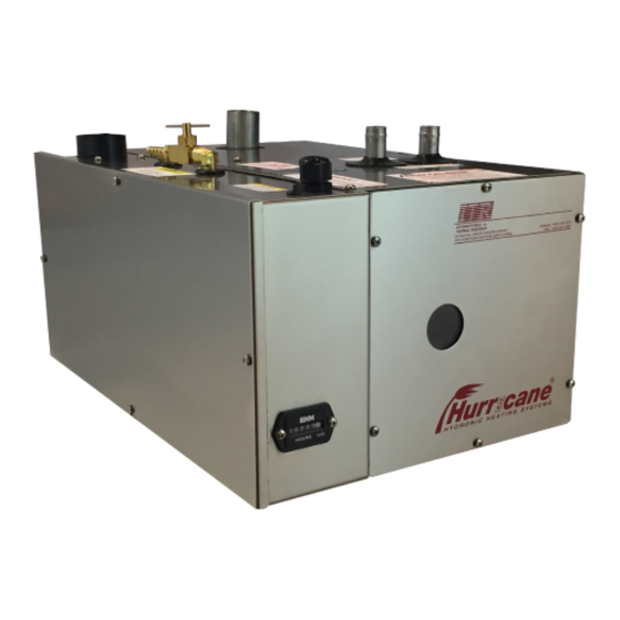
1. Operation of the Hurricane SCH25 The Hurricane SCH25 has a single source of heat; a 25,000 BTU burner. EXHAUST AIR INTAKE HOT WATER COLD WATER FUEL INLET FUEL RETURN FLAME OBSERVATION WINDOW HOURMETER CABLE TO CONTROL BOX NEGATIVE TO... -
Page 8: Component Views
1.1. Component Views FUEL BLEED/RETURN VALVE COMPRESSOR COMBUSTION FAN FUEL REGULATOR FUEL PUMP HOURMETER THERMAL CUTOFF FUEL BLOCK IGNITER FUEL SOLENOID FLAME SENSOR HOURMETER BURNER & COUNTERFLOW TUBE Page 4... - Page 9 COMBUSTION CHAMBER NOZZLE BURNER & COUNTERFLOW TUBE Page 5...
-
Page 10: Burner
1.2. Burner The burner consists of the following components: Fuel inlet Fuel Pump Fuel return/bleed Fuel filter Fuel regulator Fuel solenoid Flame sensor Nozzle block Nozzle 10. Igniter 11. Combustion fan 12. Thermal cutoff 13. Compressor 14. Air filter Figure 1: Burner schematic When the heater is turned on (service switch on and remote switch on) and there is a call for heat from either the room thermostat and/or the cylinder thermostat, it will go through the following ignition sequence:... - Page 11 1. The combustion fan will turn ON and run for 20 seconds. 2. The igniter will turn ON and the combustion fan will turn OFF. 3. The igniter will glow for 10 seconds to allow it to reach ignition temperature. 4.
- Page 12 combustion fan has faulted. In this case all of the burner components will shut down immediately. Page 8...
-
Page 13: Control Board
2. Control Board • Control box and board – The main control board is contained in a stainless steel control box and is connected to the heater via a 15ft/4.6m long, ½in/13mm diameter interface cable. All components in the heater unit are pre-wired to the main terminal block on the control board - Figure 3 shows the connections. - Page 14 • Battery connector – Connection points for the positive and negative power from the house battery to the heater. • Remote connector – Connection point for the cable from the remote LCD panel. • Service switch – The service switch allows full (service switch on) or partial (service switch off) operation of the functions of the heater control board.
- Page 15 BYPASS T8 T9 T10 T11 T12 T13 T14 T1 T2 T3 T4 T5 T6 T7 RESET PUMP BURNER SENS- SENS+ S_OUT TEMP FUEL COMP T1 W1 W2 A1 S/W P+ F2 T3 PUMP JUMPER IN "OFF" POSITION PUMP Figure 2: Control Board Page 11...
- Page 16 Figure 3: Wiring Diagram Page 12...
-
Page 17: Troubleshooting
Should a problem exist, the board will shut down. ® You can easily monitor your HURRICANE SCH25 heater’s operation by checking the electronic control box. -
Page 18: Heater Cycling (Normal Operation)
• The diagnostic code will be displayed. • The control board will purge the system with the combustion fan and circulating pump for two minutes. • If the remote switch is put in the ON position, the control board will resume operation and a small red LED will glow near the lower right hand corner of the digit. -
Page 19: Voltage Low Or High
• If the heater fails to resume operations, check the thermostat and their connections. 3.8. - Voltage Low or High The battery or power supply voltage is below 11Vdc or above 15Vdc • The burner will shut down. • The diagnostic code, will be displayed. -
Page 20: Fuse Blown
the battery. The ground wire should be a minimum 10 gauge and connected directly to the battery. 3.10. - Fuse Blown One of the fuses on the control board has blown. • The burner will shut down. • The diagnostic code, will be displayed. -
Page 21: Combustion Fan
• The buzzer will sound for 10 seconds. • The control board will purge the system with the combustion fan and circulating pump for two minutes. • In order to restart the burner, check the ignitor and connections. Then reset the fault by switching the service switch or the remote panel switch OFF then ON again if the ignitor is open or by the service switch only if the ignitor is shorted. -
Page 22: Flame Out
3.15. - Flame Out The flame went out or did not ignite. • The burner will shut down. • The diagnostic code, will be displayed. • The control board will try to restart the burner two more times. After two unsuccessful restart attempts, the buzzer will sound for 10 seconds. -
Page 23: Compressor
• If the conditions that caused the flame fault have been addressed and the heater still does not ignite, the thermal cutoff may have been activated by an overheat condition within the burner box. Using a multimeter, check for continuity across the leads of the thermal cutoff. -
Page 24: Water Pump On (Green)
mode will timeout in five minutes. After the first three minutes running, it will automatically purge for the last two minutes. 3.18. Water Pump On (Green) The green light located directly under the LED digit on the main board will come on whenever the circulating water pump is energized. 3.19. -
Page 25: Lcd Readout Remote Panel
Test Point Component Results / Optimal Condition Overheat The voltage will be 0 volts if an overheat Aquastat condition is occurring or has occurred in the past two minutes (overheat aquastat is open). voltage will be between 4.8 and 5 volts if the overheat aquastat is closed. -
Page 26: Reduced Output
flashing and the board still shuts down, diagnostic code Flame Out, the board may be defective. 3.22. Reduced Output The heater may run without faulting, but at a reduced output. If this is noticed, it could be caused by the following: •... -
Page 27: Step-By-Step Troubleshooting
4. Step-by-step Troubleshooting 4.1. Flame Out Check the following before continuing with the troubleshooting: • The fuel supply from the diesel tank to the fuel inlet of the heater must be from a dedicated fuel pickup on the top of the tank. •... - Page 28 Q2: When the fuel pump is running, does fuel come out of the bleed valve? IF YES: Place your finger on the air compressor’s air filter. Once the air compressor turns on, there should be enough suction to keep your finger in place. Proceed to Q3. IF NO: 1.
- Page 29 2. Once the fuel pump has been replaced, attempt to restart the heater. When the fuel pump starts running, ensure that fuel flows from the open fuel return bleed valve. Proceed to Q5. Q5: Once the fuel pump has been replaced, attempt to restart the heater.
- Page 30 Turn on the service switch and attempt to run the heater. Proceed to Q8. Q8: Does the heater fire once the plunger from the fuel solenoid is removed? IF YES: Problem solved. Replace the fuel solenoid. To replace the fuel solenoid, refer to 5.3.1. IF NO: Contact Calcutt Boats for further assistance.
- Page 31 2. Clean the flame sensor hole using high pressure air. 3. Screw the flame sensor (clockwise) into the fuel block. 4. Connect the flame sensor wires to the connectors with matching YELLOW heat-shrink. 5. Screw the front cover back in place. 6.
- Page 32 inlet of the fuel solenoid could have been damaged. To check this fuel line for leaks, do the following: Turn off the service switch and allow the heater to completely power down (this will take 2 minutes). 1. IMPORTANT: Disconnect the main power (12VDC) from the heater.
-
Page 33: Voltage
IF NO: Refer to the previous section (intermittent sputtering). If this section does not solve the problem, contact Calcutt Boats for further assistance. 4.2. Voltage Check the DC voltage to the heater using a multi-meter. Note that the voltage at the battery is not necessarily the voltage supplied to the heater. - Page 34 Page 30...
-
Page 35: Servicing The Hurricane Sch25
5. Servicing the Hurricane SCH25 5.1. Indications Service Is Required The flame is a dirty orange colour. Start the heater and place your finger on the air compressor’s air filter. Once the air compressor turns on, there should be enough suction to keep your finger in place. -
Page 36: Cleaning The Combustion Chamber
IF NO: Contact Calcutt Boats for further assistance. 1000 hours has passed since the last service. The following service needs to be done after 1000 hours of operation: • Replace the internal fuel filter. • Clean or replace the fuel nozzle; refer to 5.3.3. •... -
Page 37: Parts Replacements
5.3. Parts Replacements 5.3.1. Fuel Solenoid To install the fuel solenoid, do the following: 1. Turn off service switch and allow the heater to completely power down (this will take 2 minutes). 2. IMPORTANT: Disconnect the main power (12VDC) from the heater. Disconnecting the 12VDC power ensures that the heater will not attempt to fire if the service switch is accidentally turned ON. -
Page 38: Igniter
5.3.2. Igniter To install the igniter, do the following: 1. Turn off service switch and allow the heater to completely power down (this will take 2 minutes). 2. IMPORTANT: Disconnect the main power (12VDC) from the heater. Disconnecting the 12VDC power ensures that the heater will not attempt to fire if the service switch is accidentally turned ON. -
Page 39: Fuel Nozzle
5.3.3. Fuel Nozzle To install the fuel nozzle, do the following: 1. Turn off service switch and allow the heater to completely power down (this will take 2 minutes). 2. IMPORTANT: Disconnect the main power (12VDC) from the heater. Disconnecting the 12VDC power ensures that the heater will not attempt to fire if the service switch is accidentally turned ON. -
Page 40: Flame Sensor
11.Place the filter in the fuel block and screw the cleaned fuel nozzle (clockwise) back in place. When doing this, position the fuel block so the fuel nozzle is vertical when being screwed into the fuel bock. If this is not done, the fuel filter can fall out. 12.Place the fuel block back in its mounting position and tighten the thumb screw on top of the fuel block to secure it in place. -
Page 41: Appendices
Appendices Appendix 1 - Technical Bulletins Page 37...
Need help?
Do you have a question about the SCH25 and is the answer not in the manual?
Questions and answers