
Summary of Contents for Reel FlexiMova mm Series
- Page 1 Drive for decentralised control systems FlexiMova ® Design and Installation Manual...
- Page 2 All rights reserved. It is strictly prohibited to reproduce, edit and/or disclose the contents of this document to third parties without the written approval of the Manufacturer. Technical specifications are subject to change without notice. © REEL S.r.l. a Socio Unico (A KSB Company), Ponte di Nanto, 02.09.2021...
-
Page 3: Table Of Contents
Wall or machine mounted ..............34 7.2.1 7.2.2 Motor mounted..................35 7.2.3 Direct mounting on REEL SuPremE® motor fitted with traditional terminal box by means of mechanical adapter plate ....... 38 Electrical connections ..........39 Electromagnetic compatibility ............39 8.1.1 Classification ..................39 8.1.2... - Page 4 Table of contents 8.1.3 Immunity of the electrical connections ..........39 8.1.4 Inverter – Motor power connections ..........40 Safety measures relating the electrical connection ......42 Selecting and laying the power cables ..........43 8.3.1 Connection to the AC power supply network ........43 8.3.2 Installation of line impedance and network filters ......
-
Page 6: Manufacturer
1 Manufacturer 1 Manufacturer Table 1: Manufacturer Name REEL S.r.l. Address Via Riviera Berica, 40/42 - 36024 Ponte di Nanto (VI) Tel. +39 0444 739711 +39 0444 739733 E-mail sales@reel.it Website www.ksb.com/REEL-en 1.1 Customer service centres Contact the Manufacturer for information regarding customer service centres. -
Page 7: Important Information
2 Important information 2 Important information 2.1 Manual ID This document is called “Design and Installation Manual” (hereinafter “manual”). The year and month of issue are specified on page 2. 2.2 Information regarding the manual This manual must be kept in good condition and in a safe place that is in the immediate vicinity of the machine and where it is accessible at all times to authorized operators. -
Page 8: Intended Audience
2 Important 2.3 Intended audience This manual is intended exclusively for operators authorised to use and perform maintenance on the product according to the specific technical– professional skills required for the type of action. 2.4 Authorized operators WARNING Authorised operators must only perform tasks for which they are qualified. Authorised operators must have no physical or mental condition that may impair their ability to operate under safe conditions. -
Page 9: Manual Conventions
2 Important 2.5 Manual conventions This manual is useful for installation, troubleshooting and everyday maintenance of the product. To guarantee safe operation, read the following safety guidelines before connecting the product to a power source. Keep this instruction manual on hand at all times and ensure it is accessible to all users for reference. -
Page 10: Main Abbreviations
REEL. If inferior to the warranty provided by law the warranty given by Reel is the one declared by the manufacturer of the various components. However, if it proves to be inferior to the warranty declared by the manufacturer of the individual components, the latter is applicable even if the components are supplied separately as spare parts. - Page 11 REEL or by the manufacturer of the individual components. REEL will not be liable for any direct or indirect damage, sustained by third parties, resulting from the purchase, use, failure to use the machine and/or malfunction of the machine.
-
Page 12: Product Id
3 Product ID 3 Product ID 3.1 Designation The product described in this manual is called: Stand-alone frequency converter for decentralized control systems 3.2 Sizes - Models The currents for the converter are set out in the table below. The maximum overload current Imax is equal to 1.5 times (150%) the standard current Inom. -
Page 13: Conformity
4 Conformity 4 Conformity 4.1 Normative references cited in this EU Declaration of Conformity The product is compliant with the relevant harmonisation standard of the European Union: 2014/30/EU, Electromagnetic Compatibility Directive (EMCD) 2014/35/EU, Low Voltage Directive (LVD) The following harmonized and/or specific technical standards have been applied: EN61800-3:2004+A1:2012 C1 ≤11 kW C2 >11 kW EN61000-3-2 power drive with rated current≤16 A EN61000-3-12 power drive with rated current from 16 to 75 A... -
Page 14: Product Specifications
5 Product specifications 5 Product specifications 5.1 Description The “FlexiMova mm” is a latest generation self-cooled stand-alone ® frequency converter constructed from die-cast metal with an IP55 ingress protection rating. Its particular structure and sturdiness makes it suitable for use in aggressive environments not necessarily inside an electric cabinet. -
Page 15: Ingress Protection Rating And Requirements
5 Product specifications 5.1.1 Ingress protection rating and requirements FlexiMova mm is supplied with an ingress protection rating of IP55 in ® compliance with all the enclosure requirements set out below: Tightening and locking of cable glands used for the connection. Presence of the stop end for the unused cable gland. - Page 16 5 Product specifications Table 7: Input data (L1, L2, L3) Input data (L1, L2, L3) Supply voltage Three-phase 380 VAC / 480 VAC Phase imbalance +/- 2% supply voltage Mains frequency 50 – 60 Hz +/-2% Unity power factor (cos PHI) >...
- Page 17 5 Product specifications Table 10: Pulse inputs Pulse inputs Programmable pulse inputs Voltage 0 – 24 VDC (PNP positive logic) Pulse inputs accuracy (0.1 – 100 kHz) MAX. error 0.1% of full scale Table 11: Analog inputs Analog inputs Analog inputs 2 differential inputs Operating mode Voltage or current...
- Page 18 5 Product specifications Table 15: Environment Environment Ingress protection rating IP 55 Size A - B - C: 1.8 g (10 - 500 Hz) Resistance to vibration Size D - E: 1 g (10 - 500 Hz) Maximum relative humidity 5% –...
-
Page 19: Product Efficiency
5 Product specifications 5.2.1 Product efficiency Based on its efficiency characteristics the FlexiMova mm easily meets the ® requirements for IE2 classification. The converters of the FlexiMova ® series have been designed to meet the highest levels of efficiency. The EN 50598-2 defines the methods for calculating the efficiency of the converter and of the motor. -
Page 20: Denomination Of Components Of The Fleximova ® Mm Size A
Used for fixing the adapter the adapter Cable glands Provide secure passage and clamping of cables Hole for connection to Hole combined with the adapter for direct connection to the REEL SuPremE motor the motor ® 20 of 80 FlexiMova mm - Design and Installation ®... -
Page 21: Denomination Of Components Of The Fleximova ® Mm Size B
Used for fixing the adapter the adapter Cable glands Provide secure passage and clamping of cables Hole for connection to Hole combined with the adapter for direct connection to the REEL SuPremE motor the motor ® FlexiMova mm - Design and Installation ®... -
Page 22: Denomination Of Components Of The Fleximova ® Mm Size C
Used for fixing the adapter the adapter Cable glands Provide secure passage and clamping of cables Hole for connection to Hole combined with the adapter for direct connection to the REEL SuPremE motor the motor ® 22 of 80 FlexiMova mm - Design and Installation ®... -
Page 23: Denomination Of Components Of The Fleximova ® Mm Size D
Used for fixing the adapter the adapter Cable glands Provide secure passage and clamping of cables Hole for connection to Hole combined with the adapter for direct connection to the REEL SuPremE motor the motor ® FlexiMova mm - Design and Installation ®... -
Page 24: Denomination Of Components Of The Fleximova ® Mm Size E
Used for fixing the adapter the adapter Cable glands Provide secure passage and clamping of cables Hole for connection to Hole combined with the adapter for direct connection to the REEL SuPremE motor the motor ® 24 of 80 FlexiMova mm - Design and Installation ®... -
Page 25: Description Of The Graphic Keypad (Optional)
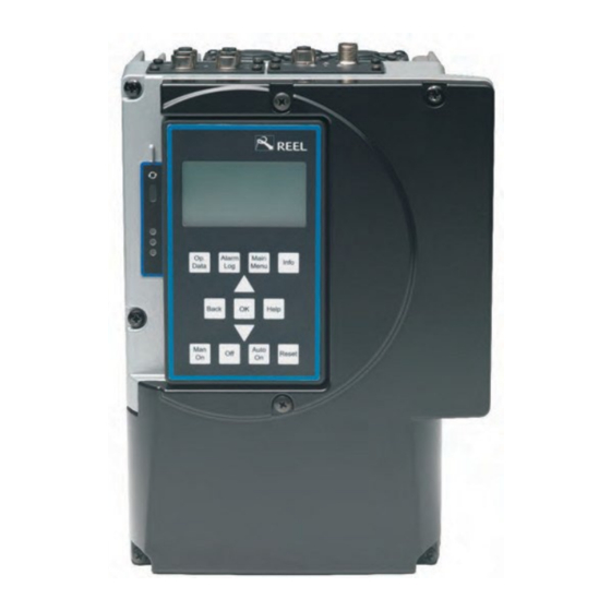
5 Product specifications 5.8 Description of the graphic keypad (optional) Figure 7: Description of the graphic keypad Rif. Description Function Displays the operating information relating to the frequency Display converter Press to go to the elements of the first menu level: - Operation - Diagnosis Menu keys... -
Page 26: Converter Dimensions, Weights And Fixings
5 Product specifications 5.9 Converter dimensions, weights and fixings Figure 8: Dimensions Table 21: Converter dimensions, weights and fixings Fixing Model Weight(kg) (mm) (mm) (mm) (mm) (mm) screw (F) F0K37 F0K55 M4 x 10 F0K75 DIN912 F1K10 F1K50 F2K20 F3K00 M4 x 10 F4K00 DIN912... -
Page 27: Intended Use
Place of use hindered. The product can even be used in aggressive environments, not necessarily in an electric cabinet. Intended use To control a standard electric motor or a REEL SuPremE vector motor ® Authorised operators meeting the professional technical requirements Installers described in par. -
Page 28: Residual Risks
5 Product specifications WARNING 1) Do not modify product. Doing so will void the warranty. 2) Do not connect non-original spare parts, equipment and/or accessories to the product. 3) Do not clean the product with flammable liquids or solvents. 5.12 Residual risks The Manufacturer informs operators that although all possible technical- construction protective measures have been taken to make the product safe, residual risks still remain. -
Page 29: Personal Protective Equipment (Ppe)
5 Product specifications RESIDUAL RISK NO. 5 Crushing and entanglement hazard: due to the automatic startup of the product, if authorised operators use the product improperly and fail to comply with the following guidelines: The appropriate PPE must be worn at all times (see par. 5.13). ... -
Page 30: Tools
5 Product specifications Table 23: Personal protective equipment - PPE Mandatory PPE for all authorised operators GLOVES (To protect hands against direct contact when working live or close to live parts 1000 V - EN 60903:2003) GLOVES (For protection against heat) ELECTRICALLY INSULATING FOOTWEAR (To protect the wearer against electric shock when working live or close to live parts EN 20344:2004/A1:2007, EN 20347:2004/A1:2007, EN 50321:1999) -
Page 31: Automatic Differential Thermal-Magnetic Circuit Breaker At Line Inlet
5 Product specifications Table 24: Recommended fuses Recommended fuses FlexiMova Ampere rating ® Input Inom t (25°C) MaX. Size and power (kW) Size A (0,35 – 1,5) 1,4 – 5,2 6/16 Size B (2,2 - 3 - 4) 6,3 – 10,4 16/25 Size C (5,5 -11) 14,6 –... -
Page 32: Transportation - Storage - Disposal
6 Transportation – Storage - Disposal 6 Transportation - Storage - Disposal 6.1 Packaging Upon delivery of the goods check every package to verify that there are no visible signs of damage. The packaging enclosure, when the product is supplied separately as a separate non-assembled element, must be intact and dry. -
Page 33: Disposal
• Motor mounted with an adapter (specific for REEL SuPremE motors). ® • Motor mounted (also on motors other than REEL SuPremE ) using the ® purpose-made adaptation KIT (not available as an optional). FlexiMova mm - Design and Installation ®... -
Page 34: Wall Or Machine Mounted
7 Mounting instructions of the converter 7.2.1 Wall or machine mounted A KIT (optional) is available for wall/machine mounting, consisting of metal plate and brackets that are fixed to the product to enable installation. Figure 10, Figure 11 and Figure 12 illustrate the three different KIT models, differentiated by the size of the product. -
Page 35: Motor Mounted
Figure 13: Example of the FlexiMova mm converter mounted directly ® on the REEL SuPremE® motor. The REEL SuPremE® motors also require an outlet that allows them to connect to the product: For sizes A and B: fitting for quick connector (see Figure 15), ... - Page 36 ® The REEL SuPremE® motors also require an outlet to enable connection that is suitable for the converter in use. In this case for REEL SuPremE® motors connecting to sizes A and B a quick connector arrangement will be fitted as illustrated below.
- Page 37 7 Mounting instructions of the converter For sizes C, D, E the arrangement is an internal cable passage fitted at the rear of the radiator which will couple directly to the adapter provided for fixing to the motor. Remember to remove the protective cover. Figure 16: Example of cable passage in sizes C, applicable also to sizes D and E Figure 17: Hole diameter Size C: ø...
-
Page 38: Direct Mounting On Reel Supreme® Motor Fitted With Traditional Terminal Box By Means Of Mechanical Adapter Plate
7 Mounting instructions of the converter 7.2.3 Direct mounting on REEL SuPremE® motor fitted with traditional terminal box by means of mechanical adapter plate This type of mounting is a specific installation for REEL SuPremE motors fitted ® with a traditional terminal box (supplied as standard) which is used for the electrical connection to the motor. -
Page 39: Electrical Connections
8 Electrical connections 8 Electrical connections 8.1 Electromagnetic compatibility 8.1.1 Classification The product is designed in compliance with the EMC Directive 2014/30/UE “Electromagnetic Compatibility” in accordance with the reference standard EN 61800-3 which in turn refers to EN 55011 for the part relating to electromagnetic emissions. -
Page 40: Inverter - Motor Power Connections
8 Electrical connections The shield of the signal cable must only be connected on the converter side with its ground terminal. If the signal cable is particularly long (longer than 20 m) connect the shield at both ends. No signal cables must be arranged parallel to the power cables and they ... - Page 41 RWK 305- 156-KS 156-KS (*)REEL’s tests are carried out with the cable and ferrites declared in the table; equivalent components can be used. (**)For connections with cables longer than 50 m the installer is responsible for selecting the most suitable solutions and for verifying the classification achieved.
-
Page 42: Safety Measures Relating The Electrical Connection
8 Electrical connections The Manufacturer suggests various solutions to cover possible problems. The system designer selects the most suitable solution and/or alternative components with similar characteristics to those suggested. Output line reactor: is mandatory for installations with long cables ... -
Page 43: Selecting And Laying The Power Cables
8 Electrical connections 8.3 Selecting and laying the power cables The choice of connecting cables depends on various factors including the type of connection, the environmental conditions and the type of system. The connecting cables must comply with regulations, and selected with particular attention to: manufacturer’s details, rated voltage, insulation class, rated current, operating temperature and thermal effects. - Page 44 8 Electrical connections Figure 19: Connection to the AC power supply network PE, L1, L2 and L3 connection PE, U, V and W inlet for shielded for the mains cable motor cable Motor cable shield connection Size the connecting cables to the mains supply network with a section suitable for the rated current plus an additional amount for greater distances or higher temperatures.
- Page 45 8 Electrical connections Table 29: Connection to the AC mains supply network AC and to the motor Type of Type of Rated input Section of Minimum and Size and Power cable gland motor cable current input cable maximum cable Model (kW) used in the required...
-
Page 46: Installation Of Line Impedance And Network Filters
8 Electrical connections 8.3.2 Installation of line impedance and network filters The input reactor is built-in to reduce harmonic distortion and to ensure it falls within the declared category. As well as the built-in input impedance in the frequency converter (included in the power range up to 55 kW) it is possible to use external network impedance to further reduce the harmonic distortion. - Page 47 8 Electrical connections Table 30: Table for the selection of the 3-phase input line reactors Power Inductance Rated current MAX saturation Size (kW) Ln (mH) In (A) current Isat (A) F0K37 0.37 F0K55 0.55 1,5 In F0K75 0.75 F1K10 F1K50 F2K20 1,5 In F3K00...
-
Page 48: Motor Connecting Cables
8 Electrical connections 8.3.3 Motor connecting cables The cables for the connection of the motor must be shielded cables with adequate insulation. The ground connection must be made to both the motor and the converter by means of the connection in the terminal block. The various sizes of the FlexiMova®... -
Page 49: Length Of The Motor Connecting Cables
8 Electrical connections 8.3.4 Length of the motor connecting cables If the frequency converter is not mounted directly on the motor longer connecting cables may be necessary. Using cables that are longer than the maximum permissible length, it can cause the internal protections to trip as all the cables have parasitic capacitance existing between the various conductors, due to the parallel arrangement and close proximity to the shield. -
Page 50: General Wiring Diagram Of The Various Sizes Of The Fleximova ® Mm
8 Electrical connections 8.4 General wiring diagram of the various sizes of the FlexiMova ® 8.4.1 Layout of power terminal block Size A Figure 23: Connection size A Output connector DC +/‐and Brake In‐line connector Motor output connector PE, U, V and W PE, L1, L2 and L3 Motor PTC connector... -
Page 51: Layout Of Power Terminal Block Size B
8 Electrical connections 8.4.2 Layout of power terminal block Size B Figure 24: Connection size B Motor PTC Motor output connector Output connector In‐line connector connector PE, U, V and W DC +/‐and Brake PE, L1, L2 and L Shield connections Denomination Denomination Mains connection... -
Page 52: Layout Of Power Terminal Block Size C
8 Electrical connections 8.4.3 Layout of power terminal block Size C Figure 25: Connection size C Motor output Hole for the motor Motor PTC connector PE, mounting passage connector U, V and W In‐line connector PE, L1, L2 and L3 Output connector Internal DC +/‐and Brake... -
Page 53: Layout Of Power Terminal Block Size D
8 Electrical connections 8.4.4 Layout of power terminal block Size D Figure 26: Connection size D Hole for the passage of motor cables In‐line connector Output connector Motor output Motor PTC PE, L1, L2 and L3 DC +/‐and Brake connector PE, connector U, V and W Shield connections... -
Page 54: Layout Of Power Terminal Block Size E
8 Electrical connections 8.4.5 Layout of power terminal block Size E Figure 27: Connection size E Hole for the passage of motor cables Output connector In‐line connector Motor output Motor PTC DC +/‐and Brake PE, L1, L2 and L3 connector PE, connector U, V and W Shield connections... -
Page 55: Ground Connection
8 Electrical connections The connection of both the shield and the ground wire of the motor cable must be made at both ends, that is, at the inverter end (using the dedicated fixings) and at the motor end. The shield must have a coverage of at least 80% of the cable’s length and it must be connected directly to the structure by means of the screws provided (see Figure 28). -
Page 56: Selecting The Signal Connecting Cable
8 Electrical connections 8.5 Selecting the signal connecting cables 8.5.1 Removing the cover from the product DANGER The Manufacturer informs operators that although all possible technical- construction protective measures have been taken to make the product safe possible residual risks Nos. 2 and 3 still remain (see par. 5.12). WARNING It is prohibited to remove the central part of the heatsink. -
Page 57: Terminal Blocks
8 Electrical connections 8.5.2 Terminal blocks Table 32: Designation of the terminal blocks Figure 29 - No. Designation Power board terminal block Control board terminal block Table 33: Control board terminal block Terminals Signal Description Technical characteristics ON ≥ 15 ÷ 30 VDC Safety Hardware Channel OFF ≤... -
Page 58: Signal Cable
8 Electrical connections 8.5.3 Signal cable Always use shielded cables for the signal connections. The shield must have a coverage of at least 80% of the cable length. The shield can be connected directly to the structure of the converter by means of the fixings provided (see Figure 30). -
Page 59: Description And Examples Of Connections To The Terminal Block Of The Control Board
8 Electrical connections 8.5.4 Description and examples of connections to the terminal block of the control board Digital inputs The product has 6 digital inputs (DI1...DI4, DI-STO, HW-STO). The digital inputs DI-STO and HW-STO are reserved solely for Safe- Torque-Off function whereas the functions of the digital inputs from DI1 to DI4 can be programmed as desired. - Page 60 8 Electrical connections Figure 31: Example of connection with +24 V power supplied by the converter - total available power MAX. 500 ma, MAX. 150 ma for each output. Safety Stop input HW-STO Safety feedback input DI-STO Configurable digital inputs DI1 - DI4 Configurable analog output AO1 Configurable analog input AIN1 and AIN2:...
- Page 61 8 Electrical connections Figure 32: Example of connection with connection with external +24 V power supply Safety Stop input Reference HW-STO External signal for speed reference Safety feedback input DI-STO Configurable digital inputs DI1 - DI4 Configurable analog output AO1 Configurable analog input AIN1 and AIN2: 10‐0‐10 V/ 0‐10 V / 4‐20 mA / 0‐20 mA...
-
Page 62: Converter Wiring Diagram
8 Electrical connections 8.5.5 Converter wiring diagram The product is provided with fixing points for the ground wire and the power and signal shield. Figure 33: Example of standard connection of a single converter Shielded signal cable Shielded power cable with power ground Unshielded cable conductor for connection to motor at power supply... -
Page 63: Breaking Resistor
8 Electrical connections 8.6 Braking resistor 8.6.1 Guidelines for selecting the braking resistor See Table 34 for the selection of the resistor (value and power). Use insulated cables suitable for the voltage that can reach values up to 840 VDC. For the braking resistor connection see par. -
Page 64: Connection Of The Braking Resistor
8 Electrical connections 8.6.2 Connection of the braking resistor If the application requires the use of the braking resistor (requiring dynamics or rapid decelerations) the product must be connected as illustrated in Figure 34, and comply with the resistance values specified for each size. -
Page 65: Sizing The Braking Resistor
8 Electrical connections 8.6.3 Sizing the braking resistor Table 34: Braking resistor information table FlexiMova MAX. ® Minimum MAX. braking braking Braking MAX. FlexiMova ® Power Rated resistor value resistor Current Current Size (kW) current (A) (Ω) ower (kW) F0K37 0.37 F0K55 0.55... -
Page 66: Configuration Of The Converter For It Network
9 Configuration of the converter for IT 9 Configuration of the converter for IT network The IT network is also commonly referred to as “isolated power supply ” as the star point of the IT power supply is not grounded. This type of power supply uses an isolation controller that constantly monitors the galvanic isolation between the ground and the various powered parts. - Page 67 9 Configuration of the converter for IT Figure 37: IT configuration for size C Jumper IT network Size C (2 Jumpers present J1 and J2) Inserted= standard TN network Removed = IT network Figure 38: IT configuration for size D Jumper IT network Size D (2 Jumpers present...
-
Page 68: Fleximova ® Mm Version With Electrolytic Capacitors
10 FlexiMova mm version with electrolytic capacitors ® 10 FlexiMova mm version with electrolytic capacitors ® ATTENTION The FlexiMova mm converter version with electrolytic capacitors for sizes ® A, B, C must be OFF when being installed. ATTENTION Be sure to connect FlexiMova mm converter version with electrolytic ®... - Page 69 10 FlexiMova mm version with electrolytic capacitors ® Connection is by means of the cable glands provided and the +/- DC connection present on the terminal block: Figure 40: FlexiMova mm version with electrolytic capacitors ® Connection NOTE: Red wire (+) terminal , Black wire (-) terminal Denomination Denomination Mains connection...
-
Page 70: Capacitor Box For Size A
Figure 41: Capacitor box for size A version without connector (dimensions in mm) Figure 42: Capacitor box for size A version mounted on the motor with connector provided for adapter (dimensions in mm) (Only for REEL SuPremE® motors ) 70 of 80 FlexiMova mm - Design and Installation... -
Page 71: Capacitor Box For Size B
Figure 43: Capacitor box for size B version without connector (dimensions in mm) Figure 44: Capacitor box for size B version mounted on the motor with connector provided for adapter (dimensions in mm) (Only for REEL SuPremE® motors ) FlexiMova mm - Design and Installation ®... -
Page 72: Capacitor Box For Size C
Figure 45: Capacitor box for size C version without adaptor (dimensions in mm) Figure 46: Capacitor box for size C version mounted on the motor with connector provided for adapter (dimensions in mm) (Only for REEL SuPremE® motors ) 72 of 80 FlexiMova mm - Design and Installation... -
Page 73: Mechanical Mounting Of The Capacitor Box Sizes A And B
Figure 47: Motor connection via cable gland outlet and traditional terminal block Connection NOTE: DC connection Red wire (+) terminal Black wire (-)terminal (Only for REEL SuPremE® motors ) FlexiMova mm - Design and Installation ® 73 of 80... - Page 74 Figure 48: Motor connection via motor cable to the connector on the converter. Plugs directly into the motor adapter. Connection NOTE: DC connection Red wire (+) terminal Black wire (-)terminal (Only for REEL SuPremE® motors ) 74 of 80 FlexiMova mm - Design and Installation ®...
-
Page 75: Mechanical Mounting Of The Capacitor Box For Size C
Figure 49: Standard connection without connector Connection NOTE: DC connection Red wire (+) terminal Black wire (-)terminal (Only for REEL SuPremE® motors ) FlexiMova mm - Design and Installation ® 75 of 80... - Page 76 10 FlexiMova mm version with electrolytic capacitors ® Capacitor box with connector mounted on a REEL SuPremE® motor . In this case the capacitor box is connected to the product via both the outgoing DC cables from the box, and via the motor cable that plugs into the connector on the converter.
-
Page 77: Connection Layout Of The Capacitor Box For Sizes A And B
10 FlexiMova mm version with electrolytic capacitors ® 10.6 Connection layout of the capacitor box for sizes A and B Figure 51: Capacitor box for sizes A and B 10.7 Connection layout of the capacitor box for size C Figure 52: Capacitor box for size C FlexiMova mm - Design and Installation ®... -
Page 78: Sizes D And E: Version With Electrolytic Capacitors
® 10.8 Sizes D and E: version with electrolytic capacitors This version must be selected at the time the order is placed with REEL so that it can be purpose-built from the beginning. For all the converters with electrolytic capacitor version (see par. 10.9). -
Page 79: Accessories For Mounting The Converter
Wall mount KIT for size B Wall mount KIT for size C Wall mount KIT for size D Wall mount KIT for size E KIT for mounting on REEL SuPremE® motor with standard terminal box FlexiMova mm - Design and Installation ®... -
Page 80: Accessories For Communication And Available Optional Extras
10 FlexiMova mm version with electrolytic capacitors ® 10.9.3 Accessories for communication and available optional extras Table 37: Accessories for communication and available optional extras Name / Description Image Infrared communication module Graphic keypad operator interface ModBus RTU communications board for installation in SLOT 1 ProfiBus DPV10 communications board for installation in SLOT 2 Profinet communications board for installation in SLOT 2 Ether CAT* communications board for installation in SLOT 2... - Page 84 REEL S.r.l. a Socio Unico Via Riviera Berica 40/42 36024 Ponte di Nanto (VI) Italy...
Need help?
Do you have a question about the FlexiMova mm Series and is the answer not in the manual?
Questions and answers