
Related Manuals for SIUI CTS-900

Summary of Contents for SIUI CTS-900
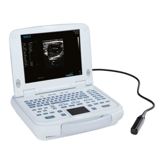
- Page 1 DCY2.782.900SS/V6.0/A-E CTS-900 Digital Ultrasound Imaging System OPERATION MANUAL...
-
Page 3: Table Of Contents
CONTENTS Preface …………………………………………………………………………………… III Application Scope, Operation Conditions, Safety and Cautions…………. 1-1 Application Scope……………………………………………………………..Operation Conditions……………………………………………………………..Power Requirements……………………………………………………………..Safety……………………………………………………………......Cautions……………………………………………………………......Classification…………………………………………………………..... 2. System Composition, Principle and Specification…………………………… 2-1 System Composition and Operation Principle…………………………………. Specification….…………………………………………………………………… Introduction to Components………………………………………………..3-1 System Configuration……………………………………………………………… Introduction to Component Parts…………………………………………………. - Page 4 Search Disk Directory……………………………………………………………... Print Image………………………………………………………………………….. 10. Maintenance, Troubleshooting, Transport and Storage………………………. 10-1 10.1 System Maintenance………………………………………………………………. 10-1 10.2 Troubleshooting……………………………………………………………………. 10-1 10.3 Contact Information of SIUI Service Department……………………………... 10-3 10.4 Transport and Storage Condition………………………………………………… 10-3 10.5 Disposal……………………………………………………………………………... 10-3 Appendix A: Abbreviation……………………………………………………………… A-1 Appendix B: Touchpad Function Indication……………………………………….
-
Page 5: Preface
Preface Preface To use this system correctly and safely and to ensure a long life, the user should thoroughly understand the functions, operations, instructions as well as its maintenance. Please read the information in this manual carefully before using the system. This system has been designed and manufactured safely for the operators and patients. - Page 6 Preface Manual. The company reserves the final right to interpret this Operation Manual.
-
Page 7: Application Scope, Operation Conditions, Safety And Cautions
Application Scope, Operation Conditions, Safety and Cautions Chapter 1 Application Scope, Operation Conditions, Safety and Cautions 1.1 Application Scope The system is a general-purpose diagnostic ultrasound imaging system designed exclusively for use in a wide variety of extracorporeal body imaging procedures. A general-purpose system supports various transducers and related application software packages allowing for the collection, display and analysis of ultrasound information. -
Page 8: Power Requirements
Application Scope, Operation Conditions, Safety and Cautions The system must be separated from such emission sources or electromagnetic waves. c) Do not operate this system while other devices are operating with motor or silicon controlled switch in the same power phase; otherwise, noise will disturb your system through power cable. -
Page 9: Safety
Application Scope, Operation Conditions, Safety and Cautions total load of all devices consisting of the system, or it may result in danger. Tip: In regions where mains supply is not stable, it is recommended to use power supply from a stabilizer with output power of 120VA, so as to avoid damage to the system due to mains fluctuation. -
Page 10: Cautions
Application Scope, Operation Conditions, Safety and Cautions connected to a supply mains with protective earth. 1.5 Cautions a) While operating the system, please follow the methods and procedures described in this manual; b) Always turn off the system and protect it with a dust-proof cover whenever the system is not in use;... - Page 11 Application Scope, Operation Conditions, Safety and Cautions For instructions on probe disinfection and protection, follow the description in 4.2.9; It is prohibited to scan eyes with the probe. Keep the acoustic power as low as reasonably achievable (ALARA). Scan the body only in a period required for making the diagnosis, rather than scan the body for a long time.
-
Page 12: Classification
Application Scope, Operation Conditions, Safety and Cautions s) Multiple devices, when interconnected, might result in accumulative leakage current and dangers; Make sure to use the special components provided by SIUI for system component repair or replacement. patient shield sheet To the equipoten-... -
Page 13: System Composition, Principle And Specification
System Composition, Principle and Specification Chapter 2 System Composition, Principle and Specification 2.1 System Composition and Operation Principle 2.1.1 System Composition The system consists of a main unit, a probe and peripheral devices. The main unit includes Probe Interface Board, Order and Amplification Board, Digital Processing Board, Control Platform, Operation Panel, LCD Monitor, Power Supply and Battery. -
Page 14: Specification
System Composition, Principle and Specification ultrasound. The echo of the ultrasound from human body is received by the same working elements and converted into feeble echo electrical signals, which will be transmitted to the Order and Amplification Board through front-end amplification. There is one-probe connector available on the Probe Interface Board, to which one probe can be connected. - Page 15 System Composition, Principle and Specification 2.2.3 Probe (Basic Configuration): Multiple frequency convex probe. 2.2.4 Focus Method: a) Transmitting focusing method: 1 ~ 4 transmitting focus(es) for selection, 16 focusing positions for selection; b) Receiving focusing method: Continuous dynamic focusing. 2.2.5 Grayscale: 256 2.2.6 Beam-forming Method: Digital beam forming, continuous dynamic focusing, dynamic aperture, dynamic apodization.
- Page 16 System Composition, Principle and Specification 2.2.15 Body Mark: more than 90 body marks for selection, with probe mark. 2.2.16 Annotation: not less than 300 system predefined annotations. 2.2.17 System Preset. 2.2.18 Image Screen Display: a) Display all the parameters related with diagnosis: system model, hospital name, patient name, patient ID, date, time and week, probe model, exam type, and probe orientation;...
- Page 17 System Composition, Principle and Specification 2.2.22 Monitor: LCD monitor. 2.2.23 Probe Connector: 1 pc. 2.2.24 System Operating Condition 2.2.24.1 Electrical Requirements a) AC-DC Adapter: Power input: 100V-240V~, 50 Hz /60Hz. Max. current 0.35A under 220V~, (or max. current 0.7A under 110V~).
-
Page 18: Introduction To Components
Introduction to Components Chapter 3 Introduction to Components 3.1 System Configuration 3.1.1 Basic Configuration a) Main Unit (including battery): 1pc b) Probe: Multiple frequency convex probe: 1 pc. 3.1.2 Accessories a) Power adapter; b) Battery charger; c) BNC/RCA cable; d) Printer control cable; e) Special charger power cable (for connection with car cigarette lighter);... -
Page 19: Introduction To Component Parts
Introduction to Components 3.1.4 Connection to Peripheral Devices a) Video printer (SONY UP-897MD video printer is recommend), video tape recorder (VCR) and big-screen monitor, which can be connected to the main unit via a cable with a BNC plug; b) USB printer (Model HP LaserJet 1015 is recommended), which can be connected to the main unit via a USB port. - Page 20 Introduction to Components 3.2.1.2 Probe Application a) The probe may be damaged even by a slight impact. Use it carefully to avoid shocking or striking against any hard object; b) Ensure that the main unit is in frozen state (it would be better to turn off the power of the main unit.) while connecting or disconnecting probe;...
- Page 21 Introduction to Components This control bar is on the operation panel. 1—LCD monitor; 2—Power in symbol: When the system is supplied by external power, it displays a power symbol . If the system is supplied by the battery, it displays a battery symbol and indicates the current power capacity;...
- Page 22 Introduction to Components 3.2.2.2 Display Interface Probe orientation mark Current frame/total frame Date/time SIUI Facility Name Day of the week (Cineloop state) System Model Probe (Model) Frame Depth B Gain Freq SPAN B GSC Angle Current Exam type Body function...
- Page 23 Introduction to Components 3.2.3 Operation Panel 3.2.3.1 Features of Operation Panel The arrangement of the operation panel is shown in Fig. 3-5, and the functions of each key are described as follows. Fig. 3-5 Operation Panel 3.2.3.2 Brief Introduction of Keys Freq ( a) Probe frequency switch key: Exam (...
- Page 24 Introduction to Components angle can be adjusted by pressing . Press key again to cancel the display of the Biopsy guidelines. g) Positioning midline display key ): it is used to enable/disable the positioning midline. In Focus state of B Mode, press key, and the positioning midline will be displayed on the screen;...
- Page 25 Introduction to Components Meas Calc u) Measurement menu recall keys: Enter v) Confirmation key: w) Exit key: Text ANNOT x) Annotation key: y) Alphanumeric keys: keys on top left of the operation panel. ( ); Caps Lock z) Capital letter and small letter shift key: )...
- Page 26 Introduction to Components 3.2.4 Rear Panel (see Fig. 3-6) 1— USB Port; 4—Network Port; 2— Print Control Port; 5—Heat Dissipation Fan; 3— Video Out Port; 6—External DC Power In Port. Fig. 3-6 Rear Panel Note: External DC power-in port is for connection with special DC power supply, then either a battery in the battery compartment or not is acceptable.
-
Page 27: Installation, Inspection And Maintenance
Installation, Inspection and Maintenance Chapter 4 Installation, Inspection and Maintenance 4.1 System Installation 4.1.1 Load and Unload, Charge, and Usage of the Battery The battery for this system is a special rechargeable polymer lithium-ion battery. Its detailed specifications are as follows: a)... - Page 28 Installation, Inspection and Maintenance charging of the battery can be divided into 2 situations: Meaning of charger indicator: red for charging, and green for charging completed. 【 】 a) Battery charging with AC power supply internal charging Install the battery on the system. When the ultrasound system is connected to AC power supply, the battery will be charged: 1) If the ultrasound system is in off or dormant state, it takes 3~4 hours for a battery fully used up to become fully charged;...
- Page 29 Installation, Inspection and Maintenance different capacity, model or type; o) If the battery is leakage or gives off peculiar smelling, move the battery away from open flame, because leaked electrolyte may cause fire or explode. p) Do not use the battery if it is in peculiar smelling, heats, distortion, changed color or any other abnormity.
-
Page 30: Inspection And Maintenance
Installation, Inspection and Maintenance position of the plug with the slot of the system socket as shown in Fig. 4-2. When disconnecting the DC power plug, hold the plug and pull it out as shown in Fig. 4-3. Note: The system might be damaged if you do not follow item e) to operate the system. - Page 31 Installation, Inspection and Maintenance Inspect whether the input and output ports are loose. 4.2.7 Regular safety inspection The following safety inspections should be carried out by an experienced, well-trained qualified person at least every 24 months: Inspect if the equipment and the accessories are damaged in mechanics and functions.
- Page 32 Installation, Inspection and Maintenance b) The immersion part of the probe should not exceed the orientation mark at the probe housing side; c) Do not process the probe with steam high-pressure or ethane oxide; d) Do not immerse the probe for more than one hour. 4.2.9.1 Cleaning a)...
-
Page 33: System Setup
System Setup Chapter 5 System Setup 5.1 Operation Method for System Setup Menu Menu Value Press to display the system main menu on the screen. Use the touchpad or Enter control key ( to select desired menu item; press to enter the submenu;... - Page 34 System Setup 5.2.2 System Setup submenu Table 5-2 System Setup Menu Menu Description Date Time To set up date and time Facility Name To set up facility (hospital) name AC Power Unit To switch the acoustic power display unit TGC curve To set up TGC curve display modes Key Lamp To set up keyboard backlight...
- Page 35 System Setup 1) Three formats supported by the system for displaying date are available, including YYYY/MM/DD, MM.DD.YYYY and DD-MM-YYYY. Set up Date format: Enter Press after selecting Date Format, then the Date format can be set by Enter pressing repeatedly to toggle among the three optional formats. 2) There are two formats supported by the system for displaying time, including 24 hours display format, and 12 hours plus AM/PM display method.
- Page 36 System Setup Backspace inputted content or to clear the characters one by one. 5.2.2.3 AC Power Unit There are 2 units dB and % available for selection. To enter selection menu, select AC Enter. Power Unit on the system setup menu and press To select the desired unit, move Enter the cursor and press...
- Page 37 System Setup 5.2.2.10 Language Selection Two languages for displaying on the screen are available, including English and Chinese. To enter the selection menu, select Language Selection on system setup menu and then Enter press . Its operation process is the same as setup of AC Power Unit. 5.2.2.11 Patient Information There are 2 selections Hide and Show available for the setup of patient information.
- Page 38 System Setup shown in Fig. 5-1. The contents of application type and exam type change according to the selection of the user. Press to exit the current setup screen and return to the previous level of menu without saving. Fig. 5-2 Edit Screen of Annotation Press Initialize to clear all the user self-defined annotation phrases of the current exam type.
- Page 39 System Setup There are two methods available to access the edit interface of User-definded Gray Curve shown in Fig. 5-3. Fig. 5-3 Edit Interface of User-definded Gray Curve Menu a) Method 1: Press on the keyboard to enter the system menu. Select Image Enter Setup and press to display the submenu Image Setup.
- Page 40 System Setup Enter position is displayed close to +) to the desired position and press to make a point of the selected position. You can also input values into the edit box to draw out a gray curve. b) Delete: Move the cursor to the desired point on the edit box and press to delete Backspace this point;...
- Page 41 System Setup Yes and No are available for selection. If Yes is selected, when the image is unfrozen, the annotations (including text and non-text annotations) on the imaging area will be cleared. If No is selected, when the image is unfrozen, the annotations will remain on the imaging area.
- Page 42 System Setup PSAD Coefficient To set up Prostate Specific Antigen Density coefficient Fetal Growth Curves Edit To edit fetal growth curves Fetal Age Estimating Select To choose fetal age table Fetal Age Estimating Edit To edit fetal age table Measurement Line Type To set up Calc/Meas line type Display OB Measurement To display OB Measurement Traces...
- Page 43 System Setup proportionality coefficient can be inputted. 5.2.5.10 Fetal Growth Curves Edit Enter Select Fetal Growth Curves Edit on the calculation setup submenu and press enter the edit screen of BPD Growth Curve Table shown in Fig. 5-4. Fig. 5-4 Edit Screen of BPD Growth Curve Table Value a) To select other types of growth curve tables: press control key.
- Page 44 System Setup submenu of that menu item will be popped up for user selection. See the second column of Table 5-7. Select Table to calculate based on data in fetal age table; select Equation to calculate with an equation. Table 5-7 Fetal Age Estimating Menu Menu Submenu Hadlock Equation, Hadlock Table, Hansmann Table,...
- Page 45 System Setup Fig. 5-5 Edit Screen of BPD Fetal Age Estimating Edit The default equation displayed is BPD Fetal Age Equation. Other fetal age equations can Value be selected by rotating control key. The value of a~e and Coff is changeable and the equations in Fig.5-5 will be changed accordingly.
- Page 46 System Setup 5.2.5.14 Display OB Measurement Traces It is used to set up whether to display all the measured traces in OB measurement. There are two options for selection: All is to display all measured traces, Current is to display the current measured trace, and the other measured traces may be enabled by adjusting Value key.
- Page 47 System Setup Fig. 5-7 Dialog Box for File Selection Enter c) Delete file: Select Open Files and press . After selecting Save image or Enter Clear Text Open file, press and select the desired file to be deleted. Press to delete the file. 5.2.6.2 NetWork NetWork is for sharing information between the local system and a remote system.
- Page 48 System Setup Fig.5-8 Input Box for Query Condition 【Note】: Make the DICOM operation directory under the DcmDir directory in the hard disk directory. In the disk management state, the user can operate the DcmDir directory and the files in the directory and does not need to create a new file folder.
- Page 49 System Setup local system. Input an AE name of the remote system that corresponds to the IP address in the AE edit box. Finally, input the port number of the remote system (the IP address, the AE name and the port number can be found in Local of the remote Enter system).
- Page 50 System Setup 【Note】: Before upgrading the system, please ensure that the main unit has sufficient power supply to complete the upgrade process. It is strongly recommended that the power adapter be used during upgrade, so as to avoid system failure due to abrupt power breakdown in this process.
-
Page 51: Imaging
Imaging Chapter 6 Imaging 6.1 Preparation 6.1.1 Tools a) Connect the probe to the probe socket (please pay attention to the assembly orientation of probe connector) and fix the probe firmly; b) Check the battery; c) Connect the external special power if necessary; d) Unfold the front panel;... - Page 52 Imaging The scanning frequency of each probe is wide and changeable, and can be toggled Freq according to the diagnostic requirements. In unfrozen state, press key, to change the frequency of the current probe. There are several frequencies available for selection. T-Ball In unfrozen state, press key to switch the touchpad function to control window.
- Page 53 Imaging of 11 characters. On the exam type management interface, the character U is attached on the exam type defined by the user. On the exam type management interface, operations listed in Table 6-2 are defined for user selection. Table 6-2 Hotkeys for Exam Type Menu Operation Hotkey Function...
- Page 54 Imaging 6.2.2.4 Exam Type Menu 6.2.2.4.1 Composition of Exam Type Menu (Fig. 6-1) a) Probe model: Probe model is displayed on the first line of the exam type menu. b) Application type: The current application name is displayed under the probe model; the cursor will rest on the application type after entering the exam type menu.
-
Page 55: Preliminary Imaging
Imaging finish the loading and save. The hotkey can be used to delete a user-defined exam type. Press this key after selecting an exam type to be deleted. The system will prompt whether to delete that exam Enter Enter type or not. Select SET then press to confirm, or select Cancel then press to cancel deletion. - Page 56 Imaging b) While a probe is placed on an exam area, an image will appear on the monitor immediately. 6.3.2 Selection of Display Mode The system has display modes including B, 2B, 4B, B/M and M. B Mode Enter In unfrozen state, the user can press mode keys, or for selection B Mode...
- Page 57 Imaging All the keyboard operations can only be conducted on the active image. If a frozen B image is released, this image will adopt the control parameters in the current control-box, and the other B image will be frozen simultaneously. Rotation In 2B mode, press to press the real-time image by 180°.
-
Page 58: Adjusting Image
Imaging 6.3.3 Moving M Mode Image Sampling Line In unfrozen state, you can press to enter B/M mode. The M mode image sampling line will be displayed automatically on the B mode image, and it can be moved left or right by operating the touchpad towards left or right. - Page 59 Imaging at this moment, all the focuses will be shifted up or down accordingly. If select SPAN in the control window, the system will enter the span setting state; press Value control key to change the span between focal points. 6.4.3 Setting persistence T-Ball In unfrozen state, press...
- Page 60 Imaging sweeping speed. Four speeds are available, including 1.25, 2.5, 5.0, and 10.0 (second/frame). 6.4.9 IP One-key-optimization Function When the current state is Focus, M LINE or Wcont in unfrozen state, press to load the first group of optimal parameters (which is prompted over the imagine area) and the image changes accordingly.
-
Page 61: Changing Image Display Range
Imaging 6.4.11 Line Density Two options for adjusting line density are available: High and Low. 6.5 Changing Image Display Range 6.5.1 Adjusting Display Depth To adjust the image display depth, press control display depth key unfrozen state. The Display depth will be decreased while pressing , and increased while pressing ;... - Page 62 Imaging Enter position have been set, press and the image within the zoom box is zoomed in. Now the magnified image area can be moved by using the touchpad. Press to show or hide the zoom box. Zoom During image zoom in, press again to return to the initial state of zoom, or directly press to exit the zoom state.
- Page 63 Imaging In unfrozen state, you can press to reverse the image positive/negative. The power-on setup is positive (black background and white characters). 6-13...
-
Page 64: Annotation Of Image Information
Annotation of Image Information Chapter 7 Annotation of Image Information Inputting Patient Information 7.1.1 Description of Functions The information such as patient’s NAME, ID, AGE, SEX, HEIGHT, WEIGHT, LMP, PSA, etc, can be inputted into the system and saved in the database (ID is a must). 7.1.2 Operation Method Pat Data... - Page 65 Annotation of Image Information existing information in the input area, move the cursor with the touchpad to the input area to be modified. Having modified the information, select Set and press Enter to complete modification. Pat Data c) Clear: Press key to bring up the Patient Information Interface.
-
Page 66: Adding Annotation On Image
Annotation of Image Information 7.2 Adding Annotation on Image 7.2.1 Function Description The user can add texts and annotations on a frozen image. Once the image is unfrozen, the annotation will be automatically removed. Text function allows the user to input characters and numbers;... - Page 67 Annotation of Image Information ANNOT In order to add an annotation, press key to enter annotation state, then the preset annotation phrases set according to the diagnostic part will be displayed in the list. Enter Use the touchpad to select the desired annotation (highlighted display) and press Then the selected annotation, which is now in gray, will be shifted with the cursor.
- Page 68 Annotation of Image Information Table 7-2 Predefined Annotations for GYN Table 7-3 Predefined Annotations for Urology Uterus Ovary Kidney BLADDER Prostate UTERUS LEFT RIGHT BLADDER PROSTATE RIGHT FOL 1 O RRA LONG LEFT R OV FOL 2 P RRA ENDOME FOL 3 M RRA URETHRA...
- Page 69 Annotation of Image Information Table 7-5 Predefined Annotations for Cardiology Adult cardiology Adult diff cardiology Pediatric cardiology AORTIC AORTIC AORTIC TCHZ TCHZ TCHZ AO ROOT AO ROOT AO ROOT MITRAL MITRAL MITRAL PEAK PEAK PEAK R ATRIUM R ATRIUM R ATRIUM ASC AO ASC AO ASC AO...
- Page 70 Annotation of Image Information LONG VITREOUS BODY TESTICLE CORONAL THYROID MEDIAL LENS HYDROCELE 4TH VENT ISTHMUS CYST RETINA TRANS R KID RT LOBE LATERAL OPTIC DISK LONG LENS OPTIC NERVE SPLEEN INFERIOR SUPERIOR MASS LAT VENT THROAT TAIL CYST LT LOBE AXILLA CAVUM PARA...
-
Page 71: Body Mark
Annotation of Image Information VEIN LEFT ULNAR A Predefined annotations for orthopedics are: THIGHBONE HEAD, HIPBONE and ACETABULUM. Predefined annotations for Podiatry are: LEFT, RIGHT, LONG, TRV, PLANTAR, FASCIA, ACHILLES TENDON, PT TENDON, TENDON, NEUROMA, CALCANEUS, INJECTION. 7.3 Body Mark Body marks are a group of pictorial diagrams of patient organs. - Page 72 Annotation of Image Information a) Abdomen Body Marks Fig.7-3 Abdomen Body Marks b) Cardiology Body Marks Fig.7-4 Cardiology Body Marks c) Gynecology Body Marks Fig.7-5 Gynecology Body Marks d) Obstetrics Body Marks...
- Page 73 Annotation of Image Information Fig.7-6 Obstetrics Body Marks e) Peripheral Vessel Body Marks Fig.7-7 Peripheral Vessel Body Marks Urology Body Marks Fig.7-8 Urology Body Marks g) Small Part Body Marks 7-10...
- Page 74 Annotation of Image Information Fig.7-9 Small Part Body Marks h) Orthopedics Body Marks Fig.7-10 Orthopedics Body Marks Podiatry Body Marks Fig.7-11 Podiatry Body Marks 7-11...
-
Page 75: Measurement And Calculation
Measurement and Calculation Chapter 8 Measurement and Calculation The user can do measurement on ultrasound images and obtain various results based on different calculation methods; these results will be automatically and simultaneously entered into reports for the user to generate diagnostic reports. 8.1 Key and Menu for Measurement &... - Page 76 Measurement and Calculation To confirm the Meas/Calc item while measuring & calculating. Enter To switch and confirm LMP input in growth charts. To select options in Report. To exit the current Meas/Calc and go to the previous menu, or exit directly. The direct measurement keys can be used to measure distance and Area...
- Page 77 Measurement and Calculation %diam. Reduce Diameter reduction percentage Histogram Histogram LDW-vol. LDW-vol. After entering Histogram calculation screen, a transparent rectangular box (80X80 pixels), which can be moved within the image range by using the touchpad, appears in the image central position. The box is resizable by using the control key (see Section 8.3.4 Value for detailed description on Histogram).
- Page 78 Measurement and Calculation Long L Lobe Long Diameter of Left Lobe A-P L Lobe Antero-posterior Diameter of Left Lobe Angle L Lobe Angle of Left Lobe Obli. R Lobe Oblique of Right Lobe A-P R Lobe Antero-posterior Diameter of Right Lobe Angle R Lobe Angle of Right Lobe Portal Vein...
- Page 79 Measurement and Calculation Left Renal Artery Long Diameter of Right Kidney L R Kidney Antero-posterior Diameter of Right Kidney A-P R Kidney Transversal Diameter of Right Kidney T R Kidney Right Ureter R Ureter Right Renal Artery Long Diameter of Bladder Long Blad Antero-posterior Diameter of Bladder A-P Blad...
- Page 80 Measurement and Calculation A-P IG Antero-posterior Diameter of Internal Gland Trans IG Transversal Diameter of Internal Gland L L Semi Vesi Long Diameter of Left Seminal Vesicle A-P L Semi Vesi Antero-posterior Diameter of Left Seminal Vesicle T L Semi Vesi Transversal Diameter of Left Seminal Vesicle L R Semi Vesi Long Diameter of Right Seminal Vesicle...
- Page 81 Measurement and Calculation fetal echo and multi gestations. They have different calc menus. In Table 8-9, items from the first one to Report or Biophy Profile are calc menus in B mode; items from Report to Heart Rate are for M mode; and the calc menus in B/M mode combines all the above items.
- Page 82 Measurement and Calculation Heart Rate Heart Rate Complete OB menu Biparietal Diameter Head Circumference Abdominal Circumference Femur Length Gestational Sac Crown Rump Length Amniotic Fluid Index Amniotic Fluid Index Amniotic Fluid Index Amniotic Fluid Index Occipito-Frontal Diameter Trans-Abdominal Diameter Antero-posterior Abdominal Diameter Humeral Length Tibial Length Ulnar Length...
- Page 83 Measurement and Calculation Left Ventricular Outflow Tract LVOT Pulmonary Artery Right Ventricular Outflow Tract RVOT Left Atrium Right Atrium Left Ventricle Right Ventricle Inter-ventricular Septum ARCH Aortic Arch Superior Vena Cava Inferior Vena Cava LV AREA Left Ventricle Area RV AREA Right Ventricle Area Cardiac Diameter Thoracic Diameter...
- Page 84 Measurement and Calculation Fetus2 LV Lateral Ventricle Fetus2 HW Hemisphere Width EFW2-Shepard Estimated Fetal Weight -Shepard’s Method EFW2-Hadlock1 Estimated Fetal Weight -Hadlock’s Method 1 EFW2-Hadlock2 Estimated Fetal Weight -Hadlock’s Method 2 EFW2-Hadlock3 Estimated Fetal Weight -Hadlock’s Method 3 EFW2-Hadlock4 Estimated Fetal Weight -Hadlock’s Method 4 EFW2-Campbell Estimated Fetal Weight –Campbell’s Method EFW-Hansmann...
- Page 85 Measurement and Calculation 8-10; there is only Report in M mode. Table 8-10 Small Parts Calc Menu Menu Description Thyroid Long L Lobe Long Diameter of Left Lobe AP L Lobe Antero-posterior Diameter of Left Lobe Trans L Lobe Transversal Diameter of Left Lobe SUPA L Lobe Superior Artery of Left Lobe INFA L Lobe...
- Page 86 Measurement and Calculation Testis Long L Testis Long Diameter of Left Testis AP L Testis Antero-posterior Diameter of Left Testis Trans L Testis Transversal Diameter of Left Testis Long Diameter of Left Epididymis Long L Epidi AP L Epidi Antero-posterior Diameter of Left Epididymis Long R Testis Long Diameter of Right Testis AP R Testis...
- Page 87 Measurement and Calculation Report Report Carotid artery submenu Diameter Diameter Intima Intima Mean-IMT Intima-media complex thickness Area-T Area-T Area-E Area-E %D Reduce %Diameter reduce %A Reduce %Area reduce Peripheral artery menu Left AXIA Left Axillary Artery Right AXIA Right Axillary Artery Left BRAA Left Brachial Artery Right BRAA...
- Page 88 Measurement and Calculation 8.1.3.7 Cardiology Calculation Cardiology application includes three exam types: adult cardiology, adult difficult cardiology and pediatric cardiology. They have the same calculation menu. Menu items change accordingly with modes. See Table 8-12. Table 8-12 Cardiology Menu Menu Description B mode menu RVAW...
-
Page 89: Display And Clear Of Meas/Calc Result
Measurement and Calculation a) Patient Information in reports cannot be edited (except for pressing key). Pat Data b) Gestation Age and Estimated Date of Delivery are calculated automatically based on the result of LMP and measurement. c) Relevant measurement result will be displayed in the report if the user does certain measurement. -
Page 90: Operation Of Meas/Calc
Measurement and Calculation the display position. To modify completed Meas result, press key and then key, and press Meas Enter control key to move the cursor over a certain measurement result to start a new Value measurement. 8.2.2 Clear Meas/Calc Result To clear Meas/Calc result, press key in Meas/Calc state or single-frame Clear Text... - Page 91 Measurement and Calculation 8.3.2 Area/Circumference 8.3.2.1 Trace method Fig. 8-2 Area/Circumference Measurement and Result with Trace Method In the frozen state in B, 2B, 4B or B/M mode, press key to measure the area and Area the circumference of the selected part on the image. Entering area measurement screen, a + cursor will appear in the center of the image.
- Page 92 Measurement and Calculation In B, 2B, 4B or B/M mode, press key and a menu will appear. Select Ellipse-area Meas in the menu to enter ellipse method area measurement screen. A + cursor will appear on the screen. Use the touchpad and press key to fix the start point of the long axis.
- Page 93 Measurement and Calculation image (plane R in Fig. 8-4); then acquire the max. transversal plane in the other image (plane L in Fig. 8-4) , then freeze the image. Press key and select Biplane-vol. to Meas enter the measurement screen of biplane volume. A + cursor shows up on the screen. Use the touchpad to place the + on the start point of the longitudinal diameter on plane R and press .
- Page 94 Measurement and Calculation displayed in two lines in the result area. 8.3.3.4 Simpson-vol. In Simpson-vol., the enclosed area acquired by Trace method is divided into several equal parts (5 pixels apart here) along the long axis. Each part is regarded as a volume of a cylinder for calculation the volume.
- Page 95 Measurement and Calculation In B mode, histogram of a desired area can be acquired by calculation. Press Meas to enter measurement menu. Select Histogram and enter histogram calculation screen. A transparent rectangular frame will appear in the center of the image. There is a result box of histogram at the bottom right of the image.
- Page 96 Measurement and Calculation In M or B/M mode, press and select Heart Rate to enter heart rate measurement Meas screen. “aBeat number: × , aHR: 0.00bpm“ is displayed in result area. Other operation is the same as Time measurement. 8.3.7 Slope Fig.
- Page 97 Measurement and Calculation screen, for example b and c. Press and select to enter angle measurement ∠ ∠ ∠ Meas screen. A + cursor will appear on the screen. Operate the touchpad to move the cursor to the start point of the first line and press .
- Page 98 Measurement and Calculation displayed in three lines in the measuring result area. b) Hadlock1 method: Hadlock1 method estimates fetal weight by the measured AC and FL. Enter EFW-Hadlock1. “Weight: g GA: xxWxxD EDD: Y/M/D“ is displayed in three lines in the measuring result area. c) Hadlock2 method: Hadlock2 method estimates fetal weight by the measured AC, FL and HC.
- Page 99 Measurement and Calculation b) In Basic OB, Complete OB and Mult Gest exam types in obstetrics application, press key to select BPD, HC, AC, FL and EFW for measurement. Calc c) After completing measurement, press , select Growth Charts and press Calc Growth chart menu will appear in the screen center.
- Page 100 Measurement and Calculation Fig. 8-10 Screen of Growth Chart 8.3.9.5 Biophy profile When the exam type is Basic OB, Complete OB, Fetal Echo or Mult Gest, press Calc and select Biophy profile. Press to enter biophy profile screen. Enter a) Move cursor: press control key to shift the cursor up and down among Value input boxes.
- Page 101 Measurement and Calculation + cursor is fixed. Point B will be shown. Operate the touchpad to move the + cursor to the position corresponding to point B. Input points B to I in order. Meas/calc value of AO measurement will be displayed in the measuring result area. As Points A~I are displayed in pairs on their vertical dotted lines, the cursor can only be moved up or down (rather than left or right) along the positions of points A, C, E and H when fixing points B, D, F, G and I .
- Page 102 Measurement and Calculation displayed in the measuring result area. Fig. 8-13 Initial, Final and Result Page of TV measurement 8.3.10.4 PV measurement Fig. 8-14 Initial, Final and Result Page of PV measurement PV is Pulmonic Valve measurement in frozen state in M or B/M mode. Enter PV measurement.
- Page 103 Measurement and Calculation positions of points C and G, when fixing points D~F and points H~J. The Meas/Calc result is displayed in seven lines in the measuring result page. Fig. 8-15 Initial, Final and Result Page of LV measurement 8.3.10.6 LV function Select LV FUNC in menu to calculate left ventricle function based on LV Calc...
- Page 104 Measurement and Calculation 8.3.12 Measurement of Bladder Volume The measurement of bladder volume is similar to Biplane-vol, however, the former shall be performed in 2B mode only. Here are the operation steps: In 2B mode unfrozen state, acquire the max. longitudinal plane in one image window (plane R);...
-
Page 105: Cineloop, Image Storage And Print
Cineloop, Image Storage and Print Chapter 9 Cineloop, Image Storage and Print 9.1 Cineloop In B, 2B or 4B mode unfrozen state, images will be stored continuously into memory. After the image is frozen, the stored images can be played back in frames. Operate the touchpad will enable viewing the images in the memory saved before the image is frozen. -
Page 106: File Storage
Cineloop, Image Storage and Print will be stored permanently in the hard disk. Please refer to Section 9.3.4 for the detailed setup. After the image is successfully stored, the system screen will prompt “Saved Successfully”. 9.2.2 Quickly Recall an Image Recall After the image is frozen, press key to enable recall and review of the stored... - Page 107 Cineloop, Image Storage and Print Fig. 9-2 In the review screen, hotkeys can be used to operate the files. The hotkey functions are shown in Fig. 9-3. Fig. 9-3 9.3.4 Store Settings To set up default file format, store location, etc. when store quickly. Fig.
- Page 108 Cineloop, Image Storage and Print Folder Format refers to the store location of patient data in the Local storage. For example, if Folder Format is Date, a folder named after the current date will be created by the system and the patient data will be stored in this folder. e) Save/Recall Location Save Set the image store location by setting up the...
- Page 109 Cineloop, Image Storage and Print system screen will prompt “Saved Successfully”. 【Note 1】: If in the report screen, the save format can only be bmp or jpg. 【Note 2】: If want to save a cine file, select cine/avi/cts format. The files in avi format can be played on the PC, but images with M-mode display cannot be saved in avi format;...
-
Page 110: Search Disk Directory
Cineloop, Image Storage and Print Enter Delete: select Delete and press . The cursor jumps to the path dialog box. Enter Select the image file to be deleted, and then press . The system will prompt whether to delete that file (see Fig. 9-7). Now press to cycle switch the cursor Enter between OK and Cancel;... -
Page 111: Maintenance, Troubleshooting, Transport And Storage
Maintenance, Troubleshooting, Transport and Storage Chapter 10 Maintenance, Troubleshooting, Transport and Storage 10.1 System Maintenance Every time before operating the system, the user should inspect the probe cable connector, the probe cable, the potential balance lead, and the power cord carefully to check whether there is any separated sheath, shedding, or other signs of damage on them. - Page 112 Statement: Circuit schematics and component list may be provided to SIUI approved qualified service personnel for equipment maintenance. WARNING: No modification of this equipment is allowed.
-
Page 113: Contact Information Of Siui Service Department
Maintenance, Troubleshooting, Transport and Storage 10.3 Contact Information of SIUI Service Department Address: Shantou Institute of Ultrasonic Instruments Co., Ltd. (SIUI) #77 Jinsha Road, Shantou, Guangdong 515041, China Tel: 86-754-88250150 Fax: 86-754-88251499 E-mail: siui@siui.com or service@siui.com 10.4 Transport and Storage Condition a) Ambient temperature range: -40℃... -
Page 114: Appendix A Abbreviation
Abbreviation Appendix A Abbreviation :The third cerebral ventricle %A Redu: Area reduce percentage % D Redu: Diameter reduce percentage AC: Abdominal circumference AC: Anterior chamber A-C: The time from A point to C point AOD: Aortic diameter AFI: Amniotic fluid index AO: Aorta AOAMP: Aortic posterior wall amplitude A-P: Anterior-posterior... - Page 115 Abbreviation E-E: Height from E point to E’ point EF: Ejection fraction EFW: Estimated fetal weight EPSS: E peak separation to septum ESV: End-systolic volume FIBL: Fibular length FL: Femur length Grow Chart: Growth Chart GS: Gestational sac HC: Head circumference HL: Humeral length HR: Heart rate HW: Hemisphere width...
- Page 116 Abbreviation L ICA: Left Internal carotid artery L Kidney: Left Kidney LL: Lower lateral L Lobe: Left Lobe L LV: Left lateral ventricle Long: Long Diameter L Ovary: Left Ovary L POPA: Left popliteal artery LRA: Left renal artery L RADA: Left radial artery L Testis: Left Testis L ULNA: Left ulnar artery L Ureter: Left ureter...
- Page 117 Abbreviation P Grade: Placenta grade Prost: Prostate PV: Portal vein PV: Pulmonic valve PV A: The depth of A peak RA: Right atrium R AXIA: Right axillary artery R BRAA: Right brachial artery R Breast: Right breast RCCA: Right common carotid artery R DORA: Right dorsal artery R ECA: Right external carotid artery R Eye: Right eyeball...
- Page 118 Abbreviation S-I: Superior-inferior diameter SMA: Superior mesentery artery Splenic A: Splenic artery Splenic V: Splenic vein SUPA: Superior artery SV: Stroke volume TAD: Trans-Abdominal diameter TAU: Transversal diameter after urination TD: Thoracic diameter TL: Tibial length Trans: Transversal diameter TV: Tricuspid valve UI: Upper internal UL: Upper lateral UL: Ulnar length...
-
Page 119: Appendix B Touchpad Function Indication
Touchpad Function Indication Appendix B Touchpad Function Indication Current mode Touchpad control object Indication Focus depth Focus B mode unfrozen Control window display item WCont B mode frozen Scroll: display from frame to frame Scroll M line position M LINE B/M mode unfrozen Control window display item WCont... -
Page 120: Appendix C Description Of Symbol
Description of Symbol Appendix C Description of Symbol Number Symbol IEC publication Description 878-02-03 Type BF Applied Part 878-03-01 Caution, risk of electric shock 417-5019 Protective conductor terminal 417-5017 Earth (ground) terminal 417-5021 Equipotentiality 417-5032 Alternating current 417-5008 Off(supply) 417-5007 On(supply) ISO 7010-M002 Refer to instruction manual/ booklet... -
Page 121: Appendix D Acoustic Output Parameter
Acoustic Output Parameter Appendix D Acoustic Output Parameter Transducer Model:C3I60H Operating Mode:M Index Label Non-scan Non- Scan scan ≤1cm² >1cm² aprt aprt 0.924 0.060 0.202 0.091 Global Maximum index value 1.687 rα Min.of[P α ta,α Associated Acoustic 2.90 parameters z at max. I 2.95 pi,α... - Page 122 Acoustic Output Parameter Transducer Model:C3I60H Operating Mode:B Index Label Non-scan Non- Scan scan ≤1cm² >1cm² aprt aprt Global Maximum index value 0.845 0.278 0.635 1.523 rα Min.of[P α ta,α Associated Acoustic parameters z at max. I 4.05 pi,α 3.244 3.244 3.244 Dim of 1.92...
- Page 123 Acoustic Output Parameter Transducer Model:C5I20H Operating Mode:M Index Label Non-scan Non- Scan scan ≤1cm² >1cm² aprt aprt Global Maximum index value 0.682 0.065 0.128 0.078 1.489 rα Min.of[P α ta,α Associated Acoustic parameters z at max. I 1.65 pi,α 0.433 4.712 4.712 4.442...
- Page 124 Acoustic Output Parameter Transducer Model:C5I20H Operating Mode:B Index Label Non-scan Non- Scan scan ≤1cm² >1cm² aprt aprt Global Maximum index value 0.700 0.177 0.743 1.507 rα Min.of[P α ta,α Associated Acoustic parameters z at max. I 2.65 pi,α 4.635 4.635 4.635 Dim of 1.20...
- Page 125 Acoustic Output Parameter Transducer Model:L7I38H Operating Mode:M Index Label Non-scan Non- Scan scan ≤1cm² >1cm² aprt aprt Global Maximum index value 0.527 0.127 0.186 0.153 1.363 rα Min.of[P α ta,α Associated Acoustic 1.44 parameters z at max. I 1.60 pi,α 0.250 6.683 6.683...
- Page 126 Acoustic Output Parameter Transducer Model:L7I38H Operating Mode:B Index Label Non-scan Non- Scan scan ≤1cm² >1cm² aprt aprt Global Maximum index value 0.865 0.308 0.764 2.201 rα Min.of[P α ta,α Associated Acoustic parameters z at max. I 2.32 pi,α 6.48 6.48 6.48 Dim of 0.84...
- Page 127 Acoustic Output Parameter Transducer Model:U5I50H Operating Mode:M Index Label Non-scan Non- Scan scan ≤1cm² >1cm² aprt aprt Global Maximum index value 0.911 0.097 0.141 0.106 2.052 rα Min.of[P α ta,α Associated Acoustic parameters z at max. I 2.80 pi,α 0.462 5.078 5.078 5.078...
- Page 128 Acoustic Output Parameter Transducer Model:U5I50H Operating Mode:B Index Label Non-scan Non- Scan scan ≤1cm² >1cm² aprt aprt Global Maximum index value 0.641 0.242 0.688 1.445 rα Min.of[P α ta,α Associated Acoustic parameters z at max. I pi,α 5.087 5.087 5.087 Dim of 1.17 0.60...
- Page 129 Acoustic Output Parameter Transducer Model:V6I11H Operating Mode:M Index Label Non-scan Non- Scan scan ≤1cm² >1cm² aprt aprt Global Maximum index value 0.875 0.125 0.156 0.141 2.239 rα Min.of[P α ta,α Associated Acoustic 0.50 parameters z at max. I 0.95 pi,α 0.462 6.541 6.541...
- Page 130 Acoustic Output Parameter Transducer Model:V6I11H Operating Mode:B Index Label Non-scan Non- Scan scan ≤1cm² >1cm² aprt aprt Global Maximum index value 0.744 0.295 0.442 1.851 rα Min.of[P α ta,α Associated Acoustic parameters z at max. I 1.85 pi,α 6.193 6.193 6.193 Dim of 0.66...
- Page 131 Range,_Precision_and_Accuracy_of_AdjustmentDisplay_Parametersr Appendix E Range, Precision and Accuracy of Adjustment/Display Parameters The system Range, Precision and Accuracy of Adjustment/Display Parameters are shown in the following table: Adjustment/ Range Precision Accuracy Display Parameter Depth 3.2cm~25.2cm 1.58cm ≥95% B_Gain 0~100 ≥90% 0~100 ≥90% ≥95% SPAN ≥95%...
- Page 133 Shantou Institute of Ultrasonic Instruments Co., Ltd. Address: #77 Jinsha Road, Shantou, Guangdong 515041, China Tel: 86-754-88250150 Fax: 86-754-88251499 Http: //www.siui.com E-mail: siui@siui.com EC REP Name: Shanghai International Holding Corp.GmbH(Europe) Address: Eiffestrasse 80,20537 Hamburg Germany 0123 October 2011...
Need help?
Do you have a question about the CTS-900 and is the answer not in the manual?
Questions and answers