
Summary of Contents for Electrolab 2110EX-A
- Page 1 USER MANUAL Explosion Proof Housing - Analog Model 2110EX-A EL29300 Version V.000 Last Updated: 01/2022 © 2022, Electrolab, Inc. All Rights Reserved.
- Page 2 Electrolab, Inc. reserves the right to revise this publication and to make changes from time to time in its content without the obligation to notify any person or organization of such revision or changes.
-
Page 3: Special Warnings
I/O lines for devices located in Hazardous Areas. Functions: The 2110EX-A is capable of delivering safe levels of supply power and 2-wire RS485 digital signals to a device located in Class I Division 1 location and also provides two 4-20mA(3 wire configuration) analog signal output channels. - Page 4 Document # EL29300 Version: V.000 USER MANUAL Communication analog output lines (X1-2 and X1-3): Voltage: 5 VDC nom / 24 VDC max Output current: Maximum: 50 mA max - fuse limited Normal operation range: 0 to 20mA 24 VDC (Should be supplied only from NRTL-listed limited power supply) Environmental Conditions: Temperature: Operating...
-
Page 5: Terminal Connections
Document # EL29300 Version: V.000 USER MANUAL TERMINAL CONNECTIONS Table 1. EXPLOSION PROOF CONNECTION INTRINSICALLY SAFE CONNECTION X1-L1 → GND J1-1 → Tx/Rx+ X1-L2 → I2 J1-2 → DC_GND X1-L3 → I1 J1-3 → Tx/Rx- X1-L4 → +VCC J1-4 → VDC X1-L5 →... -
Page 6: Jumper Settings
Document # EL29300 Version: V.000 USER MANUAL ENTITY PARAMETERS TABLE Table 2. Terminals 2110EX Parameter Must Hazardous Area Device Parameters ≤ J1-4 = 11.655 V ≤ J1-1 thru J1-4; = 233.96 mA ≤ J1-1 thru J1-4; = 0.596 W ≥ J1-1 thru J1-4;... -
Page 7: Led Assignments
Output bottom level on I2 WARNING: Never change jumper settings while device power is on. LED ASSIGNMENTS The 2110EX-A has 4 LEDs on board : Red – assigned to current loop 1 (X1-L3) status Green – assigned to DLS2100 sensor communication status Blue –... - Page 8 J6 jumper setting(see Table 6 above). If J6 is set for bottom level the scale for this loop is set at the device start up when 2110EX-A read from the DLS2100 level sensor the following parameters min_4mA –...
- Page 9 Not to be connected to control equipment that uses or generates more than 24VDC with respect to earth ground. The 2110EX-A must be installed, operated, and maintained only by qualified personnel, in accordance to relevant national/international installation standards (National Electric Code (NFPA, Article 504) and ANSI/ISA –...
-
Page 10: Installation
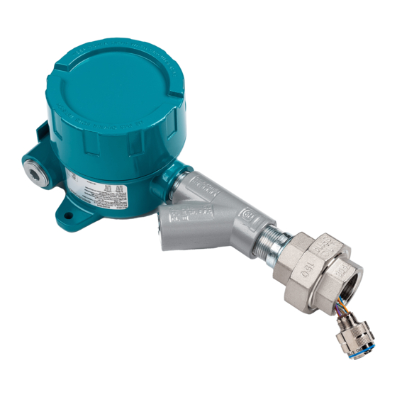
USER MANUAL MARKING Labels: The Model 2110EX-A will be clearly marked on the label attached to the enclosure, label drawing number is 2110EX-A-00. Serial Number: For each PCB board a unique serial number will be generated after factory testing. The serial number consists of five digits (e.g. - Page 11 2110EX-A connector with 6 pins 4. Apply thread sealant to the 1-inch NPT connector on the sensor. 5. Hold the 2110EX-A above the sensor flange connector with one hand; insert and tighten up the connector to the sensor with the other hand.
- Page 12 USER MANUAL Tighten connector 6. Unscrew the bottom part of the union from the 2110EX-A. Then screw the bottom part of the union‘s 1-inch FNPT onto the sensor‘s 1-inch MNPT flange until hand tight. Make sure the connector cable is not caught in the threads or joint. Tighten the union using a 1.5“ wrench but do not overtighten.
-
Page 13: Control Drawing
Document # EL29300 Version: V.000 USER MANUAL CONTROL DRAWING Page 13 of 15... - Page 14 Document # EL29300 Version: V.000 USER MANUAL Page 14 of 15...
- Page 15 Document # EL29300 Version: V.000 USER MANUAL For more information contact Electrolab: Electrolab, Inc. 159 Enterprise Parkway Boerne, Texas 888-301-2400 www.electrolabcontrols.com Page 15 of 15...
Need help?
Do you have a question about the 2110EX-A and is the answer not in the manual?
Questions and answers