Advertisement
Available languages
Available languages
Quick Links
ALMAG Active
Pulsed Electromagnetic Field Therapy Device
ALMAG Active
Magnettherapiegerät
ALMAG Active
Appareil de magnétothérapie
ALMAG Active
Dispositivo per terapia magnetica
ALMAG Active
Aparato magnetoterapéutico
ALMAG Active
Urządzenie magnetoterapeutyczne
ALMAG Active
Magnetoterapijos prietaisą
English
Deutsch
Français
Italien
Español
Polish
Lithuanian
2
58
114
170
226
282
338
Advertisement
Chapters

Related Manuals for DENAS ALMAG Active


Summary of Contents for DENAS ALMAG Active
- Page 1 ALMAG Active English Pulsed Electromagnetic Field Therapy Device ALMAG Active Deutsch Magnettherapiegerät ALMAG Active Français Appareil de magnétothérapie ALMAG Active Italien Dispositivo per terapia magnetica ALMAG Active Español Aparato magnetoterapéutico ALMAG Active Polish Urządzenie magnetoterapeutyczne ALMAG Active Lithuanian Magnetoterapijos prietaisą...
- Page 2 DEAR CUSTOMER, Congratula ons! You have just purchased ALMAG Ac ve Pulsed Electromagnet- ic Field Therapy Device (hereina er – Device). The Device is classifi ed as medical equipment product and is listed in the nomenclature of physiotherapeu c devices authorized for use in medical prac ce.
- Page 3 Symbolic notations on the device Warnings and precautions related to safety and operating efficiency. Type BF working part. The working part of the device is protected with reinforced insulation. The mark defines the device as complying to Class II in terms of electrical safety according to IEC 60601-1. Operating Manual.
-
Page 4: Table Of Contents
TABLE OF CONTENTS 1. WARNINGS AND SAFETY INSTRUCTIONS ............6 2. PURPOSE AND OPERATING PRINCIPLE ............... 9 3. SCOPE OF DELIVERY ................... 11 4. INDICATIONS FOR USE ..................11 5. CONTRAINDICATIONS ..................12 6. SIDE EFFECTS ...................... 14 7. PREPARATION FOR USE ..................15 8. - Page 5 - facial nerve neurtis ..................38 - radial nerve neuritis ..................39 - ulnar nerve neuritis ..................40 - median nerve neuritis .................. 40 - sciatic nerve (ischias) neuritis ..............40 - peroneal nerve neuritis ................41 - plexitis ......................42 - neuralgia ......................
-
Page 6: Warnings And Safety Instructions
1. WARNINGS AND SAFETY INSTRUCTIONS Please, read this Opera ng Manual prior to proceeding with medical or prophy- lac c procedures using the device. To protect the device from damage, keep it out of the reach of children if unsupervised. Visually inspect the device before you start performing treatment. - Page 7 Precautions for therapeutic use: Use the device in locations where control unit can be comfortably connected to the socket and cable tension can be avoided during operation. DO NOT: • use the device with mechanically damaged control unit housing and/or control unit cable and/or inductor coils;...
- Page 8 Important electromagnetic compatibility (EMC) information Since electronic devices like PCs and mobile (cell) phones become increasingly popular, medical equipment in use may be sensitive i.e. it interferes with electromagnetic noise generated by other devices. Electromagnetic interference may impair the operation of the medical device and create a potentially unsafe situation.
-
Page 9: Purpose And Operating Principle
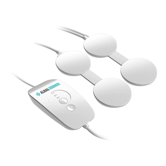
2. PURPOSE AND OPERATING PRINCIPLE The device is intended to provide physiotherapeu c treatment as well as recov- ery and rehabilita on measures using a low-frequency pulsed magne c fi eld, either in medical facili es or at home, upon the recommenda on of a doctor. The device consists of the control unit (current pulse generator) and an emi er comprising four interconnected inductor coils used to provide exposure to individ- ual parts of the body. - Page 10 Matrix layout of the inductor coils Inductor coils are combined into two groups of two coils per group. The groups may be confi gured in the form of 2x2 matrix and/or «spline» composed of four inductor coils. «Spline» emi er confi gura on is achieved using corresponding fas- tener included in delivery.
-
Page 11: Scope Of Delivery
3. SCOPE OF DELIVERY • ALMAG Active Pulsed Electromagnetic Field Therapy Device • Accessories: Spline fastener Strap Magnetic field indicator • Operating Manual • Retail package 4. INDICATIONS FOR USE Musculoskeletal system diseases: - osteochondrosis - humeroscapular periarthrosis - osteoarthritis... -
Page 12: Contraindications
- radial nerve neuritis - ulnar nerve neuritis - median nerve neuritis - sciatic nerve (ischias) neuritis - peroneal nerve neuritis - plexitis - neuralgia - trigeminal neuralgia - occipital neuralgia - intercostal neuralgia Pancreatic diabetes complications: - diabetic angiopathy - diabetic polyneuropathy Diseases of venous system: - deep vein thrombosis of the lower leg... - Page 13 • malignancies*; • condi ons preven ng from procedure performing: alcohol and drug intoxica- on, psychomotor agita on of any genesis; • uncompensated arterial hypertension of Class 3, arterial hypertension crisis of any class; • arterial hypotension (SBP < 90 mm Hg, DBP < 65 mm Hg); •...
-
Page 14: Side Effects
6. SIDE EFFECTS In order to avoid adverse events including increase in arterial blood pressure and comorbid diseases, do not exceed the exposure me as specifi ed in the Direc ons for Use Chapter of this Opera on Manual, defi ned in sec ons «General rules of pro- cedure sequence»... -
Page 15: Preparation For Use
7. PREPARATION FOR USE In case the device was transported or stored for a long me at temperatures below 10 °С, fi rst keep it at least 2 hours at a temperature in between 10 °С and 35 °С before turning on. Ensure that there is no mechanical damage to the cable and the housing of the device. -
Page 16: Operation Procedures
8. OPERATION PROCEDURES 8.1. General rules of procedure sequence A en on! Before treatment start, carefully read the list of indica ons and con- traindica ons and be sure to consult your doctor to determine the correct diagnosis and to exclude your exis ng diseases and condi- ons contraindica ng the use of the device. - Page 17 • The dura on of the procedure and the treatment modes is determined indi- vidually taking into account the pa ent’s age. The recommended combina ons of the procedure dura on and treatment mode are indicated in sec on «Fea- tures of the methodology of device use in various age categories of pa ents».
- Page 18 • When using the device for its intend- ATTENTION! ed purpose, pay a en on to the correct When performing procedures, placement of the emi er on the body: locate the emitter with the all the methods s pulate for ac ng by working surface of inductors the north magne c pole of the inductor with the «N»...
- Page 19 A en on! It is not recommended at the same me (on the same day) to treat two diff erent diseases. A en on! In case the exposure results in the blood pressure increase or de- crease by 10 to 25 mm Hg during the fi rst 6 days of treatment (Mode 3), reduce the treatment dura on by 1/3 during the next ses- sion and apply Mode 2 during the next 3 days of treatment.
- Page 20 When using the four inductor coils confi gured in the form of «spline», the spline fastener (herea er the fastener) is required. The fastener fi xes the coils together preven ng them from traveling rela ve to each other. Place the inductor coils into the fastener stepwise according to the «spline» ar- rangement as follows: •...
- Page 21 • Place the rest 1 and 2 inductor coils into the fastener and fi x them with velcros. • Zip up the fastener. OPERATING MANUAL...
- Page 22 • Four inductor coils are now arranged in the form of «spline». • Use the accessory straps delivered with the device to fi x the «spline» to the extremi es. Locate the straps over the zipper and fi x them with velcros. Where 2х2 matrix inductor coil confi...
- Page 23 Connect the power cord of the device to the 230 V power network outlet. A en on! Locate the device at the site comfortable for use. Avoid tension of power cord and emi er cable. Only use working (fault-free) power socket.
-
Page 24: Treatment Modes
8.2. Treatment Modes Set the desired exposure mode using the «Mode Select» bu on switch. The desired mode is selected by pressing the «Mode Select» bu on (Mode 1 – Mode 2 – Mode 3 – Mode 1) in sequence, and a sound signal is heard repeatedly where the number of repe ons corresponds to the mode number. - Page 25 The treatment is ini ated and terminated by pressing the «START/ STOP» bu on and is accompanied by sound signal and non-fl ashing glow of the «START/STOP» bu on LED indicator. The exposure (treatment dura on) is set automa cally to 20 minutes for all the treatment modes.
- Page 26 Once the exposure is completed (or terminated forcedly), the «START/STOP» bu on LED indicator blinks off and the sound signal is heard. A er the comple - on of the treatment, the device waits for 5 minutes and then switches to standby mode.
-
Page 27: Age-Specific Dosage Prescriptions
8.3. Age-specific dosage prescriptions Applying treatment to pa ents over 15 years old During the treatment, the procedure dura on and the treatment mode are cho- sen in accordance with Table 2. Table 2. Course treatment procedure of patients over 15 years old Treatment day Mode Interruption/Break... - Page 28 Table 3. Course treatment procedure for patients at the age of 4 weeks to 1 year old Treatment day Mode Duration (min.) Treatment day Mode Duration (min.) Table 4. Course treatment procedure for patients 1 to 3 years old Treatment day Mode Duration (min.) Treatment day...
- Page 29 Table 5. Course treatment procedure for patients 3 to 7 years old Treatment day Mode Duration (min.) Treatment day Mode Duration (min.) Table 6. Course treatment procedure for patients 7 to 15 years old Treatment day Mode Duration (min.) 10-12 10-12 10-12 10-12...
-
Page 30: Inductors Application To Deliver Disease-Specific Procedures
8.4. Inductors application to deliver disease-specific procedures Musculoskeletal system diseases: • ОSTEOCHONDROSIS Locate the inductor coils pairwise in parallel along the spine over the long back muscles in such a way that the vertebrae of concern are between the inductor coils (see Figure 1). -
Page 31: Humeroscapular Periarthrosis
In case of osteochondrosis complicated by radicular syndrome, the treatment is first applied onto the affected area of the spine, after which the device must be turned off, wait for 10 minutes, a line of emitters is installed along the affected nerve covering the nerve root and treat the second area, as shown in Figure 3. -
Page 32: Osteoarthritis
• OSTEOARTHRITIS In case of osteoarthritis of one joint, a line of four inductors is spirally wrapped around the joint covering the surrounding tissue as shown in Figure 5. If it is necessary to treat two knee joints, one pair of inductors is applied to one affected joint, the second pair to the second, as shown in Figure 6. - Page 33 If the hip joint is damaged, a line of four emitters is placed on the projection of the hip joint from the inguinal region through the large trochanter of the tibia (the most protruding part) to the sacral region, as shown in Figure 8. In case of bilateral lesion of hip joints, the procedures are carried out alternately on one and another joints.
-
Page 34: Epicondylitis
• ЕPICONDYLITIS The inductor coils are located around the injured joint. In case of shoulder epicondylitis, the inductor coils are applied around the joint, as shown in Figure 10. With epicondylitis of the shoulder joint, in order to increase the treatment effectiveness, the device should act on two areas alternately. -
Page 35: Injuries And Their After-Effects: - Bone Fractures
Injuries and their after-effects: • BONE FRACTURES IMPORTANT! In case of bone fracture, the treatment with the device is started on the 3 or 5 day from the injury occurence. The inductor coils are installed on a plaster cast or directly on a limb during traction, along or around the bone, as shown in Figures 12 and 13. -
Page 36: Internal Joint Injuries
• INTERNAL JOINT INJURIES IMPORTANT! In case of hemarthrosis (presence of blood in the joint cavity), the procedures are carried out only after removal of blood from the joint cavity, as directed by the doctor. A line of four inductors are spirally wrapped around the injured joint covering the surrounding tissue, as shown in Figures 14 to 18. -
Page 37: Posttraumtic Edema
• POSTTRAUMTIC EDEMA IMPORTANT! The treatment by the device is started no earlier than 12 hours from the moment of the occurence of the injury. The procedures are carried out twice a day during 10 to 15 minutes. The inductor coils are situated along the lesion focus. -
Page 38: Vertebral Column And Spinal Cord Traumas
• VERTEBRAL COLUMN AND SPINAL CORD TRAUMAS The patient’s in prone or supine position. A line of four inductors are positioned along the spine. If for any reasons it is prohibited to turn the patient over; he/she can be slightly lifted and the inductors are put under the affected area of the spine so that the first inductor is located closer to the head, and in the injury area it is necessary to apply one of the other three inductors. -
Page 39: Radial Nerve Neuritis
• RADIAL NERVE NEURITIS A line of four inductors is applied (sequentially) onto the internal nude surface of the lower third of the shoulder, forearm and hand according to the following scheme: 1) the patient is in lying position; 2) the affected arm is laid with its palm up; 3) the first inductor lies on the region of the ulnar fossa, then it is necessary to spirally wrap the forearm with inductors so that the fourth inductor lies down on the palm, as shown in Figure 20. -
Page 40: Ulnar Nerve Neuritis
• ULNAR NERVE NEURITIS A line of four inductors is applied onto the hand of the affected extremity from the palm side, on the area of wrist and on the forearm, as shown in Figure 21. The device’s inductors are located from fingers to forearm. •... -
Page 41: Peroneal Nerve Neuritis
• PERONEAL NERVE NEURITIS For convenience, the procedure is recommended to be carried out on the patient while he/she is lying on his/her stomach. The first inductor of the line of four inductors is installed on the upper part of the popliteal fossa, the other three ones are placed on the calf outer surface from the affected side, as shown in Figure 22. -
Page 42: Plexitis
• PLEXITIS Treatment procedure in case of brachial plexitis The procedure is carried out on the patient lying on his/her back, but it is also possible on seated one. The first and the second inductors of the line of four inductors are applied onto the area of the clavicle and shoulder joint (projection of the brachial plexus), the third and the fourth ones are located along the inside of the affected arm, as shown in Figure 23. -
Page 43: Neuralgia
NEURALGIA • TRIGEMINAL NEURALGIA One pair of inductors is superimposed on the projection of the exit point of the trigeminal nerve, depending on which branch of the nerve is affected: - point 1 is on the upper orbital margin and is palpated 1.5 cm off the sides of the middle of the nose bridge (Fig. -
Page 44: Occipital Neuralgia
• OCCIPITAL NEURALGIA One pair of inductors is superimposed on the projection of the exit point of the occipital nerve and the posterior surface of the neck, as shown in Figure 25. • INTERCOSTAL NEURALGIA A line of four inductors is placed on the corresponding segment of the spine on both sides and along the affected nerve endings, as shown in Figure 26. -
Page 45: Pancreatic Diabetes Complications
Pancreatic diabetes complications: • DIABETIC ANGIOPATHY АND POLYNEUROPATHY In the treatment of diabetic polyneuro- and angiopathy, firstly, a line of four inductor coils is located on the front surface of the calf and lower, down to the back of the foot (Fig. 27a). After the end of the exposure, shutdown the device, take a break of 10 minutes, shift the line of four inductor coils to the front inner surface of the thigh, turn on the power and carry out the procedure (Fig. -
Page 46: Diseases Of Venous System
Diseases of venous system: • DEEP VEIN THROMBOSIS OF THE LOWER LEG • CHRONIC THROMBOPHLEBITIS • VARICOSE VEINS In case of such diseases, a line of four inductor coils is located along the calf back surface up to the lower third of the thigh. In order to increase the effectiveness of the treatment of varicose veins and its complications, the combined use of magnetotherapy and external drugs prescribed by the attending physician in accordance with the treatment standards, the use of the... - Page 47 In case of trophic ulcer in the lower leg, the ulcer is cleaned before the procedure, a clean dressing is applied, and during the procedure, one of the emitters is placed on the projection of the ulcer. Fig. 29. Application of inductor inductors when treating trophic ulcers in calves OPERATING MANUAL...
-
Page 48: Operating Repair
9. OPERATING REPAIR General instruc ons Opera ng repair of the device will be carried out by the manufacturer or its representa ve offi ce based on technical examina on by manufacturer’s represent- a ves to determine the nature and extent of the malfunc on. Symptoms of the malfunc on are: - mechanical damage to the power supply unit or coil group casings;... -
Page 49: Maintenance
10. MAINTENANCE Maintenance of the device does not require special skills, and it will be conduct- ed by representa ves of the healthcare ins tu on where the device is operated, or by the user himself/herself at home. Maintenance scope includes preven ve inspec on and monitoring of the techni- cal condi on of the device including: •... - Page 50 Parameters and specifi ca ons of pulsed magne c fi elds Field types: • «traveling» fi eld where series exci ng of all the inductor coils occurs; • «sta onary» fi eld where simultaneous exci ng of all the inductor coils occurs. Opera on modes are summarized in the Table 1.
-
Page 51: List Of Standards Used
The le er «N» on the body of each inductor coil corresponds to the north pole of the magne c fi eld induced by the inductor coils. Class of the device according to MDD 93/42/EEC – Class IIa. The device’s components’ dimensions and weight are given in Table 8. Table 8 Dimensions, mm Weight, kg, not... -
Page 52: Annex А
14. ANNEX А Table 1 Manufacturer's manual and declaration – electromagnetic emission These devices are intended for use in the electromagnetic environment specified below. The customer or the user of the device should ensure its use in the specified electromagnetic environment. Electromagnetic Compliance Electromagnetic environment –... - Page 53 Table 2 Manufacturer’s manual and declaration – interference resistance These devices are intended for use in the electromagnetic environment specified below. The customer or the user of the device should ensure its use in the specified electromagnetic environment. Interference The test level Compliance Electromagnetic environment –...
- Page 54 Table 3 Manufacturer’s manual and declaration – interference resistance These devices are intended for use in the electromagnetic environment specified below. The customer or the user of the device should ensure its use in the specified electromagnetic environment. Interference The test level Compliance Electromagnetic environment –...
-
Page 55: Environmental Responsibility
15. ENVIRONMENTAL RESPONSIBILITY The external covers of the device are made of high-quality plas cs and can be recycled and re-used as building materials. The electric and elec- tronic components are to be disposed of separately in special facili es used for this purpose under the local law. -
Page 56: Manufacturer's Warranty
16. MANUFACTURER’S WARRANTY 1. The manufacturer guarantees the conformity of the device’s quality to the requirements of the Opera ng Manual, provided that the consumer observes the condi ons and rules for storage, transporta on and opera on. Warranty opera ng life is 24 months from the date of sale. Warranty period of storage is 60 months from the packing date. - Page 57 JSC «Yelatma Instrument Making Enterprise» Tel: +7 (4912) 293-418 WARRANTY CARD for repair (replacement) during the warranty period ALMAG Active Pulsed Electromagnetic Field Therapy Device Manufacturing date ________________________ No. ____________________ Purchased _______________________________________________________ (to be filled in by the trading organization)
- Page 58 Sehr geehrter Kunde! Sie haben das Magne herapiegerät ALMAG Ac ve (nachstehend das «Gerät» genannt) gekau . Das Gerät gehört zu den Produkten der Medizintechnik und ist in der Nomenklatur der für den Einsatz in medizinischer Praxis zugelassenen physio- therapeu schen Geräte enthalten. Bi e lesen Sie die Gebrauchsanweisung, die das vom Hersteller garan erte Dokument für die wich gsten Parameter, technischen Daten, Anwendungsgebiete und Nutzungsregelungen und Benutzersicherheit des Gerätes darstellt, sorgfäl g durch.
- Page 59 Symbole auf dem Gerät Warnungen im Zusammenhang mit Sicherheit und Arbeitseffizienz. Anwendungsteil des Typs BF. Produkt der Klasse II. Bedienungsanleitung. Lesen Sie bitte die Bedienungsanleitung des Geräts sorgfältig durch. Arbeitszyklus: Behandlung – 20 min, eine Pause – 10 min Steuereinheit bietet Schutz vor dem Eindringen der Fremdgegenständen mit einem Durchmesser von mehr als 1 mm und vertikal fallenden Wassertropfen.
- Page 60 INHALT 1. SICHERHEITSVORSCHRIFTEN ............2. ANWENDUNG UND FUNKTIONSWEISE .......... 3. LIEFERUMFANG ................. 4. INDIKATIONEN ................. 5. KONTRAINDIKATIONEN ..............6. NEBENWIRKUNGEN ................7. VORBEREITUNG DES GERÄTS ............8. ANWEISUNGEN ZUM GEBRAUCH DES GERÄTS ......8.1. Allgemeine Regeln für Heilverfahren .......... 8.2. Programme der Heilwirkung ............8.3.
- Page 61 Erkrankungen des peripheren Nervensystems: - Neuritis ..................- Neuritis des Gesichtsnervs ............- Neuritis radiales Nervs ..............- Neuritis des Ellennervs ..............- Neuritis des Nervus medianus ............- Neuritis des Ischiasnervs (Ischias) ..........- Neuritis des Wadenbeinnervs ............- Plexusentzündung ................. - Neuralgie ..................
-
Page 62: Sicherheitsvorschriften
1. SICHERHEITSVORSCHRIFTEN Verwenden Sie das Gerät erst, nachdem Sie vorliegende Betriebsanleitung ge- lesen haben, um medizinische oder prophylak sche Verfahren durchzuführen. Um vor Beschädigungen des Geräts bewahrt zu bleiben, schützen Sie das Gerät vor unbeaufsich gtem Zugang von Kindern. Führen Sie vor der Heilverfahren externe Inspek on des Geräts durch und überprüfen Sie die Integrität der Kabel, des Steuergeräts und der Induk- onsspulen. - Page 63 Vorsichtsmaßnahmen bei der Behandlung: Verwenden Sie bi e das Gerät an Orten, an denen die Steuereinheit in die Steckdose gesteckt werden kann, um eine Kabelspannung bei der Behandlung zu vermeiden. VERBOTEN: • das Gerät mit mechanischen Beschädigungen des Gehäuses und des Kabels der Steuereinheit, der Induk onsspulen zu verwenden;...
- Page 64 Wichtige Informationen über die elektromagnetische Verträglichkeit (EMV) Da die Anzahl solcher elektronischen Geräte wie PC und Mobiltelefone steigt, medizinische Geräte können empfindlich auf elektromagnetische Störungen, die andere Vorrichtungen schaffen. Elektromagnetische Störungen können die Funktion der Medizingeräte beeinträchtigen und eine potenziell unsichere Situation entstehen lassen.
-
Page 65: Anwendung Und Funktionsweise
2. ANWENDUNG UND FUNKTIONSWEISE Das Gerät ist für die Durchführung physiotherapeu scher Heilbehandlung, der vorbeugenden und rehabilita ven Maßnahmen mit niedriger Frequenz und gerin- ger Intensität des fortlaufenden und festen Impuls Magne eld für Erwachsene und Kinder in medizinischen Einrichtungen, sowie zu Hause auf Empfehlung eines Arz- tes bes mmt. - Page 66 Induktionsspulen-Anordnung in Matrix-Form Die Induk onsspulen sind in zwei Gruppen von je zwei Induktoren zusammenge- fasst. Es ist möglich, Gruppen in Form einer Matrix 2x2 und «fl exiblem Lineal» von vier Induk onsspulen zu konfi gurieren. Die Konfi gura on des Strahlers als «Lineal» wird mit Hilfe entsprechender Befes gung, die im Lieferumfang enthalten ist, ge- währleistet.
-
Page 67: Lieferumfang
3. LIEFERUMFANG • Magnettherapiegerät ALMAG Active • Zubehörsatz: Befestigung für das Lineal Riemen Magnetfeld-Indikator • Bedienungsanleitung • Konsumverpackung 4. INDIKATIONEN Erkrankungen des Bewegungs- und Stützapparates: - Osteochondrose - humeroskapuläre Periarthrose - Osteoarthritis - Epikondylitis Verletzungen und ihre Folgen: - Verletzungen innerer Gelenke - posttraumatisches Ödem... -
Page 68: Kontraindikationen
- Neuritis des Ellennervs - Neuritis des Nervus medianus - Neuritis des Ischiasnervs (Ischias) - Neuritis des Wadenbeinnervs - Plexusentzündung - Nervenschmerzen - Trigeminusneuralgie - Hinterhauptneuralgie - Zwischenrippenneuralgie Komplikationen von Diabetes: - diabetische Angiopathie - diabetische Polyneuropathie Erkrankungen des Venensystems: - tiefe Venenthrombose des Schienbeins - chronische Thrombophlebitis - Varikose... - Page 69 • bösar ge Neubildungen*; • Zustände, die das Verfahren verhindern: Alkoholeinfl uss und Drogeneinfl uss, psychomotorische Erregung jeglicher Genese; • die unkompensierte arterielle Hypertonie 3 Grad, kri scher Verlauf der arte- riellen Hypertonie jeglichen Grades; • arterielle Hypotonie (systolischer arterieller Blutdruck<90 mm Hg, diastoli- scher arterieller Blutdruck<65 mm Hg);...
-
Page 70: Nebenwirkungen
6. NEBENWIRKUNGEN Zwecks Vermeidung von Nebenwirkungen, die mit der Störung der Anpassungs- mechanismen (erhöhter Blutdruck, Verschlimmerung der Begleitkrankheiten), sollten Sie die in den Abschni en «Allgemeine Heilverfahren» und «Besondere Verfahren für die Anwendung des Geräts in verschiedenen Altersgruppen» dieser Betriebsanleitung den angegebenen Behandlungsdauer nicht überschreiten. Vor Beginn der Behandlung sollten Sie Ihren Arzt konsul eren, um Erkrankungen und Zustände auszuschließen, die Kontraindika onen für die Verwendung des Geräts sind. -
Page 71: Vorbereitung Des Geräts
7. VORBEREITUNG DES GERÄTS Nach längerer Lagerung oder Transport bei Temperaturen unter 10 °C halten Sie das Gerät vor dem Einschalten mindestens zwei Stunden in einem Raum mit einer Temperatur von 10 °C bis 35 °C. Nehmen Sie das Gerät aus der Tasche und platzieren Sie es an einem Ort, der bequem zu bedienen ist. -
Page 72: Anweisungen Zum Gebrauch Des Geräts
8. ANWEISUNGEN ZUM GEBRAUCH DES GERÄTS 8.1. Allgemeine Regeln für Heilverfahren Achtung! Lesen Sie vor Behandlungsbeginn die Liste der Indika onen und Kon- traindika onen sorgfäl g durch und konsul eren Sie unbedingt Ihren Arzt, um eine genaue Diagnose und den Ausschluss von Krankheiten und Zuständen zu stellen, die Kontraindika onen für die Verwendung des Geräts sind. - Page 73 • Die Behandlungsdauer und das Programm der Behandlung wird individuell unter Berücksich gung des Alters des Pa enten bes mmt. Empfohlene Kombi- na onen der Behandlungsdauer und des Programms der Behandlung sind im Abschni «Besonderheiten der Anwendungsmethodik des Geräts bei verschie- denen Altersgruppen der Pa enten»...
- Page 74 • Achten Sie bei bes mmungsgemä- ACHTUNG! ßer Verwendung des Geräts auf korrekte Bei der Behandlung, ordnen Sie Platzierung des Strahlers am Körper: alle Strahler-«Anwendungsoberfläche» Methoden umfassen die Wirkung magne- der Induktoren sches Nordpols der Induktoren (gekenn- mit dem Buchstaben «N» zeichnet durch die Bezeichung «N»...
- Page 75 Achtung! Es wird nicht empfohlen, zwei verschiedene Krankheiten gleichzei g (am selben Tag) zu behandeln. Achtung! Im Falle von Ans eg oder Senkung des Blutdrucks nach der Kursbe- handlung in ersten 6 Tagen mit dem Programm №3 um nicht mehr als 25 mm Hg, während folgendes Verfahrens ist es notwendig, die Behandlungsdauer um 1/3 zu reduzieren und die Behandlung mit dem Programm №2 für nächste 3 Tage fortzusetzen, wonach die Behand-...
- Page 76 Bei Verwendung von vier Induktoren in Form «fl exibles Lineals» ist es notwen- dig, die Halterung für das Lineal (im folgenden – Befes gung) zu verwenden. Die Befes gung erfasst die Induktoren und verhindert, dass sie sich rela v zueinander verschieben.
- Page 77 • Legen Sie auf ähnliche Weise verbleibende ersten und zweiten Induktoren ab und fi xieren sie mit Kle verschluss. • Schließen Sie den Reißverschluss an der Befes gung. BEDIENUNGSANWEISUNG...
- Page 78 • Die vier Strahlspulen sind in Form «fl exibles Lineals» angeordnet. • Verwenden Sie die mit dem Gerät gelieferten Riemen, um fl exibles Lineal auf den Körpergliedern zu fi xieren. Posi onieren Sie die Riemen über den Reißver- schluss und befes gen mit Kle verschluss. Bei empfohlener Konfi...
- Page 79 Schließen Sie das Netzkabel des Geräts an eine 230-V-Steckdose an. Achtung! Das Netzkabel und das Kabel des Strahlers dürfen nicht gespannt werden. Verwenden Sie nur funk onierende Steckdose. Stellen Sie sicher, dass elektronische Steuereinheit mit Strom versorgt wird. Die Steuerelemente des Gerätes befi n- Programm-Anzeige den sich auf der Oberseite des Gehäuses der Steuereinheit.
-
Page 80: Programme Der Heilwirkung
8.2. Programme der Heilwirkung Legen Sie gewünschtes Behandlungsprogramm mit dem Tastenschalter «Pro- gramm-Auswahl» fest. Die Programmauswahl erfolgt durch einmaliges drücken der Taste «Programm-Auswahl» (Programm 1 – Programm 2 – Programm 3 – Pro- gramm 1) mit der Erzeugung von Signaltönen, deren Anzahl der Programmnummer entspricht. - Page 81 Starten und Stoppen der Behandlung werden mit einem einzigen Knopf- druck «START/STOP» gemacht und von einem Signalton und einem Leuch- ten der Taste «START/STOP» begleitet. Die Behandlungsdauer für alle Programme wird automa sch eingestellt und beträgt 20 Minuten. Während der Behandlung erzeugt das Gerät alle 5 Minuten akus sches Signal.
- Page 82 Nach Beendigung (oder erzwungener Beendigung) der Behandlung erlischt die Anzeige der «START/STOP»-Taste und es wird akus sches Signal erzeugt. Nach 5 Minuten nach Beendigung der Behandlung wechselt das Gerät in den Warte-Mo- dus. Dabei die Anzeige der Programmnummer erlischt und die Anzeige der «START/ STOP»-Taste beginnt zu blinken.
-
Page 83: Besonderheiten Der Anwendungsmethodik Des Geräts Bei Verschiedenen Altersgruppen Von Patienten
8.3. Besonderheiten der Anwendungsmethodik des Geräts bei verschiedenen Altersgruppen von Patienten Anwendung des Geräts bei Pa enten älter als 15 Jahre Während der Heilbehandlung wird die Wahl der Behandlungsdauer und des Be- handlungsprogramms in der Übereins mmung mit der Tabelle 2 durchgeführt. Tabelle 2. - Page 84 Tabelle 3. Die Methodik der Kursbehandlung von Patienten im Alter von 1 Monat bis 1 Jahr Tag der Behandlung Programm Zeit (min.) Tag der Behandlung Programm Zeit (min.) Tabelle 4. Die Methodik der Kursbehandlung von Patienten im Alter von 1 Jahr bis 3 Jahre Tag der Behandlung Programm Zeit (min.)
- Page 85 Tabelle 5. Die Methodik der Kursbehandlung von Patienten im Alter von 3 bis 7 Jahren Tag der Behandlung Programm Zeit (min.) Tag der Behandlung Programm Zeit (min.) Tabelle 6. Die Methodik der Kursbehandlung von Patienten im Alter von 7 bis 15 Jahren Tag der Behandlung Programm Zeit (min.)
-
Page 86: Methoden Der Anlage Von Induktoren Bei Verschiedenen Krankheiten
8.4. Methoden der Anlage von Induktoren bei verschiedenen Krankheiten Erkrankungen des Bewegungs- und Stützapparates: • OSTEOCHONDROSE Die Induktor-Paare werden parallel entlang der Wirbelsäule an langen Rücken- muskeln angeordnet, so dass betroff ene Wirbel zwischen den Induktoren liegen, wie auf dem Bild 1 gezeigt wurde. Bei generalisierter Osteochondrose mit der Schädigung von drei oder mehr Wir- beln wird die Behandlung durch ein Lineal von vier Induktoren direkt auf betroff... -
Page 87: Humeroskapuläre Periarthrose
muss die Stromversorgung des Geräts ausgeschaltet werden. Eine Pause für 10 Minuten machen. Tragen Sie bi e das Lineal der Strahler entlang des betroff enen Nervs mit der Erfassung der Nervenwurzelauf. Führen Sie die Behandlung auf zwei- ten Bereich, wie auf dem Bild 3 gezeigt wurde. •... -
Page 88: Osteoarthritis
• OSTEOARTHRITIS Bei der Osteoartri s eines Gelenks wird das Gelenk mit einem Lineal von vier Induktoren spiralförmig um umliegendes Gewebe gedreht, wie auf dem Bild 5 ge- zeigt wurde. Wenn die Behandlung von zwei Kniegelenken erforderlich ist, wird ein Paar In- duktoren auf betroff... - Page 89 Bei der Läsion des Hü gelenks wird ein Lineal von vier Induktoren auf die Pro- jek on des Hü gelenks von der Leistengegend durch großen Rollhügel des Schien- beins (der am meisten hervorstehende Teil) zum Kreuz aufgetragen, wie auf dem Bild 8 gezeigt wurde.
-
Page 90: Epikondylitis
• ЕPICONDYLITIS Die Induktoren werden um betroff enes Gelenk gelegt. Beim Epicondyli s des Ellenbogengelenks werden die Induktoren um das Gelenk herum aufgetragen, wie auf dem Bild 10 gezeigt wurde. Beim Epicondyli s des Schultergelenks, um die Wirksamkeit der Behandlung zu verbessern, sollte die Behandlung in zwei Bereiche abwechselnd durchgeführt werden. -
Page 91: Verletzungen Und Ihre Folgen: - Knochenbruch
Verletzungen und ihre Folgen: • KNOCHENBRUCH WICHTIG! Bei Knochenbrüchen beginnt die Behandlung mit dem Gerät am 3-5- Tag nach der Verletzung. Die Induktoren werden auf den Gipsverband oder direkt auf gestrecktem Glied entlang oder um den Knochen aufgetragen, wie auf Bilder 12-13 gezeigt wurde. Die Behandlungen sollten 2 Mal am Tag durchgeführt werden. -
Page 92: Innere Gelenkverletzungen
• INNERE GELENKVERLETZUNGEN WICHTIG! Bei der Gelenkbluterguss (das Vorhandensein von Blut in der Gelenk- höhle) werden die Behandlungen nur nach der Bluten ernung aus der Gelenkhöhle durchgeführt, wie vom Arzt verschrieben wurde. Verletztes Gelenk mit dem Greifen des umgebenden Gewebes wird spiralförmig mit einem Lineal von vier Induktoren umwickelt, wie auf Bilder 14-18 gezeigt wurde. -
Page 93: Posttraumatisches Ödem
• POSTTRAUMATISCHES ÖDEM WICHTIG! Die Behandlung mit dem Gerät beginnt nicht früher als 12 Stunden nach der Verletzung. Die Behandlungen werden 2 Mal täglich 10-15 Minuten durchgeführt. Die Induktoren werden entlang oder rund um die Läsion aufgetragen. Bei kleinen Verletzungen können Sie sich auf 6-12 Behandlungen beschränken. •... -
Page 94: Verletzungen Der Wirbesäule Und Des Rückenmarks
• VERLETZUNGEN DER WIRBELSÄULE UND DES RÜCKENMARKS Die Posi on des Pa enten: liegt auf dem Bauch oder auf dem Rücken. Das Lineal von vier Induktoren muss entlang der Wirbelpla e angeordnet werden. Wenn aus irgendeinem Grund kann der Pa ent nicht umdrehen, man muss ihn leicht anheben und Induktoren unter verletztem Bereich der Wirbelsäule legen, so dass erster Induktor sich näher am Kopf befi... -
Page 95: Neuritis Radiales Nervs
nervs befi ndet sich unter der Ohrmuschel im basisnahen Bereich des Unterkiefers, wie auf dem Bild 19 gezeigt wurde. • NEURITIS RADIALES NERVES Das Lineal von vier Induktoren muss nacheinander auf innere Oberfl äche unteres Dri els der Schulter, des Unterarms und der Hand wie folgt aufgebracht werden: 1) Posi on des Pa enten: Liegen;... -
Page 96: Neuritis Des Ellennervs
• NEURITIS DES ELLENNERVS Auf der Handfl äche des betroff enen Arms, auf dem Handgelenk und Unterarm muss ein Lineal von vier Induktoren aufgetragen werden, wie auf dem Bild 21 gezeigt wurde. Die Induktoren befi nden sich von der Hand zum Unterarm. •... -
Page 97: Neuritis Des Wadenbeinnervs
• NEURITIS DES WADENBEINNERVES Für einfache Behandlung wird empfohlen, auf dem Bauch zu liegen. Erster Induktor aus dem Lineal von vier Induktoren muss auf den oberen Teil der Kniekehle aufgetragen werden. Drei anderen Induktoren müssen auf äußerer Ober- fl äche des Schienbeins auf betroff ener Seite des Schienbeins aufgetragen werden, wie auf dem Bild 22 gezeigt wurde. -
Page 98: Plexusentzündung
• PLEXUSENTZÜNDUNG Die Behandlung bei der Armplexus-Entzündung Die Behandlung wird auf dem Rücken liegend durchgeführt, ist aber auch in sitzen- der Posi on möglich. Auf den Bereich des Schlüsselbeins und des Armgelenks (Projek on des Armge- fl echts) werden erster und zweiter von Induktoren eines Lineals aufgetragen. Dri er und vierter von Induktoren werden entlang der Innenseite des betroff... -
Page 99: Neuralgie
NEURALGIE • TRIGEMINUSNEURALGIE Ein paar Induktoren werden auf die Projek on des Ausgangspunkts des Trigeminus aufgetragen, je nachdem, welcher Nervenzweig betroff en ist: - 1-Punkt – auf oberer Augenkante und palpiert auf 1,5 cm an den Seiten von der Mi e der Nasenrückenlinie (Bild. 24а); - 2-Punkt –... -
Page 100: Neuralgie Des Okzipital-Nervs
• NEURALGIE DES OKZIPITAL NERVS Ein paar Induktoren werden auf die Projek on des Ausgangspunkts des Okzipi- tal-Nervs und der Rückseite des Halses aufgelegt, wie auf dem Bild 25 gezeigt wurde. • ZWISCHENRIPPENNEURALGIE Ein Lineal von vier Induktoren wird auf entsprechendes Segment der Wirbelsäule auf beiden Seiten und entlang betroff... - Page 101 runter bis zum Fußrücken aufgetragen werden. Nach der Behandlungsbeendigung muss die Stromversorgung des Geräts ausgeschaltet und eine Pause von 10 Minu- ten eingelegt werden. Dann sollte ein Lineal von vier Induktoren auf der vorderen und inneren Oberfl äche des Oberschenkels aufgetragen werden, die Stromversor- gung wieder einschalten und die Behandlung durchführen.
-
Page 102: Erkrankungen Des Venensystems
Erkrankungen des Venensystems: • TIEFE VENENTHROMBOSE DES SCHIENBEINS • CHRONISCHE THROMBOPHLEBITIS • VARIKOSE Bei diesen Krankheiten wird ein Lineal von vier Induktoren auf hinterer Oberfl ä- che des Schienbeins bis zum unteren Dri el des Oberschenkels aufgetragen. Um die Wirksamkeit der Behandlung von Varikose und Varikose-Komplika onen zu verbessern, man kann Magne eldtherapie kombinieren und externe Medika- mente verwenden, die behandelnder Arzt in der Übereins mmung mit den Be- handlungsstandards verschrieben hat: die Verwendung des Geräts und der An -... - Page 103 Wenn ein Bein betroff en ist, wird die Behandlung zu Hause zweimal täglich mit einem Abstand von mindestens 6 Stunden durchgeführt. Wenn es ein trophisches Geschwür im Schienbein gibt, ist es notwendig, das Ge- schwür vor der Behandlung zu spülen und sauberen Verband aufzutragen. Während der Behandlung muss man einer der Strahler auf die Projek on des Geschwürs ein- stellen.
-
Page 104: Laufende Reparatur
9. LAUFENDE REPARATUR Allgemeine Hinweise Laufende Reparatur des Gerätes wird vom Hersteller oder seiner Vertretung nach technischer Untersuchung durch die Vertreter des Herstellers des Charakters und des Ausmaßes der Gerätstörung durchgeführt. Die Merkmale eines Defekts sind: - mechanische Beschädigungen der Gehäuse der Steuereinheit oder der Strahler; - mechanische Beschädigungen des Kabels;... -
Page 105: Technische Wartung
10. TECHNISCHE WARTUNG Die Wartung des Geräts erfordert keine besonderen Fähigkeiten und wird von den Mitarbeitern der Gesundheitseinrichtung, in der das Gerät betrieben wird, oder vom Benutzer zu Hause durchgeführt. Die Wartung umfasst vorbeugende Kontrolle technisches Zustandes des Gerätes in Form von: •... - Page 106 Die Parameter und Merkmale der magne schen Impulsfelder: Die Arten des Magne eldes: • «laufend», bei dem die Serienerregung aller Induktoren au ri ; • «unbeweglich», bei dem gleichzei ge Erregung aller Induktoren au ri . Die Behandlungsprogramme sind in der Tabelle 1 vorgestellt. Das Gerät ermöglicht den Betrieb im wiederholten Kurzzeitprogramm für 8 Stun- den: Behandlungsdauer –...
-
Page 107: Liste Verwendeter Standards
Das Gerät ermöglicht die Speicherung im internen energieunabhängigen Spei- cher und die Wiedergabe des zuletzt eingestellten Programms. Der Nordpol des Magne eldes aller Induk onen entspricht der Markierung «N», die auf den Induk onskörpern angebracht ist. Die Klasse 2a ist in der Übereins mmung mit der Direk ve MDD 93/42/EEC. Die Abmessungen und Gewicht der Komponenten des Geräts sind in der Tabelle 8 vorgestellt. -
Page 108: Anhang А
14. ANHANG А Tabelle 1 Anleitung und Erklärung des Herstellers – Störaussendung Das Gerät ist für die Verwendung in der unten definierten elektromagnetischen Umgebung bestimmt. Der Käufer des Geräts sollte ihn in der genannten elektromagnetischen Umgebung einsetzen. Prüfung der Übereinstimmung Elektromagnetische Umgebung –... - Page 109 Tabelle 2 Anleitung und Erklärung des Herstellers – Störfestigkeit Das Gerät ist für die Verwendung in der unten definierten elektromagnetischen Umgebung bestimmt. Der Käufer des Geräts sollte ihn in der genannten elektromagnetischen Umgebung einsetzen. Prüfung der Testniveau Niveau der Elektromagnetische Umgebung –Hinweise Störfestigkeit nach IEK 60601 Übereinstimmung...
- Page 110 Tabelle 3 Anleitung und Erklärung des Herstellers – Störfestigkeit Das Gerät ist für die Verwendung in der unten definierten elektromagnetischen Umgebung bestimmt. Der Käufer des Geräts sollte ihn in der genannten elektromagnetischen Umgebung einsetzen. Prüfung der Testniveau Niveau der Elektromagnetische Umgebung – Hinweise Störfestigkeit nach IEK 60601 Übereinstimmung...
-
Page 111: Umweltvorsorge
15. UMWELTVORSORGE Die Gehäusekomponenten des Geräts sind aus hochwer gen Kunststof- fen hergestellt und unterliegen der Wiederverwertung als Baumaterialien. Elektrische und elektronische Komponenten werden getrennt in den spe- zialisierten Zentren gemäß der örtlichen Gesetzgebung verwertet. Die Entsorgung dieser Komponenten mit Hausmüll ist nicht zulässig. Die korrekte Entsorgung des abgenutzten Produktes kann mögliche nega ve Fol- gen für Umwelt und Menschengesundheit verhindern. -
Page 112: Herstellergarantie
16. HERSTELLERGARANTIE 1. Der Hersteller garan ert, dass die Qualität des Geräts den Anforderungen der Bedienungsanleitung entspricht, wenn der Verbraucher die Bedingungen und Vor- schri en für Lagerung, Transport und Betrieb einhält. Die Garan edauer beträgt 24 Monate ab dem Verkaufsdatum. Die Garan ezeit beträgt 60 Monate ab dem Verpackungsdatum. - Page 113 Russland, 391351, Gebiet Rjasan, Kassimovskij Bezirk, Jelatma, Janina Str., 25 «Yelatma Gerätebaubetrieb» AG Tel: +7 (4912) 293-418 GARANTIESCHEIN für die Reparatur (Austausch) innerhalb der Garantiefrist Magnettherapiegerät ALMAG Active Herstelldatum ____________________________ No. _____________________ Kaufdatum _______________________________________________________ (ausgefüllt von Handelsorganisation) Inbetriebnahme ___________________________________________________ (Datum, Unterschrift) Für Nachverkaufsservice akzeptiert vom Reparaturwerk...
- Page 114 CHER CLIENT, Vous venez d’acquérir un appareil de magnétothérapie « ALMAG Ac ve » (ci- après l’appareil). Cet appareil représente un disposi f médical qui est inclus dans la nomenclature des appareils physiothérapeu ques autorisés en u liser dans la pra que médicale.
- Page 115 Icônes sur l’appareil Avertissements liés à la sécurité et à l’efficacité de l’exploitation. La partie appliquée est de classe BF. Produit de classe II. Manuel d’utilisation Veuillez lire attentivement le manuel d’utilisation de l’appareil. Cycle de fonc onnement : fonc onnement: 20 min, pause: 10 min. La source d’alimentation est protégée contre la pénétration de tout corps étranger dont le diamètre est supérieur à...
- Page 116 SOMMAIRE 1. CONSIGNES DE SÉCURITÉ ..............2. DESTINATION ET PRINCIPE DE FONCTIONNEMENT ....... 3. ÉLÉMENTS DE L’APPAREIL CONTENU DU PACK ......4. INDICATIONS ..................5. CONTRE INDICATIONS ............... 6. EFFETS SECONDAIRES ............... 7. PRÉPARATION DE L’APPAREIL À L’UTILISATION ....... 8. USAGE ....................8.1.
- Page 117 - névrite ................... - névrite du nerf facial ..............- névrite du nerf radial ..............- névrite du nerf cubital ..............- névrite du nerf médian ..............- névrite du nerfsciatique ( ischiagre ) ..........- névrite du nerf péronier ..............- plexite ....................
-
Page 118: Consignes De Sécurité
1. CONSIGNES DE SÉCURITÉ Avant de procéder au traitement à l’aide du présent appareil, veuillez prendre connaissance des disposi ons de ce manuel d’u lisa on. Pour éviter d’endommager l’appareil, rangez-le hors de portée des en- fants. Avant de procéder au traitement, eff ectuez l’examen visuel du disposi f et assurez-vous de l’intégrité... - Page 119 Précautions à prendre pendant les séances de traitement : U lisez l’appareil dans les endroits qui perme ent de brancher facilement le bloc de commande à la prise et qui perme ent d’éviter la tension du cor- don pendant la séance. IL EST INTERDIT DE : •...
- Page 120 Informa on importante sur la compa bilité électromagné que Compte tenu de l’augmenta on de la quan té des disposi fs électroniques tels que les ordinateurs et les téléphones portables, les appareils médicaux peuvent être sensibles aux interférences créées par d’autres disposi fs. Les émissions électromagné...
-
Page 121: Destination Et Principe De Fonctionnement
2. DESTINATION ET PRINCIPE DE FONCTIONNEMENT L’appareil est des né au traitement physiothérapeu que et traitement préven f par champ magné que pulsé variable et sta que de basse fréquence et de basse intensité. L’appareil peut être appliqué aux adultes et aux enfants dans des éta- blissements médicaux ainsi qu’à... - Page 122 La disposition des bobines inductrices en forme de matrice Les bobines inductrices représentes deux groupes de deux inducteurs chacun. Les bobines peuvent être posi onnées sur le corps en forme de matrice 2x2 ou en ligne droite de quatre bobines inductrices. Un fi xateur est fourni avec l’appareil pour fi...
-
Page 123: Éléments De L'appareil Contenu Du Pack
3. ÉLÉMENTS DE L’APPAREIL CONTENU DU PACK • Appareil de magnétothérapie par champ magnétique pulsé ALMAG Active • Accessoires: Fixateur pour les bobines inductrices Bande Indicateur du champ magnétique • Manuel d’utilisation • Emballage 4. INDICATIONS Troubles musculosquele ques : - osthéochondrose... -
Page 124: Contre Indications
- névrite du nerf cubital - névrite du nerf radial - névrite du nerf médian - névrite du nerfsciatique ( ischiagre ) - névrite du nerf péronier - plexite - névralgies - névralgie du trijumeau -névralgie occipitale - névralgie intercostale Complication du diabète sucré... - Page 125 • néoforma ons malignes*; • il est interdit d’effectuer le traitement dans les cas suivants : état d’ébriété suite à la consomma on de l’alcool ou des drogues, agita on psychomotrice de toute origine ; • crise d’hypertension de niveau 3 (pression artérielle est de 180 sur 110) ; •...
-
Page 126: Effets Secondaires
6. EFFETS SECONDAIRES Afi n d’éviter d’éventuels effets secondaires liés aux troubles de l’adapta on des pa ents ( l’augmenta on de la pression artérielle,l’aggrava on des mala- dies concomitantes), évitez d’augmenter la durée des séances indiquée dans les chapitres « Fiche de déroulement des séances thérapeu ques » et « Techniques de traitement en fonc on de l’âge des pa ents »... -
Page 127: Préparation De L'appareil À L'utilisation
7. PRÉPARATION DE L’APPAREIL À L’UTILISATION Après une longue période de stockage ou le transport à température inférieure à 10 °С, avant d’allumer l’appareil, laissez-le dans un local à température ambiante de 10 °С à 35 °С pendant au moins deux heures. Sortez l‘appareil de l’emballage. -
Page 128: Usage
8. USAGE 8.1. Fiche de déroulement des séances thérapeu ques A en on ! Avant le traitement, prenez connaissance des indica ons et des contre-indica ons à l’u lisa on del’appareil et consultez le médecin traitant pour établir undiagnos c précis et exclure les maladies qui représentent les contre-indica ons au traitement par cet appareil. - Page 129 • La durée d’une séance thérapeu que et le programme sont sélec onnés en fonc on de l’âge du pa ent. Les recommanda ons sur la durée de la séance et du programme à u liser sont indiquées dans le chapitre « Techniques de traitement en fonc on de l’âge des pa ents ».
- Page 130 • Pendant l’u lisa on de l’appareil ATTENTION ! faites a en on au bon posi onnement Pendant les séances, de l’éme eur sur le corps : toutes les tech- appliquez l’émetteur de façon niques de traitement sont basées sur l’ac- que le côté...
- Page 131 A en on ! l n’est pas recommandé de traiter deux maladies diff érentes en même temps (le même jour). A en on ! Si pendant les 6 premiers jours après la séance de traitement sui- vant le programme №3 de l’appareil la pression artérielle monte ou baisse moins de 25 mm Hg, la durée de la séance suivante doit être raccourcie de 1/3, le traitement doit être poursuivi en u lisant le programme №2 pendant les 3 jours suivants.
- Page 132 Pour la disposi on des bobines en ligne, il faut se servir du fi xateur spécial (ci- après fi xateur). Il fi xe les bobines entre elles et les empêche de se déplacer. Schéma de disposi on des bobines inductrices en ligne dans le fi xateur : •...
- Page 133 • Placez la première et la deuxième bobines de la même manière et fi xez-les avec la fermeture velcro. • Fermez le fi xateur. MANUEL D’UTILISATION...
- Page 134 • Quatre bobines de l’éme eur sont alignées. • U lisez les bandes (ceintures) fournies avec l’appareil pour fi xer l’éme eur aux extrémités du corps. Pour cela, placez les bandes par-dessus de la fermeture éclair du fi xateur et fi xez-les avec les fermetures velcro. Si la confi...
- Page 135 Branchez le cordon réseau de l’appareil dans la prise de courant de 230V. A en on ! Évitez de tendre le cordon réseau et le câble de l’éme eur. N’u lisez que des prises de courant appropriées. Assurez-vous que le bloc de commande électronique est bien alimenté...
-
Page 136: Programmes De L'appareil
8.2. Programmes de l’apareil Sélec onnez le programme souhaité en appuyant sur la touche « Sélec on du mode » une seule fois (Programme 1 – Programme 2 – Programme 3 – Programme 1). La pression sur la touche sera accompagnée des signaux sonores dont le nombre correspond au numéro du programme. - Page 137 Le démarrage et l’arrêt de la séance sont eff ectués par un appui sur la touche « Marche/Arrêt » et sont accompagnés d’un signal sonore et d’une indica on lumineuse de la touche « Marche/Arrêt ». La durée d’une séance est réglée automa quement pour tous les programmes et fait 20 minutes.
- Page 138 À la fi n du programme, l’indicateur de la touche Marche/Arrêt s’éteint et un signal sonore est émis. Dans 5 minutes l’appareil se met en a ente. L’indicateur du numéro de programme s’éteint, et l’indicateur de la touche « Marche/Arrêt » commence à...
-
Page 139: Techniques De Traitement En Fonction De L'âge Des Patients
8.3. Techniques de traitement en fonction de l’âge des patients Traitement des pa ents âgés de plus de 15 ans La durée des séances et le programme de la thérapie sont choisis suivant le Tab- leau 2. Tableau 2 Tecnique de traitement (cures) pour les patients âgés de 15 ans et plus Jour du traitement Programme Pause... - Page 140 Tableau 3 Tecnique de traitement (cures) pour les patients âgés entre 1 mois et 1 an Jour du traitement Programme Durée (min.) Jour du traitement Programme Durée (min.) Tableau 4 Tecnique de traitement (cures) pour les patients âgés entre 1 an et 3 ans Jour du traitement Programme Durée (min.)
- Page 141 Tableau 5 Technique de traitement (cures) pour les patients âgés entre 3 ans et 7 ans Jour du traitement Programme Durée (min.) Jour du traitement Programme Durée (min.) Tableau 6 Technique de traitement (cures) pour les patients âgés entre 7 ans et 15 ans Jour du traitement Programme Durée (min.)
-
Page 142: Techniques De Traitement En Fonction De La Maladie
8.4. Techniques de traitement en fonc on de la maladie Troubles musculosquele ques : • OSTHÉOCHONDROSE Les paires des bobines inductrices sont placées parallèlement les unes aux autres le long de la colonne vertébrale sur les longs muscles du dos, de telle façon que les vertèbres a eintes se trouvent entre les Inducteurs comme c’est illustré... -
Page 143: Périarthrite Scapulo-Humérale
En cas d’ostéochondrose accompagné du syndrome radiculaire, il faut d’abord appliquer l’éme eur sur la zone affectée de la colonne vertébrale. Ensuite, il faut débrancher l’appareil, a endre 10 minutes, poser l’éme eur le long du nerf affecté avec sa racine nerveuse, appliquer les bobines inductrices sur la deuxième zone comme illustré... -
Page 144: Ostéoarthrite
• OSTÉOARTHRITE En cas d’ostéoarthrite d’une ar cula on, il faut poser l’éme eur autour de l’ar - cula on lésée et les ssus avoisinants comme illustré à la fi gure 5. S’il est nécessaire de traiter deux ar cula ons de genou en même temps, une paire d’inducteurs est appliquée sur une ar cula on affectée et l’autre paire est appliquée sur l’autre comme illustré... - Page 145 Dans le cas où la lésion touche l’ar cula on coxofémorale, l’ éme eur doit être posé sur la projec on de l’ar cula on coxofémorale depuis la région inguinale jusqu’à la zone du sacrum en passant par le trochanter du bia, comme illustré à la fi...
-
Page 146: Épicondylite
• ÉPICONDYLITE L’éme eur est placé autour de l’ ar cula on affectée. Dans le cas de l’épicondylite de l’ar cula on du coude, les bobines inductrices sont appliquées autour de ce e ar cula on comme c’est illustré à la fi gure 10. Dans le cas de l’épicondylite de l’ar cula on de l’épaule, afi... -
Page 147: Traumatismes Et Leurs Conséquences
Trauma smes et leurs conséquences : • FRACTURE OSSEUSE IMPORTANT ! En cas de fracture osseuse, le traitement par l’appareil doit être ième ième commencé dès le 3 jour après le trauma sme. Les bobines inductrices sont posées sur le plâtre ou autour du membre a eint comme c’est illustré... -
Page 148: Traumatismes Intra-Articulaires
• TRAUMATISMES INTRA ARTICULAIRES IMPORTANT ! Dans le cas de l’hémarthrose (présence du sang dans la cavité ar- culaire), les séances peuvent être commencées seulement sur prescrip on du mé- decin et après l’évacua on du sang de la cavité ar culaire. Les quatre bobines inductrices de l’éme eur sont posées autour de l’ar cula on aff... -
Page 149: Œdème Post-Traumatique
• ŒDÈME POST TRAUMATIQUE IMPORTANT ! Le traitement par l’appareil peut être commencé dès 12 heures après le trauma sme. Les séances sont organisées 2 fois par jour pendant 10-15 minutes. Les bobines inductrices sont placées autour de la par e du corps a einte. Dans le cas de lésion de pe te taille, il suffi... -
Page 150: Traumatismes De La Colonne Vertébrale Et De La Moelle Épinière
• TRAUMATISMES DE LA COLONNE VERTÉBRALE ET DE LA MOELLE ÉPINIÈRE La posi on du pa ent est la posi on couchée sur le ventre ou sur le dos. Les quatre inducteurs de l’éme eur sont placés en ligne le long de la colonne verté- brale. -
Page 151: Névrite Du Nerf Radial
• NÉVRITE DU NERF RADIAL Les inducteurs sont posi onnés en ligne sur la face interne du bras, de l’avant-bras et de la main selon le schéma suivant : 1) le pa ent est en posi on couchée ; 2) la paume de la main lésée est tournée vers le corps; 3) la première bobine inductrice est posée sur la zone de la fosse olécrânienne. -
Page 152: Névrite Du Nerf Cubital
• NÉVRITE DU NERF CUBITAL Les quatre bobines inductrices sont appliquées sur la main du bras lésé du côté de la paume, sur les zones du carpe et de l’avant-bras comme illustré à la fi gure 21. La direc on du posi onnement des inducteurs est de la main vers l’avant-bras. •... -
Page 153: Névrite Du Nerf Péronier
• NÉVRITE DU NERF PÉRONIER Pour que la séance de traitement soit confortable, il est recommandé de l’effectuer en posi on couchée sur le ventre. La première bobine inductrice est posée au-dessus du creux du genou, les trois autres sont posi onnées sur la par e extérieure de la jambe du côté... -
Page 154: Plexite
• PLEXITE Séance de traitement en cas de la plexite brachiale Il est recommandé d’eff ectuer la séance thérapeu que en posi on couchée sur le dos mais elle peut être également effectuée en posi on assise. La première et la deuxième bobines inuctrices de l’éme eur sont à appliquer sur la zone de la clavicule et de l’ar cula on scapulo-humérale ( ou sur la projec on du plexus brachial ), la troisième et la quatrième bobines sont à... -
Page 155: Névralgies
NÉVRALGIE • NÉVRALGIE DU TRIJUMEAU Une paire des bobines inductrices est appliquée sur la projec on du point de sor e du nerf trijumeau selon la branche du nerf qui est affecté : - le premier point se trouve sur la paroi supérieure de l’orbite, il est palpable à 1,5 cm du centre de la racine du nez (Fig. -
Page 156: Névralgie Occipitale
• NÉVRALGIE DU NERF OCCIPITAL Une paire des bobines inductrices est appliquée sur la projec on du point de sor e du nerf occipital et sur la face postérieure du cou comme indiqué à la fi gure 25. • NÉVRALGIE INTERCOSTALE L’éme eur est appliqué... -
Page 157: Complication Du Diabète Sucré
Complica ons du diabète sucré : • ANGIOPATHIE ET POLYNÉUROPATHIE DIABÉTIQUES Pour le traitement de la polyneuropathie et de l’angiopathie diabé ques, il faut d’abord poser l’éme eur avec les bobines inductrices alignées sur la face antérieure de la jambe jusqu’au dos du pied (Fig. 27a). À la fi n de la séance il faut débrancher l’appareil, faire une pause de 10 minutes et posi onner l’émeteur sur la face anté- rieure du fémur, brancher l’appareil et le me re en marche (Fig. -
Page 158: Maladies Du Système Veineux
Maladies du système veineux : • THROMBOSE VEINEUSE PROFONDE DE LA JAMBE • THROMBOSE CHRONIQUE • VARICOSITÉ Dans le cas des maladies du système veineux, l’éme eur est appliqué le long de la face postérieure de la jambe. Pour le traitement de la varicosité et de ses complica ons plus efficace, il est possible de combiner la magnétothérapie et l’applica on des médicaments à... - Page 159 En cas de l’ulcère trophique sur la jambe, la séance doit être précédée du ne oyage de l’ulcère et de l’applica on d’un pansement propre ; pendant la séance une des bo- bines inductrice est appliquée sur la projec on de l’ulcère. Fig.
-
Page 160: Maintenance Technique
9. MAINTENANCE TECHNIQUE Règles générales La maintenance périodique de appareil est réalisée par le fabricant ou son repré- sentant après le contrôle technique du type et du degré des défauts, le contrôle est effectué par les spécialistes techniques du fabricant. Les signes des défauts sont les suivantes: - endommagements mécaniques du boi er du bloc d’alimenta on ou des bobines inductrices ;... -
Page 161: Entretien Technique
10. ENTRETIEN TECHNIQUE L’entre en de l’appareil ne nécessite pas de compétences techniques ou de for- ma on par culières, il est effectué par le personnel soignant ou par l’u lisateur lui-même à domicile. L’entre en de l’appareil prévoit le contrôle de son état technique ce qui inclut : •... - Page 162 Types du champ : • « variable » lorsqu’il y a une excita on consécu ve de toutes les bobines in- ductrices ; • « sta que » lorsqu’il y a une excita on simultanée de toutes les bobines in- ductrices.
-
Page 163: Standardisation De L'appareil
Le marquage « N » sur les boi ers des bobines inductrices correspond au pôle Nord du champ magné que. L’appareil est de classe 2a conformément à direc ve MDD 93/42/EEC. Les dimensions et le poids des éléments de l’appareil sont indiqués dans le ta- bleau 8. -
Page 164: Annexe А
14. ANNEXE А Tableau 1 Guide et déclaration du fabricant – émissions électromagnétiques L’appareil est destiné pour une utilisation dans un environnement électromagnétique décrit ci-dessous. Le client ou l'utilisateur de l’appareil doit s’assurer que celui-ci est utilisé dans un environnement de сe type. Essai de contrôle des Conformité... - Page 165 Coupure/Sursaut ±2 kV pour les lignes Conforme La qualité du réseau d’alimenta on doit être celle électrique rapide CEI d’alimenta on d’un environnement commercial ou hospitalier 61000-4-4 ±1 kV pour les lignes classique. d’entrée/sor e Surtension ±1 kV mode diff éren el Conforme La qualité...
- Page 166 Tableau 3 Guide et la déclaration du fabricant – immunité électromagnétique L'appareil est prévu pour une utilisation dans l’environnement électromagnétique décrit ci-dessous. Le client ou l’utilisateur de l’appareil doit s’assurer que celui-ci est utilisé dans un environnement de ce type. Essai de contrôle de Niveau d’essai CEI Niveau de...
-
Page 167: Responsabilité Environnementale
15. RESPONSABILITÉ ENVIRONNEMENTALE Les éléments extérieurs de l’appareil sont fabriqués en plas que de haute qualité et doivent être recyclés ou récupérés . Les éléments électro- techniques et électroniques sont à être déposés dans les containeurs ou aux points de collecte spécialisés suivant la règlementa on locale. Il est interdit de jeter ces éléments ensemble avec les déchets ménagers. -
Page 168: Garanties Du Fabricant
16. GARANTIES DU FABRICANT 1. Le fabricant garan t la conformité de la qualité de l’appareil aux exigences du manuel d’u lisa on à condi on du respect par l’u lisateur des condi ons et des règles de stockage, de transporta on et d’u lisa on. Période de garan e d’u lisa on est de 24 mois à... - Page 169 Adresse du fabricant : SA «Fabrique d’équipements d’Elatma» 25 rue Yanina 391351 village d’ Yelatma, district Kasimovsky, région de Riazan, Russie tel. : +7 (4912) 293-418 GARANTIE pour la répara on (échange) pendant la période de garan e Appareil de magnétothérapie ALMAG Ac ve Date de fabrica on ________________________ №...
- Page 170 SPETTABILE ACQUIRENTE! Hai acquistato il disposi vo magneto-terapeu co ALMAG Ac ve (di seguito – il disposi vo). Il disposi vo appar ene ai prodo della tecnologia medica ed è in- cluso nella vasta gamma di apparecchi fi sioterapici consen all’uso nella medici- na.
- Page 171 Simboli sul dispositivo Avvertenze rela ve alla sicurezza e l’effi cacia d’uso. Parte opera va po BF. La parte lavora va del disposi vo è prote a da isolamento rinforzato. Prodo o di classe II. L’alloggiamento è prote o da isolamento rinforzato, non è...
- Page 172 INDICE 1. AVVERTENZE DI SICUREZZA .............. 2. DESTINAZIONE D’USO E PRINCIPIO DI FUNZIONAMENTO .... 3. DOTAZIONE DI FORNITURA ............... 4. INDICAZIONI ALL’USO ............... 5. CONTROINDICAZIONI ALL’USO ............6. EFFETTI COLLATERALI ................ 7. PREPARAZIONE ALL’UTILIZZO ............8. REGOLAMENTO PER L’UTILIZZO DEL DISPOSITIVO ......8.1.
- Page 173 Malattie del sistema nervoso periferico: - neurite ................... - neurite del nervo facciale .............. - neurite del nervo radiale ............... - neurite del nervo ulnare ..............- neurite del nervo mediano ............- neurite del nervo sciatico (sciatica) ..........- neurite del nervo peroneo ............- plessite ..................
-
Page 174: Avvertenze Di Sicurezza
1. AVVERTENZE DI SICUREZZA Si prega di iniziare ad eseguire le procedure mediche o preven ve usando il disposi vo solamente dopo aver le o le presen istruzioni d’uso. Per evitare danneggiamen al disposi vo, si prega di evitare l’accesso incustodito dei bambini. - Page 175 Precauzioni durante l’esposizione terapeutico: U lizzare il disposi vo nei luoghi ada all’inserimento dell’unità di coman- do nella presa ed evitare la tensione del cavo durante le esposizioni. VIETATO: • u lizzare il disposi vo con danni meccanici all’alloggiamento e cavo dell’unità...
- Page 176 Informazioni importan sulla compa bilità ele romagne ca (CEM) Poiché il numero di apparecchi ele ronici come PC e telefoni cellulari sia in aumento, i disposi vi medici potrebbero essere sensibili alle interferenze elet- tromagne che create da altri apparecchi. Le interferenze ele romagne che po- trebbero comprome ere il funzionamento del disposi vo medico e creare una situazione potenzialmente pericolosa.
-
Page 177: Destinazione D'uso E Principio Di Funzionamento
2. DESTINAZIONE D’USO E PRINCIPIO DI FUNZIONAMENTO Il disposi vo è proge ato per il tra amento fi sioterapico, le misure profi la che e di riabilitazione, agisce con un campo magne co pulsato corrente e fi sso a bassa frequenza e bassa intensità, des nato all’uso per adul e bambini in stru ure me- diche, nonché... - Page 178 Posizione delle bobine-induttrici in forma di matrice Bobine-indu rici sono assemblate in due gruppi di due indu ori. È possibile con- fi gurare gruppi so o forma di una matrice 2x2 e una «linea fl essibile» di qua ro bo- bine-indu rici.
-
Page 179: Dotazione Di Fornitura
3. DOTAZIONE DI FORNITURA • Dispositivo per terapia magnetica ALMAG Active • Kit accessori: Attacco per la «linea» Cinghia Indicatore del campo magnetico • Istruzioni d’uso • Imballaggio per la vendita 4. INDICAZIONI ALL’USO Mala e dell’apparato locomotore: - osteocondrosi... -
Page 180: Controindicazioni All'uso
- neurite del nervo radiale - neurite del nervo ulnare - neurite del nervo mediano - neurite del nervo sciatico (sciatica) - neurite del nervo peroneo - plessite - nevralgia - nevralgia del nervo trigemino - nevralgia occipitale - neuralgia intercostale Complicanze del diabete mellito: - angiopatia diabetica - polineuropatia diabetica... - Page 181 • neoplasie maligne*; • condizioni che impediscono la procedura: intossicazione da alcol e droghe, agi- tazione psicomotoria di qualsiasi genesi; • ipertensione arteriosa non compensata di 3° grado, decorso di crisi di iperten- sione arteriosa di qualsiasi grado; • ipotensione arteriosa (SBP <90 mm Hg, DBP <65 mm Hg); •...
-
Page 182: Effetti Collaterali
6. EFFETTI COLLATERALI Per evitare eff e collaterali associa a meccanismi di ada amento altera dei pazien (aumento della pressione sanguigna, esacerbazione di mala e concomi- tan ), si consiglia non aumentare il tempo di esposizione specifi cato nelle sezioni «Regole generali per l’eseguimento delle procedure»... -
Page 183: Preparazione All'utilizzo
7. PREPARAZIONE ALL’UTILIZZO Dopo l’immagazzinamento o il trasporto del disposi vo a lungo periodo ad una temperatura inferiore a 10 °С, prima di accenderlo, lasciare il disposi vo per alme- no due ore in un ambiente con una temperatura da 10 °С a 35 °С. Togliere il disposi vo dal contenitore e posizionarlo in un luogo comodo per l’u lizzo. -
Page 184: Regolamento Per L'utilizzo Del Dispositivo
8. REGOLAMENTO PER L’UTILIZZO DEL DISPOSITIVO 8.1. Regole generali per l’eseguimento delle procedure A enzione! Prima di iniziare il tra amento, leggere a entamente l’elenco delle indicazioni e delle controindicazioni e consultare sempre il medico curante per stabilire una diagnosi accurata ed escludere mala e e condizioni che rappresentano controindicazioni all’uso del dispo- si vo. - Page 185 • La durata della procedura e la modalità di esposizione sono determinate individualmente in base all’età del paziente. Le combinazioni consigliate per la durata della procedura e la modalità di esposizione sono indicate nella sezione «Cara eris che del metodo di applicazione del disposi vo ai pazien di diversa età».
- Page 186 • All’u lizzo del disposi vo per lo scopo ATTENZIONE! previsto, prestare a enzione al corre o Durante le procedure, posizionamento dell’eme tore sul corpo: posizionare l’emettitore i metodi prevedono l’esposizione al con la «superficie operativa» polo magne co nord delle bobine-indut- degli induttori con la lettera trici (contrassegnato dal segno «N»...
- Page 187 A enzione! Non consigliato allo stesso tempo (lo stesso giorno) eseguire il tra a- mento di due mala e diverse. A enzione! In caso di aumento o diminuzione della pressione arteriosa dopo l’esecuzione della procedura nei primi 6 giorni con la modalità n. 3 di non più...
- Page 188 All’u lizzo di qua ro bobine-indu rici in forma di «linea fl essibile», è necessario u lizzare l’a acco per la linea (di seguito l’a acco). Lì le bobine vengono fi ssate, cioè impedisce loro di spostarsi l’una rispe o all’altra. Osservando la seguente sequenza di azioni, posizionare le bobine-eme tori nell’a acco a forma di «linea»: •...
- Page 189 • Allo stesso modo, posizionare le restan prima e seconda bobine-indu rici e fi ssarle con il velcro. • Allacciare l’a acco. ISTRUZIONI D’USO...
- Page 190 • Qua ro bobine-eme tori sono posizionate in forma di una «linea fl essibile». • Per fi ssare la «linea fl essibile» sugli ar del corpo, u lizzare le cinghie fornite con il disposi vo. Posizionare le cinghie sopra la cerniera di fi ssaggio e fi ssare le cinghie con velcro.
- Page 191 Collegare il cavo di alimentazione del disposi vo a una presa di corrente a 230 V. A enzione! Non tendere il cavo di alimentazione e il cavo dell’eme tore. U - lizzare solo una presa funzionante. Verifi care che l’alimentazione di rete arriva all’unità...
-
Page 192: Modalità Di Esposizione
8.2. Modalità di esposizione Impostare la modalità di esposizione desiderata u lizzando l’interru ore a pulsante «Selezione modalità». La modalità viene selezionata premendo succes- sivamente il pulsante «Selezione modalità» (Modalità 1 – Modalità 2 – Modalità 3 – Modalità 1) con la formazione di segnali sonori, il cui numero corrisponde al numero della modalità. - Page 193 Avvio e arresto della procedura di esposizione vengono esegui pre- mendo una volta il pulsante «Start/Stop» e sono accompagna da un se- gnale acus co e da una luce con nua dell’indicatore del pulsante «Start/ Stop». La durata dell’esposizione per tu e le modalità è impostata automa camente ed è...
- Page 194 Al termine (o alla cessione forzata) dell’esposizione, il pulsante «Start/Stop» si spegne e viene emesso un segnale acus co. 5 minu dopo la fi ne dell’esposizione, l’unità entra in modalità standby. L’indicatore del numero di modalità si spegne e l’indicatore del pulsante «Start/Stop» inizia a lampeggiare. Al termine del lavoro con il disposi vo è...
-
Page 195: Caratteristiche Della Metodologia Di Applicazione Del Dispositivo Ai Pazienti Di Diversa Età
8.3. Caratteristiche del metodo di applicazione del dispositivo ai pazienti di diversa età Applicazione del disposi vo per pazien di età superiore ai 15 anni Durante il tra amento, la scelta della durata delle procedure e della modalità di esposizione viene eseguita secondo la Tabella 2. Tabella 2. - Page 196 Tabella 3. Metodo di trattamento del ciclo ai pazienti di età compresa tra 1 mese e 1 anno Giorno del trattamento Modalit Tempo (Min.) Giorno del trattamento Modalit Tempo (Min.) Tabella 4. Metodo di trattamento del ciclo ai pazienti di età compresa tra 1 e 3 anni Giorno del trattamento Modalit Tempo (Min.)
- Page 197 Tabella 5. Metodo di trattamento del ciclo ai pazienti di età compresa tra 3 e 7 anni Giorno del trattamento Modalit Tempo (Min.) Giorno del trattamento Modalit Tempo (Min.) Tabella 6. Metodo di trattamento del ciclo ai pazienti di età compresa tra 7 e 15 anni Giorno del trattamento Modalit Tempo (Min.)
-
Page 198: Metodi Di Applicazione Degli Induttori In Relazione Alle Varie Malattie
8.4. Metodi di applicazione degli induttori in relazione alle varie malattie Mala e dell’apparato locomotore: • OSTEOCONDROSI Le coppie di indu ori vengono posizionate parallelamente lungo la colonna ver- tebrale sui lunghi muscoli della schiena in modo che le vertebre colpite si trovino tra gli indu ori, come mostrato nella Figura 1. -
Page 199: Periartrite Scapolo-Omerale
In caso di osteocondrosi complicata dalla sindrome radicolare, prima viene ese- guito l’impa o sulla zona colpita della colonna vertebrale, dopodiché l’alimentazio- ne del disposi vo deve essere disa vata, poi dopo 10 minu di pausa posizionare la linea di eme tori lungo il nervo colpito con la ca ura della radice del nervo e eseguire l’esposizione sulla seconda zona come mostrato nella Figura 3. -
Page 200: Osteoartrite
• OSTEOARTRITE In caso di osteoartrite di una ar colazione, avvolgere a spirale l’ar colazione con la ca ura dei tessu circostan con la linea da qua ro indu ori, come mostrato nella Figura 5. Se è necessario tra are due ar colazioni del ginocchio, una coppia di indu ori viene applicata su un’ar colazione colpita, la seconda coppia viene applicata sull’al- tra, come mostrato nella Figura 6. - Page 201 In caso di danneggiamento dell’ar colazione dell’anca, la linea da qua ro emet- tori viene posizionata sulla proiezione dell’ar colazione dell’anca dalla zona in- guinale a raverso il grande trocantere della bia (la parte più sporgente) alla zona sacrale, come mostrato nella Figura 8. In caso di lesioni bilaterali delle ar colazioni dell’anca, le procedure si alternano prima su una, poi sull’altra ar colazione.
-
Page 202: Epicondilite
• EPICONDILITE Bobine-indu rici vengono posizionate intorno all’ar colazione colpita. In caso di epicondilite dell’ar colazione del gomito, le bobine-indu rici del disposi- vo si sovrappongono a orno all’ar colazione come mostrato nella Figura 10. All’epicondilite dell’ar colazione della spalla, per aumentare l’effi cacia del trat- tamento, con il disposi vo è... -
Page 203: Traumi E Le Loro Conseguenze: - Fratture Ossee
Traumi e le loro conseguenze: • FRATTURE OSSEE IMPORTANTE! In caso di fra ura ossea, il tra amento con il disposi vo inizia al 3-5° giorno dal giorno dell’infortunio. Le bobine-indu rici vengono posizionate su una benda di gesso o dire amente sull’arto, lungo o intorno all’osso, come mostrato nelle fi... -
Page 204: Traumi Interni Delle Articolazioni
• TRAUMI INTERNI DELLE ARTICOLAZIONI IMPORTANTE! In caso di emartrosi (presenza di sangue nella cavità ar colare), le procedure si eseguono solo dopo la rimozione del sangue dalla cavità ar colare, secondo prescrizione del medico. La linea di qua ro indu ori viene avvolta a spirale intorno all’ar colazione colpi- ta con la ca ura dei tessu circostan , come mostrato nelle fi... -
Page 205: Gonfiore Post-Traumatico
• GONFIORE POST TRAUMATICO IMPORTANTE! Il tra amento con il disposi vo si inizia dopo 12 ore dalla trauma. Le procedure vengono eff e uate 2 volte al giorno per 10-15 minu . Bobine-in- du rici vengono posizionate lungo o intorno al centro dell’aff ezione. In caso di le- sioni di piccole dimensioni possono essere eseguite 6-12 procedure. -
Page 206: Lesioni Vertebrali E Del Midollo Spinale
• LESIONI VERTEBRALI E DEL MIDOLLO SPINALE Posizione del paziente è sdraiato sull’addome o sul dorso. La linea di qua ro indu ori viene posizionata lungo la colonna vertebrale. Se per qualche mo vo il paziente non può essere girato, esso viene leggermente sollevato e gli indu ori me ono so o la zona colpita della colonna vertebrale in modo tale che il primo indu ore si trovi più... -
Page 207: Neurite Del Nervo Radiale
trova so o il padiglione auricolare alla base della mascella inferiore, come mostrato nella Figura 19. • NEURITE DEL NERVO RADIALE La linea di qua ro indu ori viene applicata (in sequenza) sull’interna superfi cie di terzo inferiore della spalla, avambraccio e mano secondo il seguente schema: 1) la posizione del paziente è... -
Page 208: Neurite Del Nervo Ulnare
• NEURITE DEL NERVO ULNARE La linea di qua ro indu ori viene applicata sulla mano colpita dalla parte del pal- mo della mano, sulla zona del polso e avambraccio, come mostrato nella Figura 21. Gli indu ori del disposi vo vengono posiziona dalla mano all’avambraccio. •... -
Page 209: Neurite Del Nervo Peroneo
• NEURITE DEL NERVO PERONEO Per comodità della procedura è suggerita la posizione del paziente sdraiata sulla pancia. Il primo indu ore della linea di qua ro indu ori viene posizionato sulla parte superiore della fossa poplitea, gli altri tre si posizionano sulla superfi cie esterna della bia dalla parte colpita come mostrato nella Figura 22. -
Page 210: Plessite
• PLESSITE Procedura di tra amento in caso di plessite di spalla La procedura viene eff e uata nella posizione sdraiata sulla schiena, ma possibile anche in una posizione seduta. Il primo e il secondo indu ore della linea di qua ro indu ori si sovrappongono sulla zona della clavicola e dell’ar colazione della spalla (proiezione del plesso bra- chiale), il terzo e il quarto –... -
Page 211: Nevralgia
NEVRALGIA • NEVRALGIA DEL NERVO TRIGEMINO Una coppia di indu ori viene sovrapposta alla proiezione del punto di uscita del nervo trigemino, a seconda del ramo nervoso colpito: - 1° punto – sul margine orbitale superiore e viene palpato di 1,5 cm ai la centro del naso (Fig. -
Page 212: Nevralgia Occipitale
• NEVRALGIA DEL NERVO OCCIPITALE One pair of inductors is superimposed on the projec on of the exit point of the occipital nerve and the posterior surface of the neck, as shown in Figure 25. • NEURALGIA INTERCOSTALE La linea di qua ro indu ori viene applicata al segmento corrispondente della colonna vertebrale su entrambi i la e lungo delle terminazioni nervose col- pite, come mostrato nella fi... -
Page 213: Complicanze Del Diabete Mellito
Complicanze del diabete mellito: • POLINEUROPATIA DIABETICA E ANGIOPATIA Nel tra amento della polineuropa a diabe ca e angiopa a, prima posizionano la linea di qua ro bobine-indu rici sulla superfi cie anteriore della bia e so o, fi no alla parte posteriore del piede (Fig. -
Page 214: Trombosi Delle Vene Surali Del Polpaccio
Mala e del sistema venoso: • TROMBOSI DELLE VENE SURALI DEL POLPACCIO • TROMBOFLEBITE CRONICA • MALATTIA VARICOSA Con queste mala e, una linea di qua ro bobine-indu rici viene posizionata lungo la superfi cie posteriore della bia fi no al terzo inferiore della coscia. Al fi... - Page 215 In caso di presenza di un’ulcera trofi ca nella zona del polpaccio, prima della proce- dura, eseguire il lavaggio dell’ulcera, applicare una benda pulita, all’eseguimento della procedura posizionare uno degli eme tori sulla proiezione dell’ulcera. Fig. 29. Applicazione degli induttori durante il trattamento dell’ulcera trofica nella zona del polpaccio ISTRUZIONI D’USO...
-
Page 216: Manutenzione Ordinaria
9. MANUTENZIONE ORDINARIA Indicazioni generali La riparazione ordinaria del disposi vo viene eseguita dal produ ore o dal suo uffi cio di rappresentanza dopo una verifi ca tecnica da parte dei rappresentan del produ ore della natura e del grado di malfunzionamento del disposi vo. Segni di guasto sono: - danni meccanici agli alloggiamen dell’alimentatore o al gruppo bobine;... -
Page 217: Manutenzione
Misure di sicurezza Non sono necessarie precauzioni speciali per le riparazioni. 10. MANUTENZIONE Manutenzione non richiede nessuna abilità par colare e viene eseguita da rap- presentan di is tuzioni mediche, dove viene u lizzato il disposi vo, o dall’utente stesso in casa. La manutenzione include il controllo preven vo dello stato tecnico del disposi - vo so o forma di: •... - Page 218 Parametri e cara eris che dei campi magne ci d'impulso Tipi del campo: • «corrente» in cui si verifi ca l'eccitazione sequenziale di tu e le bobine-indu rici; • «fi sso» in cui si verifi ca l'eccitazione contemporanea di tu e le bobine-indu rici. Le modalità...
-
Page 219: Elenco Degli Standard Utilizzati
Il disposi vo esegue l'archiviazione nella memoria interna non vola le e riprodu- zione dell'ul ma modalità impostata. Il polo nord del campo magne co di tu e le bobine-indu rice corrisponde alla marcatura «N» applicata sugli alloggiamen delle bobine-indu rici. Classe conforme alla dire va MDD 93/42/CEE è... -
Page 220: Allegato A
14. ALLEGATO A Tabella 1 Il manuale e la dichiarazione del produttore – emissione elettromagnetica Il dispositivo è progettato per l’uso in ambiente elettromagnetico, definito di seguito. L’ acquirente dell’apparecchio deve garantire il suo utilizzo nell’ambiente elettromagnetico specificato Test di emissione Conformità... - Page 221 Interferenze ±2 kV per linee elettriche Conforme La qualità di energia ele rica in rete a impulsi ±1 kV per le in conformità con le condizioni di a nanosecondi linee I/O un ambiente piche commerciale o su IEC 61000-4-4 ospedaliero Interferenze ±...
- Page 222 Tabella 3 Il manuale e la dichiarazione del produttore – l ‘immunità Il disposi vo è proge ato per l’uso in ambiente ele romagne co, defi nito di seguito. L’acquirente o il consumatore del disposi vo deve garan re il suo u lizzo nell’ambiente ele romagne co specifi cato Test di immunità...
-
Page 223: Smaltimento Del Prodotto
15. SMALTIMENTO DEL PRODOTTO Par del corpo dell’apparecchio sono fa e di plas ca di alta qualità, sono riciclabili so o forma di materiali stru urali per il riu lizzo. Componen ele rici ed ele ronici vengono smal separatamente nei centri specializ- za secondo la legislazione locale. -
Page 224: Garanzia Del Produttore
16. GARANZIA DEL PRODUTTORE 1. Il produ ore garan sce la conformità di qualità del disposi vo ai requisi delle istruzioni d'uso a condizione di osservanza dal consumatore dei termini e del rego- lamento d'immagazzinamento, trasporto e u lizzo. Periodo di garanzia dell'u lizzo è 24 mesi dalla data di acquisto. Il periodo di garanzia di stoccaggio è... - Page 225 l’indirizzo del fabbricante: 391351, regione di Ryazan , c.o. Elatma, via Yannina, 25 S.p.a «La fabbrica di dispositivi di Elatjma» Tel: +7 (4912) 293-418 TAGLIANDO DI GARANZIA per la riparazione (sostituzione) durante il periodo di garanzia Disposi vo per terapia magne ca ALMAG Ac ve La data di produzione ______________________ n.
- Page 226 ¡ESTIMADO COMPRADOR! Usted ha comprado el Aparato magnetoterapéu co ALMAG Ac ve (el aparato en adelante). El aparato pertenece a artefactos de técnica médica y está incluido en referencias de aparatos fi sioterapéu cos permi dos para su aplicación en la prác- ca médica.
- Page 227 Símbolos en el dispositivo Advertencias relacionadas con seguridad y efi cacia de explotación. Parte funcional del po BF. Artefacto de la clase II. Manual de instrucciones. Lea atentamente el Manual de instrucciones sobre el aparato. Ciclo de trabajo: 20 minutos – trabajo, 10 minutos – pausa. Bloque de control del artefacto provee la protección contra la entrada de objetos extraños con un diámetro de más de 1 mm y gotas de agua que caen ver calmente.
- Page 228 CONTENIDO 1. INDICACIONES DE SEGURIDAD ............2. DESTINACIÓN Y PRINCIPIO DE ACCIÓN ........... 3. CONJUNTO DE ENTREGA ..............4. INDICACIONES DE APLICACIÓN ............5. CONTRAINDICACIONES DE APLICACIÓN ......... 6. EFECTOS SECUNDARIOS ..............7. PREPARACIÓN PARA EL TRABAJO ............. 8. PROCEDIMIENTO DE TRABAJO CON EL APARATO ......8.1.
- Page 229 Enfermedades del sistema nervioso periférico: - neuritis ..................- neuritis facial ................. - neuritis radial ................. - neuritis del nervio cubital .............. - neuritis del nervio mediano ............- neuritis del nervio ciático (isquias) ..........- neuritis fibular ................- plexitis ................... - neuralgias ..................
-
Page 230: Indicaciones De Seguridad
1. INDICACIONES DE SEGURIDAD Hay que empezar la realización de procedimientos médicos o profi lác cos u li- zando el aparato solamente luego de leer este Manual de instrucciones. Para evitar daños al aparato, guárdelo del acceso incontrolado de los ni- ños. - Page 231 Medidas de seguridad en el proceso de influencia médica: Use el aparato en lugares convenientes para enchufar el bloque de control a una toma de corriente y los que excluyen la tensión del cable durante la realización de infl uencia. ESTÁ...
- Page 232 Información importante sobre la compa bilidad electromagné ca (CEM) A medida que aumenta la can dad de tales disposi vos electrónicos, como ordenadores y teléfonos móviles (celulares), los disposi vos médicos u lizados pueden ser sensibles a la interferencia electromagné ca de otros disposi vos. La interferencia electromagné...
-
Page 233: Destinación Y Principio De Acción
2. DESTINACIÓN Y PRINCIPIO DE ACCIÓN El aparato está des nado para el tratamiento fi sioterapéu co, medidas profi lác- cas y las de rehabilitación y restauración con campo magné co pulsado corredor e inmóvil de baja frecuencia y baja intensidad para adultos y niños en instalaciones médicas, así... - Page 234 Ubicación de bobinas inductoras en forma de matriz Bobinas inductoras están combinadas en dos grupos de dos inductores. Es posi- ble la confi guración de grupos en forma de una matriz de 2x2 y una «regla fl exible» de cuatro bobinas inductoras. La confi guración del irradiador en forma de «regla» se asegura con la ayuda de la sujeción apropiada incluido en el conjunto de entrega.
-
Page 235: Conjunto De Entrega
3. CONJUNTO DE ENTREGA • Aparato magnetoterapéutico ALMAG Active • Conjunto de accesorios: Sujeción para la regla Correa Indicador del campo magnético • Manual de instrucciones • Embalaje de consumidor 4. INDICACIONES DE APLICACIÓN Enfermedades del sistema musculoesquelé co: - osteocondrosis - periartrosis hombro-escápula... -
Page 236: Contraindicaciones De Aplicación
- neuritis radial - neuritis del nervio cubital - neuritis del nervio mediano - neuritis del nervio ciático (isquias) - neuritis fibular - plexitis - neuralgias - neuralgia trigeminal - neuralgia occipital - neuralgia intercostal Complicaciones de la diabetes: - angiopatía diabética - polineuropatía diabética Enfermedades del sistema venoso: - trombosis venosa profunda de la pierna... - Page 237 • neoplasmas malignos*; • condiciones que impiden la realización del procedimiento: intoxicación por al- cohol y drogas, agitación psicomotora de cualquier génesis; • hipertensión arterial no compensada de tercer grado, curso crí co de hiperten- sión arterial de cualquier grado; •...
-
Page 238: Efectos Secundarios
6. EFECTOS SECUNDARIOS Para evitar los efectos secundarios relacionados con trastornos de mecanismos de adaptación de los pacientes (aumento de la presión arterial, exacerbación de enfermedades concomitantes), no permita el aumento del empo de infl uencia in- dicado en los apartados «Reglas generales del procedimiento» y «Peculiaridades de metodología de aplicación del aparato para diferentes categorías de edad de pa- cientes»... -
Page 239: Preparación Para El Trabajo
7. PREPARACIÓN PARA EL TRABAJO Después de almacenamiento o transporte prolongado a una temperatura infe- rior a 10 °С, antes de ac varlo, mantenga el aparato en un espacio con una tempe- ratura de 10 °С a 35 °С durante al menos dos horas. Re re el aparato de la bolsa y colóquelo en un lugar conveniente para su uso. -
Page 240: Procedimiento De Trabajo Con El Aparato
8. PROCEDIMIENTO DE TRABAJO CON EL APARATO 8.1. Reglas generales de realización de procedimientos ¡Atención! Antes de comenzar el tratamiento, lea cuidadosamente la lista de indicaciones y contraindicaciones y consulte a su médico en forma obligatoria para establecer un diagnós co preciso y asegurarse de ausencia de enfermedades y afecciones que son contraindicaciones para la aplicación del aparato. - Page 241 • Duración del procedimiento y el modo de infl uencia se determinan indivi- dualmente teniendo en cuenta la edad del paciente. Combinaciones recomen- dadas de duración del procedimiento y modo de infl uencia están indicadas en el apartado «Peculiaridades de metodología de aplicación del aparato para di- ferentes categorías de edad de pacientes».
- Page 242 • En el proceso de u lización del apara- ¡ATENCIÓN! to para su propósito previsto, preste aten- En el proceso de realizar ción a la colocación correcta del irradiador los procedimientos, coloque en el cuerpo: todas las metodologías inclu- el irradiador con la superficie yen la infl...
- Page 243 ¡Atención! No se recomienda a la misma hora (el mismo día) tratar dos enferme- dades diferentes. ¡Atención! En el caso de aumento o disminución de la presión arterial después del procedimiento en los primeros 6 días por el Modo No. 3 en no más de 25 mm Hg, durante el siguiente procedimiento es necesario reducir el empo de infl...
- Page 244 En el proceso de u lización de cuatro bobinas inductoras en forma de una «regla fl exible», es necesario usar el sujetador para la regla (el sujetador en adelante). El sujetador fi ja las bobinas y no les permite desplazarse en correlación entre sí. Observando la siguiente secuencia de acciones, coloque las bobinas irradiadoras en la sujeción en forma de «regla»: •...
- Page 245 • Coloque las bobinas inductoras primera y segunda restantes de la misma man- era y jelas con velcro. • Cierre el sujetador. MANUAL DE INSTRUCCIONES...
- Page 246 • Cuatro bobinas irradiadoras se ubican en forma de una «regla fl exible». • Para fi jar la «regla fl exible» en las extremidades del cuerpo, use las correas incluidas en el conjunto de entrega del aparato. Coloque las correas sobre el cierre del sujetador y jelas con velcro.
- Page 247 Conecte el cable de alimentación del aparato al tomacorriente de 230 V. ¡Atención! No permite la tensión del cable de alimentación y el cable del irra- diador. Use solamente un tomacorriente funcional. Asegúrese de que la alimentación de red se suministre al bloque de control elec- trónico.
-
Page 248: Modos De Influencia
8.2. Modos de infl uencia Establezca el modo de infl uencia requerido u lizando el interruptor de botón «Selección de modo». Selección de modo se realiza presionando una y otra vez el botón «Selección de modo» (Modo 1 – Modo 2 – Modo 3 – Modo 1) con la emisión de señales sonoras, cuya can dad corresponde al número de modo. - Page 249 Inicio y detención del procedimiento de infl uencia se realizan presio- nando una vez el botón «Inicio/Paro» y están acompañados por una señal sonora y la iluminación con nua del indicador del botón «Inicio/ paro». Duración de la infl uencia para todos los modos se establece automá camente y equivale a 20 minutos.
- Page 250 Al fi nal (o fi nalización forzada) de la infl uencia, el indicador del botón «Inicio/ Paro» se apaga y se genera una señal sonora. 5 minutos después del fi nal de la infl uencia, el aparato entra en el modo de espera. Al mismo empo, el indicador del número de modo se apaga y el indicador del botón «Inicio/Paro»...
-
Page 251: Peculiaridades De Metodología De Aplicación Del Aparato Para Diferentes Categorías De Edad De Pacientes
8.3. Peculiaridades de metodología de aplicación del aparato para diferentes categorías de edad de pacientes Aplicación del aparato para pacientes mayores de 15 años En el proceso de realización del tratamiento, la elección de la duración de proce- dimientos y modo de infl uencia se realiza de acuerdo con la Tabla 2. Tabla 2. - Page 252 Tabla 3. Metodología de tratamiento de curso de pacientes de edad de 1 mes a 1 año Día de tratamiento Modo Tiempo (min.) Día de tratamiento Modo Tiempo (min.) Tabla 4. Metodología de tratamiento de curso de pacientes de edad de 1 año a 3 años Día de tratamiento Modo Tiempo (min.)
- Page 253 Tabla 5. Metodología de tratamiento de curso de pacientes de edad de 7 a 15 años Día de tratamiento Modo Tiempo (min.) Día de tratamiento Modo Tiempo (min.) Table 6. Course treatment procedure for patients 7 to 15 years old Día de tratamiento Modo Tiempo (min.)
-
Page 254: Metodologías De Aplicación De Inductores En Casos De Diferentes Enfermedades
8.4. Metodología de aplicación de inductores en el caso de diferentes enfermedades Enfermedades del sistema musculoesquelé co: • OSTEOCONDROSIS Pares de inductores se colocan en paralelo a lo largo de la columna vertebral en los músculos largos de la espalda para que las vértebras afectadas se ubiquen entre los inductores, como se muestra en el dibujo 1. -
Page 255: Periartrosis Hombro-Escápula
En el caso de la osteocondrosis complicada por el síndrome radicular, primero se realiza la infl uencia en el área afectada de la columna vertebral, después de lo cual se debe apagar la fuente de alimentación del aparato, esperar 10 minutos, instalar una línea de irradiadores a lo largo del nervio afectado con la captura de la raíz ner- viosa, y se debe infl... -
Page 256: Osteoartritis
• OSTEOARTRITIS En el caso de la osteoartri s de una ar culación, con la regla de cuatro induc- tores se enrolla en espiral alrededor de la ar culación con la captura de los tejidos circundantes, como se muestra en el dibujo 5. Si es necesario tratar dos ar culaciones de rodilla, se aplica un par de inductores a una ar culación afectada, el segundo par al segundo, como se muestra en el di- bujo 6. - Page 257 Cuando se daña la ar culación de la cadera, se coloca la regla de cuatro irradia- dores en la proyección de la ar culación de la cadera desde el área inguinal a través del trocánter grande de la bia (la parte más sobresaliente) hasta el área sacra, como se muestra en el dibujo 8.
-
Page 258: Epicondilitis
• EPICONDILITIS Se colocan bobinas inductoras alrededor de la ar culación afectada. Con la epicondili s de la ar culación del codo, las bobinas inductoras del aparato se superponen alrededor de la ar culación, como se muestra en el dibujo 10. Con la epicondili s de la ar culación del hombro, para aumentar la efec vidad del tratamiento, el aparato debe infl... -
Page 259: Traumas Y Sus Consecuencias
Traumas y sus consecuencias: • FRACTURA DE UN HUESO ¡IMPORTANTE! En caso de fractura de huesos, el tratamiento con el aparato co- mienza en el día 3-5 del momento de la lesión. Bobinas inductoras se instalan en vendaje de yeso o directamente en la extremidad extendida, a lo largo o alrededor del hueso, como se muestra en los dibujos 12-13. -
Page 260: Traumas De Articulaciones Internas
• TRAUMAS INTERNOS DE ARTICULACIONES ¡IMPORTANTE! En el caso de hemartrosis (presencia de sangre en la cavidad ar- cular) los procedimientos se realizan solamente después de extraer la sangre de la cavidad ar cular, según las indicaciones del médico. Regla de cuatro inductores se enrolla en espiral alrededor de la ar culación lesio- nada con la captura del tejido circundante, como se muestra en los dibujos 14-18. -
Page 261: Edema Postraumático
• EDEMA POST TRAUMÁTICO ¡IMPORTANTE! Tratamiento con el aparato comienza no antes de las 12 horas desde el momento del trauma. Procedimientos se realizan 2 veces al día durante 10-15 minutos. Bobinas induc- toras se colocan a lo largo o alrededor del núcleo de la lesión. Para lesiones peque- ñas, se puede limitarse a 6-12 procedimientos. -
Page 262: Traumas De La Columna Vertebral Y De La Médula Espinal
• TRAUMAS DE COLUMNA VERTEBRAL Y MÉDULA ESPINAL Posición del paciente – acostado boca abajo o boca arriba. Se coloca la regla de cuatro inductores a lo largo de la columna vertebral. Si por alguna razón el paciente no puede darse vuelta, lo elevan ligeramente y los inductores se colocan debajo del área lesionada de la columna vertebral para que el primer inductor se ubique más cerca de la cabeza, y uno de los otros tres inductores debe instalarse en el área de la lesión misma. -
Page 263: Neuritis Radial
debajo de la aurícula en la base de la mandíbula inferior, como se muestra en el di- bujo 19. • NEURITIS DEL NERVIO RADIAL Se aplica una línea de cuatro inductores (secuencialmente) a la superfi cie inter- na del tercio inferior del hombro, antebrazo y mano de acuerdo con el siguiente esquema: 1) la posición del paciente está... -
Page 264: Neuritis Del Nervio Cubital
• NEURITIS DEL NERVIO DEL CODO Se coloca la regla de cuatro inductores en la palma de la mano afectada desde el lado palmar, en la muñeca y el antebrazo, como se muestra en el dibujo 21. Inducto- res del aparato se ubican desde la mano hasta el antebrazo. •... -
Page 265: Neuritis Fibular
• NEURITIS DEL NERVIO TIBIAL Para comodidad, se recomienda realizar el procedimiento en posición de acostado boca abajo. El primer inductor de la regla de cuatro inductores se instala en la parte superior de la fosa poplítea, los otros tres se colocan en la superfi cie externa de la parte inferior de la pierna desde el lado afectado, como se muestra en el dibujo 22. -
Page 266: Plexitis
• PLEXITIS Procedimiento terapéu co para la plexi s braquial. Procedimiento se realiza en posición de acostado boca arriba, pero también es posible en posición sentada. El primer y segundo inductores de la regla de cuatro inductores se colocan en la clavícula y la ar culación del hombro (proyección del plexo braquial), el tercero y el cuarto a lo largo del lado interno del brazo afectado, como se muestra en el dibujo 23. -
Page 267: Neuralgias
NEURALGIA • NEURALGIA DEL NERVIO DEL ÁRBOL Un par de inductores se superpone a la proyección del punto de salida del nervio trigémino, según la rama del nervio afectada: - 1er punto – en el margen orbital superior y palpado 1,5 cm a los lados del centro de la nariz (dibujo 24a);... -
Page 268: Neuralgia Occipital
• NEURALGIA DEL NERVIO DE CUELLO Un par de inductores se superpone en la proyección del punto de salida del nervio occipital y la superfi cie posterior del cuello, como se muestra en el dibujo 25. • NEURALGIA INTERCOSTAL Se coloca la regla de cuatro inductores en el segmento correspondiente de la co- lumna a ambos lados y a lo largo de las terminaciones nerviosas afectadas, como se muestra en el dibujo 26. - Page 269 pierna y más abajo en la parte posterior del pie (dibujo 27a). Después del fi nal de la infl uencia, se debe apagar la fuente de alimentación del aparato, se debe hacer una pausa de 10 minutos, se debe transferir la regla de cuatro bobinas inductoras a la superfi...
-
Page 270: Enfermedades Del Sistema Venoso
Enfermedades del sistema venoso: • TROMBOSIS DE VENAS PROFUNDAS DE LA PARTE INFERIOR DE PIERNA • TROMBOFLEBITIS CRÓNICA • ENFERMEDAD VARICOSA Con estas enfermedades, la regla de cuatro bobinas inductoras se ubica en la super- fi cie posterior de la parte inferior de pierna hasta el tercio inferior del muslo. Para mejorar la efi... - Page 271 Con presencia de una úlcera trófi ca en la parte inferior de pierna, se realiza un baño de úlceras antes del procedimiento, se aplica un vendaje limpio y, durante el procedi- miento, se coloca uno de los irradiadores en la proyección de la úlcera. Dib.
-
Page 272: Reparación Corriente
9. REPARACIÓN CORRIENTE Indicaciones generales Reparación corriente del aparato se realiza por la empresa fabricante o su repre- sentación después del examen técnico por parte de los representantes del fabrican- te de la naturaleza y el grado de fallo del aparato. Los síntomas de fallo son: - daños mecánicos a la carcasa de la fuente de alimentación o grupo de bobinas;... -
Page 273: Mantenimiento Técnico
Medidas de seguridad No se requieren ningunas medidas especiales de seguridad en el proceso de rea- lización de obras de reparación. 10. MANTENIMIENTO TÉCNICO Mantenimiento técnico del aparato no requiere habilidades especiales y se rea- liza por los representantes de la ins tución médica en la que se explota el aparato, o por el mismo usuario en su casa. - Page 274 Parámetros y caracterís cas de los campos magné cos pulsados Tipos de campo: • «corredor», en el que se realiza la excitación secuencial de todas las bobinas inductoras; • «inmóvil», en el que se realiza la excitación simultánea de todas las bobinas inductoras.
-
Page 275: Lista De Estándares Que Se Utilizan
Tiempo de transición al modo de espera al fi nal del empo de infl uencia es de 5 minutos ±5%. El aparato proporciona almacenamiento en memoria interna independiente de energía y reproducción del úl mo modo confi gurado. El polo norte del campo magné co de todas bobinas inductoras corresponde a la marca «N»... -
Page 276: Anexo А
14. ANEXO A Tabla 1 Guía y declaración del fabricante – Emisión Electromagnética La función de Equipo consiste en su uso en un ambiente electromagnético determinado abajo. El consumidor de Equipo debe asegurar su uso en condiciones electromagnéticas indicadas. Prueba de emisión Correspondencia Condiciones electromagnéticas –... - Page 277 Interferencias de ±2 kV – para líneas de Corresponde La calidad de la energía eléctrica en la red de impulsos de suministro de energía conformidad con las condiciones picas co- un nanosegundo eléctrica; merciales u hospitalarias según IEC 61000-4-4 ±1 kV – para líneas de entrada/salida Interferencias de ±1 kV al avance de inter-...
- Page 278 Tabla 3 Guía y declaración del fabricante – Resistencia a las interferencias La función de Equipo consiste en su uso en un ambiente electromagnético determinado abajo. El consumidor de Equipo debe asegurar su uso en condiciones electromagnéticas indicadas. Pruebas de Resistencia Nivel de pruebas Nivel de Condiciones electromagnéticas –...
-
Page 279: Reciclaje Del Producto
15. RECICLAJE DEL PRODUCTO Al fi nalizar la vida ú l de este producto, se lo recicla como desecho elec- trónico en los puntos especializados de reciclaje. No se permite el reciclaje del producto junto a los desechos domés cos. El reciclaje correcto del producto gastado y de los elementos de alimentación ayuda a prevenir las consecuencias nega vas para el medio ambiente y la huma- nidad. -
Page 280: Cuidado Del Medio Ambiente
16. GARANTÍAS DEL FABRICANTE 1. El fabricante garan za que la calidad del aparato cumple con los requisitos del Manual de instrucciones, siempre que el consumidor cumpla con las condiciones y reglas de almacenamiento, transporte y operación. Plazo de garan a: 24 meses a par r de la fecha de venta. Plazo de garan a de almacenamiento: 60 meses a par r de la fecha de empaque. - Page 281 Dirección de la empresa fabricante: «Planta Instrumental de Elatom» S.A. 391351, Región de Riazán, r.p. Elatma, ul. Yanina, 25, Tel: +7 (4912) 293-418 GARANTÍA TÉCNICA para la reparación (reemplazo) durante la vigencia de la Garan a Aparato magnetoterapéu co ALMAG Ac ve Fecha de fabricación ________________________ No.
- Page 282 DRODZY KUPUJĄCY! Kupiłeś urządzenie magnetoterapeutyczne ALMAG Ac ve (zwane dalej «Urzą- dzeniem»). Urządzenie należy do wyrobów techniki medycznej i znajduje się w no- menklaturze dopuszczonych do stosowania w praktyce medycznej aparatów fi zjo- terapeutycznych. Proszę uważnie przeczytać niniejszą instrukcję obsługi, która jest dokumentem poświadczającym parametry podstawowe gwarantowane przez Zakład produkcyj- ny, specyfi...
- Page 283 Symbole na urządzeniu Ostrzeżenia dotyczące bezpieczeństwa i wydajności pracy. Część robocza typu BF. Produkt klasy II. Podręcznik. Należy uważnie zapoznać się z instrukcją obsługi urządzenia. Czas działania – 20 minut, 10 minut – przerwa. Zespół sterowania urządzenia zapewnia ochronę przed wnikaniem obcych ciał...
- Page 284 SPIS TREŚCI 1. INSTRUKCJE BEZPIECZEŃSTWA ............2. CEL I ZASADY DZIAŁANIA ..............3. ZESTAW DOSTAWY ................4. WSKAZANIA DO STOSOWANIA ............5. PRZECIWSKAZANIA DO STOSOWANIA ..........6. SKUTKI UBOCZNE ................7. PRZYGOTOWANIE DO PRACY ............8. KOLEJNOŚĆ PRACY Z URZĄDZENIEM ..........8.1.
- Page 285 Choroby obwodowego układu nerwowego: - neuryty ..................- zapalenie nerwu twarzowego ............- zapalenie nerwu promieniowego ..........- zapalenie nerwu łokciowego ............- zapalenie nerwu pośrodkowego ............ - zapalenie nerwu kulszowego (rwa kulszowa) ........ - zapalenie nerwu strzałkowego ............- pleksyt ................... - neuralgia ..................
-
Page 286: Instrukcje Bezpieczeństwa
1. INSTRUKCJE BEZPIECZEŃSTWA Procedury medyczne lub zapobiegawcze należy wykonywać przy użyciu urządze- nia dopiero po przeczytaniu niniejszej instrukcji obsługi. Aby uniknąć uszkodzenia urządzenia, należy go chronić przed zaniedba- nym dostępem dzieci. Przed przeprowadzeniem procedur należy przeprowadzić zewnętrzną kontrolę urządzenia i sprawdzić integralność jego kabli, jednostki sterującej i cewek indukcyjnych. - Page 287 Środki ostrożności dotyczące efektów leczniczych: Używaj urządzenia w miejscach dogodnych do podłączenia jednostki steru- jącej do gniazdka elektrycznego i wykluczenia napięcia kabla podczas uderzeń. ZABRANIA SIĘ: • używania urządzenia z mechanicznym uszkodzeniem obudowy i kabla jed- nostki sterującej, cewek indukcyjnych; •...
- Page 288 Ważne informacje na temat kompatybilności elektromagnetycznej (EMK) W miarę wzrostu liczby urządzeń elektronicznych, takich jak komputery oso- biste i telefony komórkowe, stosowane urządzenia medyczne mogą być wrażliwe na zakłócenia elektromagnetyczne innych urządzeń. Zakłócenia elektromagne- tyczne mogą zakłócać działanie urządzenia medycznego i stwarzać potencjalnie niebezpieczną...
-
Page 289: Cel I Zasady Działania
2. CEL I ZASADA DZIAŁANIA Urządzenie jest przeznaczone do leczenia fi zjoterapeutycznego, do działań pro- fi laktycznych i rehabilitacyjnych z podróżowaniem niskiej częstotliwości o niskiej intensywności i stacjonarnym pulsacyjnym polem magnetycznym dla dorosłych i dzieci w placówkach medycznych, oraz w domu, na zalecenie lekarza. Urządzenie składa się... - Page 290 Rozmieszczenie cewek indukcyjnych w postaci matrycy Cewki indukcyjne są połączone w dwie grupy dwóch cewek indukcyjnych. Możli- wa jest konfi guracja grup w postaci macierzy 2x2 i «elastycznej linii» czterech cewek indukcyjnych. Konfi guracja emitera w postaci «linijki» jest zapewniona za pomocą odpowiedniego mocowania zawartego w dostawie.
-
Page 291: Zestaw Dostawy
3. ZESTAW DOSTAWY • Urządzenie magnetoterapeutyczne ALMAG Active • Zestaw akcesoriów: Mocowanie do linijki Wskaźnik pola magnetycznego • Instrukcja obsługi • Opakowanie konsumenckie 4. WSKAZANIA DO STOSOWANIA Choroby układu mięśniowo-szkieletowego: - osteochondroza - periartroza ramienną i szkaplerzową - zapalenie kości i stawów - zapalenie nadkłykcia... -
Page 292: Przeciwskazania Do Stosowania
- zapalenie nerwu twarzowego - zapalenie nerwu promieniowego - zapalenie nerwu łokciowego - zapalenie nerwu pośrodkowego - zapalenie nerwu kulszowego (rwa kulszowa) - zapalenie nerwu strzałkowego - pleksyt - neuralgii - neuralgia nerwu trójdzielnego - neuralgia potyliczny - neuralgia międzyżebrowa Powikłania cukrzycy: - angiopatia cukrzycowa - polineuropatia cukrzycowa... - Page 293 • nowotwory złośliwe*; • warunki, które utrudniają zabieg: zatrucie alkoholem i narkotykami, pobudze- nie psychoruchowe o dowolnej genezie; • nieskompensowane nadciśnienie tętnicze 3. stopnia, przebieg kryzysowy nad- ciśnienia tętniczego dowolnego stopnia; • niedociśnienie tętnicze (SBP <90 mm Hg, DBP <65 mm Hg); •...
-
Page 294: Skutki Uboczne
6. SKUTKI UBOCZNE Aby uniknąć skutków ubocznych związanych z zaburzeniami mechanizmów ada- ptacyjnych u pacjentów (wzrost ciśnienia krwi, zaostrzenie współistniejących cho- rób), nie należy dopuszczać do wydłużenia czasu ekspozycji określonego w rozdzia- łach «Ogólne zasady postępowania» i «Cechy metodologii używania urządzenia dla różnych kategorii wiekowych pacjentów»... -
Page 295: Przygotowanie Do Pracy
7. PRZYGOTOWANIE DO PRACY Po dłuższym przechowywaniu lub transporcie w temperaturze poniżej 10 °C, przed włączeniem, przechowuj urządzenie w pomieszczeniu o temperaturze od 10 °C do 35 °C przez co najmniej dwie godziny. Wyjmij urządzenie z torby i umieść w miejscu dogodnym do użycia. Sprawdź wzrokowo urządzenie i sprawdź, czy nie ma uszkodzeń... -
Page 296: Kolejność Pracy Z Urządzeniem
8. KOLEJNOŚĆ PRACY Z URZĄDZENIEM 8.1. Ogólne zasady postępowania Uwaga! Przed rozpoczęciem leczenia dokładnie przeczytaj listę wskazań i prze- ciwwskazań i koniecznie skonsultuj się z lekarzem, aby ustalić dokładną diagnozę i wykluczyć choroby i stany, które są przeciwwskazaniami do korzystania z urządzenia. •... - Page 297 • Czas trwania procedury i tryb ekspozycji określa się indywidualnie, biorąc pod uwagę wiek pacjenta. Zalecane kombinacje czasu trwania zabiegu i sposobu ekspozycji wskazano w rozdziale «Cechy metodiki użytkowania urządzenia w róż- nych kategoriach wiekowych pacjentów». Zastosowanie urządzenia w praktyce pediatrycznej u dzieci w wieku od 1.
- Page 298 • Używając urządzenia zgodnie z jego UWAGA! przeznaczeniem, należy zwrócić uwagę na Wykonując procedury, prawidłowe umieszczenie emitera na cie- umieść emiter z «roboczą» le: wszystkie metody obejmują ekspozycję powierzchnią cewek na północny biegun magnetyczny cewek indukcyjnych z literą «N» indukcyjnych (oznaczonych znakiem «N» w miejscu ekspozycji na obudowach cewek).
- Page 299 Uwaga! Nie zaleca się jednoczesnego (tego samego dnia) leczenia dwóch różnych chorób. Uwaga! W przypadku wzrostu lub spadku ciśnienia krwi po zabiegu w ciągu pierwszych 6 dni reżimu nr 3 nie więcej niż 25 mm Hg,, przy przepro- wadzaniu kolejnej procedury konieczne jest skrócenie czasu ekspozycji o 1/3 i kontynuowanie leczenia schematem nr 2 przez następne 3 dni, po czym wznawia się...
- Page 300 W przypadku korzystania z czterech cewek indukcyjnych w postaci «linijki ela- stycznej» należy użyć mocowanie do linijki (dalej – mocowanie). Mocowanie bloku- je cewki i zapobiega ich przesuwaniu się względem siebie. Przestrzegając następującej sekwencji działań, umieść cewki emitera w uchwycie w postaci «linijki»: •...
- Page 301 • Ułóż pozostałe pierwszą i drugą cewkę indukcyjną w ten sam sposób i przymo- cuj je za pomocą rzepu. • Zapnij mocowanie. INSTRUKCJA OBSŁUGI...
- Page 302 • Cztery cewki indukcyjne są umieszczone w postaci «linijki elastycznej». • Aby zamocować «elastyczną linijkę» na kończynach ciała, użyj pasków dołączo- nych do urządzenia. Umieść paski na górze zamka i zapnij paski za pomocą rzepów. Przy zalecanej konfi guracji cewek emitera w postaci matrycy 2x2 konieczne jest zastosowanie następującego wariantu lokalizacji emitera (montaż...
- Page 303 Podłącz przewód zasilający urządzenia do gniazdka elektrycznego 230 V. Uwaga! Nie obciążaj przewodu zasilającego i kabla emitera. Używaj tylko działa- jącego gniazdka. Upewnij się, że zasilanie elektryczne jest dostarczane do elektronicznej jednostki sterującej. Elementy sterujące urządzenia znajdu- Wskaźnik trybu ją się w górnej części obudowy jednostki sterującej.
-
Page 304: Tryby Ekspozycji
8.2. Tryby ekspozycji Ustaw żądany tryb ekspozycji za pomocą przełącznika przycisku «Wybór try- bu». Wybór trybu jest poprzez pojedyncze naciśnięcie przycisku «Wybór trybu» (Tryb 1 – Tryb 2 – Tryb 3 – Tryb 1) z generowaniem sygnałów dźwiękowych, któ- rych liczba odpowiada numerowi trybu. Wskazanie ustawionego trybu ekspozycji zapewnia odpowiedni wskaźnik LED. - Page 305 Uruchumienie i zatrzymanie procedury ekspozycji odbywa się jednym naciśnięciem przycisku «Start/Stop» i towarzyszy im sygnał dźwiękowy i ciągłe światło na wskaźniku przycisku «Start/Stop». Czas ekspozycji dla wszystkich trybów jest ustawiany automatycznie i wynosi 20 minut. Podczas ekspozycji co 5 minut urządzenie generuje sygnał dźwiękowy. Aby określić...
- Page 306 Pod koniec (lub wymuszonego zakończenia) ekspozycji wskaźnik przycisku «Start/ Stop» gaśnie i powstaje sygnał dźwiękowy. 5 minut po zakończeniu ekspozycji urzą- dzenie przechodzi w tryb gotowości. Jednocześnie gaśnie wskaźnik numeru trybu, a wskaźnik przycisku «Start/Stop» zaczyna migać. Po zakończeniu pracy z urządzeniem należy odłączyć urządzenie od sieci elek- trycznej.
-
Page 307: Wiekowych Pacjentów
8.3. Cechy metodologii użytkowania urządzenia w różnych kategoriach wiekowych pacjentów Zastosowanie urządzenia u pacjentów w wieku powyżej 15 lat Podczas leczenia wybór czasu trwania procedur i schematu leczenia odbywa się zgodnie z tabelą 2. Tabela 2. Metodika leczenia kursowego pacjentów w wieku od 15 lat i starszych Dzień... - Page 308 Tabela 3. Metodyka leczenia kursowego pacjentów w wieku od 1 miesiąca do 1 roku Dzień leczenia Tryb Czas (min.) Dzień leczenia Tryb Czas (min.) Tabela 4. Metodika leczenia kursowego pacjentów w wieku od 1 roku do 3 lat Dzień leczenia Tryb Czas (min.) Dzień...
- Page 309 Tabela 5. Metodika leczenia kursowego pacjentów w wieku od 3 do 7 lat Dzień leczenia Tryb Czas (min.) Dzień leczenia Tryb Czas (min.) Tabela 6. Metodika leczenia kursowego pacjentów w wieku od 7 do 15 lat Dzień leczenia Tryb Czas (min.) 10-12 10-12 10-12...
-
Page 310: Metodiki Nałożenia Cewek Indukcyjnych W Różnych Chorobach
8.4. Metodiki nałożenia cewek indukcyjnych w różnych chorobach Choroby układu mięśniowo-szkieletowego: • OSTEOCHONDROZA Pary cewek indukcyjnych są umieszczone równolegle wzdłuż kręgosłupa na dłu- gich mięśniach pleców, tak że dotknięte kręgi znajdują się między cewkami induk- cyjnymi, jak pokazano na rysunku 1. W przypadku powszechnej osteochondrozy z uszkodzeniem trzech lub więcej kręgów, ekspozycja odbywa się... -
Page 311: Periartroza Ramienno-Szkaplerzna
W osteochondrozie powikłanej zespołem korzeniowym najpierw wywołuje się wpływ na dotknięty obszar kręgosłupa, po czym należy wyłączyć zasilanie urządze- nia, odczekać 10 minut, linijkę emiterów wzdłuż dotkniętego nerwu z przechwyce- niem korzenia nerwu i ekspozycją na drugi obszar, jak pokazano na rysunku 3. •... -
Page 312: Osteoporoza
• OSTEOPOROZA W przypadku choroby zwyrodnieniowej jednego stawu staw czterech cewek in- dukcyjnych jest spiralnie owinięty wokół stawu z wychwytem otaczających tkanek, jak pokazano na rysunku 5. Jeśli konieczne jest leczenie dwóch stawów kolanowych, jedna para cewek in- dukcyjnych jest nakładana na jedno dotknięte stawem, druga para na drugie, jak pokazano na rysunku 6. - Page 313 W przypadku uszkodzenia stawu biodrowego linijka czterech emiterów jest umieszczana na rzucie stawu biodrowego od obszaru pachwiny przez duży szpikulec piszczelowy (najbardziej wystającą część) do obszaru kości krzyżowej, jak pokazano na rysunku 8. W przypadku dwustronnego uszkodzenia stawów biodrowych zabiegi wykonuje się...
-
Page 314: Zapalenie Nadkłykcia
• ZAPALENIE NADKŁYKCIA Cewki indukcyjne znajdują się wokół stawu dotkniętego. W przypadku nadkłykcia stawu łokciowego cewki indukcyjne urządzenia zacho- dzą na siebie wokół stawu, jak pokazano na rysunku 10. W przypadku nadkłykcia stawu barkowego, w celu zwiększenia skuteczności le- czenia, aparat powinien działać naprzemiennie na dwa obszary. Najpierw linijka czterech cewekindukcyjnych jest umieszczona na odcinku szyj- nym i piersiowym kręgosłupa, jak pokazano na rycinie 11a. -
Page 315: Urazy I Ich Konsekwencje: - Złamanie Kości
Urazy i ich konsekwencje: • ZŁAMANIE KOŚCI WAŻNE! W przypadku złamania kości leczenie za pomocą urządzenia rozpoczyna się w 3-5 dniu od momentu urazu. Cewki indukcyjne są montowane na opatrunku gipsowym lub bezpośrednio na kończynie podczas rozciągania, wzdłuż lub wokół kości, jak pokazano na rysunkach 12-13. -
Page 316: Wewnętrzne Urazy Stawów
• WEWNĘTRZNE URAZY STAWÓW WAŻNE! W przypadku hemartrozy (obecność krwi w jamie stawowej) zabiegi przeprowadza się dopiero po usunięciu krwi z jamy stawowej, zgodnie z zaleceniami lekarza. Linijka czterech cewek indukcyjnych spiralnych owija się wokół uszkodzonego stawu z chwytaniem otaczającej tkanki, jak pokazano na rysunkach 14-18. W przypadku uszkodzenia dwóch sąsiednich stawów (na przykład barku i łokcia), linijka cewek indukcyjnych umieszczona jest wzdłuż... -
Page 317: Obrzęk Pourazowy
• OBRZĘK POURAZOWY WAŻNE! Leczenie za pomocą urządzenia rozpoczyna się nie wcześniej niż 12 go- dzin od momentu zranienia. Procedury są przeprowadzane 2 razy dziennie przez 10-15 minut. Cewki induk- cyjne są umieszczone wzdłuż lub wokół zmiany. W przypadku małych obrażeń mo- żesz ograniczyć... -
Page 318: Urazy Kręgosłupa I Rdzenia Kręgowego
• URAZY KRĘGOSŁUPA I RDZENIA KRĘGOWEGO Pozycja pacjenta leży na brzuchu lub na plecach. Linijka czterech cewek induk- cyjnych jest umieszczona wzdłuż kręgosłupa. Jeśli z jakiegoś powodu pacjenta nie można przewrócić, jest on lekko unoszony, a cewki indukcyjne umieszczają się pod uszkodzonym obszarem kręgosłupa, tak aby pierwsza cewka indukcyjna znajdowała się... -
Page 319: Zapalenie Nerwu Promieniowego
• ZAPALENIE NERWU PROMIENIOWEGO Linijka czterech cewek indukcyjnych jest nakładana (kolejno) na wewnętrzną po- wierzchnię dolnej jednej trzeciej barku, przedramienia i dłoni zgodnie z następującym schematem: 1) pozycja pacjenta – leżąca; 2) chorą rękę kładzie się dłonią do góry; 3) pierwsza cewka idukcyjna leży na obszarze dołu łokciowego, następnie koniecz- ne jest owinięcie przedramienia wężami cewek indukcyjnych, aby czwarta cewka in- dukcyjna spoczywała na dłoni, jak pokazano na rysunku 20. -
Page 320: Zapalenie Nerwu Łokciowego
• ZAPALENIE NERWU ŁOKCIOWEGO Linijka czterech cewek indukcyjnych jest umieszczona na dłoni dotkniętej dłoni od strony dłoniowej, na nadgarstku i przedramieniu, jak pokazano na rycinie 21. Cewki indukcyjne urządzenia są umieszczone od ręki do przedramienia. • ZAPALENIE NERWU POŚRODKOWEGO Linijka czterech cewek indukcyjnych jest umieszczona na dłoni dotkniętej dłoni od strony dłoniowej, na nadgarstku i przedramieniu, jak pokazano na rysunku 21. -
Page 321: Zapalenie Nerwu Strzałkowego
• ZAPALENIE NERWU STRZAŁKOWEGO Dla wygody zaleca się procedurę leżącą na brzuchu. Pierwszy induktor linii czterech induktorów jest zainstalowany na górnej części dołu podkolanowego, pozostałe trzy są umieszczone na zewnętrznej powierzchni dolnej nogi od dotkniętej strony, jak po- kazano na rysunku 22. Możliwe jest przeprowadzenie procedur siedzących. -
Page 322: Pleksyt
• PLEKSYT Procedura terapeutyczna dla zapalenia pleksi barkowej Procedura jest wykonywana na plecach, ale jest również możliwa w pozycji sie- dzącej. Pierwszy i drugi induktor z linii czterech cewek indukcyjnych są umieszczone na obojczyku i stawie ramiennym (rzut splotu ramiennego), trzeci i czwarty wzdłuż we- wnętrznej strony dotkniętego ramienia, jak pokazano na rysunku 23. -
Page 323: Neuralgia
NEURALGIA • NEURALGIA NERWU TRÓJDZIELNEGO Jedna para cewek indukcyjnych nakłada się na rzut punktu wyjścia nerwu trójdziel- nego, w zależności od tego, na którą gałąź wpływa nerw: - 1 punkt – na górnym marginesie oczodołu i dotykając 1,5 cm po bokach środka nosa (ryc. -
Page 324: Neuralgia Potylicznego
• NEURALGIA NERWU POTYLICZNEGO Jedna para cewek indukcyjnych nakłada się na rzut punktu wyjścia nerwu potylicz- nego i tylnej powierzchni szyi, jak pokazano na rysunku 25. • NEURALGIA MIĘDZYŻEBROWA Linijka czterech cewek indukcyjnych jest umieszczona na odpowiednim segmencie kręgosłupa po obu stronach i wzdłuż dotkniętych zakończeń nerwowych, jak pokaza- no na rysunku 26. -
Page 325: Powikłania Cukrzycy
Powikłania cukrzycy: • DIABETYCZNA POLINEZROSJA I ANGIOPATIA W leczeniu polineurozy cukrzycowej i angiopa i, najpierw linia czterech cewek indukcyjnych znajduje się na przedniej powierzchni podudzia i poniżej dolnej części stopy (rys. 27a). Po zakończeniu ekspozycji należy wyłączyć zasilanie urządzenia, wykonać 10-minutową przerwę, linię czterech cewek indukcyjnych przenieść na przednią... -
Page 326: Choroby Układu Żylnego
Choroby układu żylnego: • ZAKRZEPICA ŻYŁ GŁĘBOKICH PODUDZIA • PRZEWLEKŁE ZAKRZEPOWE ZAPALENIE ŻYŁ • ŻYLAKI W przypadku tych chorób linia czterech cewek indukcyjnych znajduje się na tylnej powierzchni dolnej części nogi w dolnej jednej trzeciej części uda. W celu usprawnienia leczenia żylaków i ich powikłań możliwe jest łączone stosowa- nie magnetoterapii i leków zewnętrznych przepisanych przez lekarza prowadzącego zgodnie ze standardami leczenia –... - Page 327 W obecności owrzodzeniem trofi cznym w podudzia, przed zabiegiem wykonuje się toaletę wrzodową, nakłada się czysty opatrunek, a podczas zabiegu jeden z emiterów umieszcza się na rzucie owrzodzenia. Rys. 29. Nałożenie cewek indukcyjnych w leczeniu owrzodzenia troficznego w okolicy podudziu INSTRUKCJA OBSŁUGI...
-
Page 328: Naprawa Bieżąca
9. NAPRAWA BIEŻĄCA Instrukcje ogólne Bieżąca naprawa urządzenia jest przeprowadzana przez Producenta lub jego przedstawicielstwo po badaniu technicznym przez przedstawicieli Producenta co do charakteru i stopnia wadliwego działania urządzenia. Objawy to: - mechaniczne uszkodzenie obudowy zasilacza lub grupy cewek; - mechaniczne uszkodzenie kabla; - brak poświaty któregokolwiek ze wskaźników;... -
Page 329: Konserwacja
Środki bezpieczeństwa Podczas prac naprawczych nie są wymagane żadne specjalne środki bezpieczeństwa. 10. KONSERWACJA Konserwacja urządzenia nie wymaga specjalnych umiejętności i jest przeprowa- dzana przez przedstawicieli instytucji medycznej, w której urządzenie jest obsługi- wane, lub przez Użytkownika w domu. Konserwacja obejmuje prewencyjne monitorowanie stanu technicznego urzą- dzenia w formie: •... - Page 330 Parametry i charakterystyka pulsujących pól magnetycznych Widoki pola: • «biegnące», w którym następuje sekwencyjne wzbudzanie wszystkich cewek indukcyjnych; • «nieruchome», w którym jednoczesne wzbudzenie wszystkich cewek indukcyjnych. Tryby pracy podano w Tabeli 1. Urządzenie zapewnia pracę w trybie przerywanym przez 8 godzin: czas ekspozy- cji –...
-
Page 331: Wykaz Stosowanych Standardów
Biegun północny pola magnetycznego wszystkich cewek indukcyjnych odpowia- da oznaczeniu «N» wydrukowanemu na korpusach cewek indukcyjnych. Klasa zgodna z Dyrektywą MDD 93/42/EWG – 2a. Ogólne wymiary i masa elementów aparatu pokazano w Tabeli 8. Tabela 8 Wymiary gabarytowe, mm Nazwa części składowej Waga, kg, nie więcej długość... -
Page 332: Załącznik А
14. ZAŁĄCZNIK А Tabela 1 Instrukcja oraz deklaracja Producenta - emisja elektromagnetyczna Almag Active jest przeznaczony do stosowania w środowisku elektromagnetycznym określonym poniżej. Nabywca urządzenia Almag Active powinien zapewnić jego użytkowanie w określonym środowisku elektromagnetycznym Badanie emisji Zgodność Środowisko elektromagnetyczne – instrukcje elektromagnetycznej Zakłócenia radiowe... - Page 333 Tabela 2 Instrukcja i deklaracja producenta – odporność na zakłócenia Almag Active jest przeznaczony do stosowania w środowisku elektromagnetycznym określonym poniżej. Nabywca urządzenia Almag Active powinien zapewnić jego użytkowanie w określonym środowisku elektromagnetycznym Test odporności na Poziom testowy zgodnie z IEC Poziom Środowisko elektromagnetyc...
- Page 334 Tabela 3 Instrukcja i deklaracja producenta – odporność na zakłócenia Almag Active jest przeznaczony do stosowania w środowisku elektromagnetycznym określonym poniżej. Nabywca urządzenia Almag Active powinien zapewnić jego użytkowanie w określonym środowisku elektromagnetycznym Test odporności na Poziom testowy Poziom Środowisko elektromagnetyczne – instrukcje zakłócenia...
-
Page 335: Ochrona Środowiska
15. OCHRONA ŚRODOWISKA Części obudowy urządzenia wykonane z wysokiej jakości tworzyw sztucznych podlegają recyklingowi w postaci materiałów konstrukcyjnych do ponownego użycia. Elementy elektryczne i elektroniczne są utylizowa- ne osobno w specjalistycznych centrach do tych celów, zgodnie z lokalnymi przepisami. Utylizacja tych składników z odpadami komunalnymi jest niedozwolo- na. -
Page 336: Gwarancja Producenta
16. GWARANCJA PRODUCENTA 1. Producent gwarantuje, że zgodność jakości urządzenia jest zgodna z wymaga- niami instrukcji obsługi, pod warunkiem przestrzegania przez Konsumenta warun- ków i zasad przechowywania, transportu i eksploatacji. Okres gwarancyjny eksploatacji – 24 miesięcy od dnia sprzedaży. Okres gwarancyjny przechowywania – 60 miesięcy od daty pakowania. W okresie gwarancyjnym przedsiębiorstwo produkcyjne naprawia lub wymienia urządzenie i jego komponenty bezpłatnie po okazaniu karty gwarancyjnej. - Page 337 Adres zakładu producyjnego: Rossia, 391351, Region Riazań, Rejon Kasimowski, działająca wieś Elatma, ul. Janina, AO «EPZ», tel.: +7 (4912) 293-418 KARTA GWARANCYJNA do naprawy (wymiany) w okresie gwarancyjnym Urządzenie magnetoterapeutyczne ALMAG Ac ve Data produkcji ______________________________ No. ____________________ Zakupiono ________________________________________________________ (wypełniane przez organizację...
- Page 338 GERBIAMAS PIRKĖJAU! Jūs įsigijote ALMAG Ac ve magnetoterapijos prietaisą (toliau – prietaisas). Šis prietaisas priskiriamas medicinos prietaisams ir yra įtrauktas į fi zioterapinių prietai- sų, patvir ntų naudo medicinos prak koje, asor mentą. A džiai perskaitykite šį naudojimo vadovą, tai yra dokumentas, patvir nan s pagrindinius gamintojo garantuojamus parametrus, technines specifi...
- Page 339 Simboliai ant prietaiso Įspėjimai, susiję su sauga ir naudojimo efektyvumu. BF tipo darbinė dalis. II klasės produktas. Naudojimo instrukcija Atidžiai perskaitykite prietaiso naudojimo vadovą. Režimas: poveikio laikas – 20 minučių, 10 minučių – pertrauka. Prietaiso valdymo blokas apsaugo nuo pašalinių daiktų, kurių skersmuo didesnis kaip 1 mm ir vertikaliai krentančių...
- Page 340 TURINYS 1. SAUGOS NURODYMAI ............... 2. PASKIRTIS IR VEIKIMO PRINCIPAS ............ 3. KOMPLEKTACIJA ................. 4. VARTOJIMO INDIKACIJOS ..............5. VARTOJIMO KONTRAINDIKACIJOS ........... 6. ŠALUTINIAI POVEIKIAI ............... 7. PARUOŠIMAS DARBUI ............... 8. DARBO SU PRIETAISU TVARKA ............8.1. Bendrosios procedūrų atlikimo taisyklės ........8.2.
- Page 341 - neuritai ..................- veido nervo neuritas ..............- spindulinio nervo neuritas ............. - alkūnės nervo neuritas ..............- vidurinio nervo neuritas ..............- sėdimojo nervo neuritas (išialgija) ..........- šeivikaulio nervo neuritas .............. - pleksitas ..................- neuralgija ..................- trišakio nervo neuralgiją...
-
Page 342: Saugos Nurodymai
1. SAUGOS NURODYMAI Atlikite medicinines ar prevencines procedūras naudodami prietaisą k perskai- tę šią naudojimo instrukciją. Kad apsaugotumėte prietaisą, saugokite jį nepasiekiamoje vaikams vie- toje. Prieš atlikdami procedūras, atlikite išorinį prietaiso pa krinimą ir įsi kin- kite, kad jo laidai, valdymo blokas ir induktoriaus ritės yra nepažeis . Nau- do prietaisą... - Page 343 Atsargumo priemonės gydymo metu: Prietaisą naudokite vietoje, kur patogu įkiš valdymo bloką į lizdą ir išveng laido įtempimo poveikio metu. DRAUDŽIAMA: • naudo prietaisą su mechaniniais korpuso, valdymo bloko kabelio ir indukcinės ritės pažeidimais; • naudo prietaisą su išardytais valdymo bloko ir indukcinės ritės korpusais; •...
- Page 344 Svarbi informacija apie elektromagne nį suderinamumą (EMS) Didėjant elektroninių prietaisų, tokių kaip asmeniniai kompiuteriai ir mobilieji telefonai, skaičiui, naudojami medicinos prietaisai gali bū jautrūs kitų prietaisų sukeliamiems elektromagne niams trikdžiams. Elektromagne niai trukdžiai gali trukdy medicinos prietaiso darbui ir sukel potencialiai nesaugią situaciją. Medicinos prietaisai taip pat neturėtų...
-
Page 345: Paskirtis Ir Veikimo Principas
2. PASKIRTIS IR VEIKIMO PRINCIPAS Prietaisas skirtas fi zioterapiniam gydymui, profi lak kai ir reabilitacijai su mažo dažnio mažo intensyvumo judančiu ir stacionariu impulsiniu magne niu lauku su- augusiems ir vaikams medicinos įstaigose, taip pat namuose, rekomendavus gydy- tojui. Prietaisą sudaro valdymo blokas (srovės impulsų generatorius) ir emiteris, kuris yra keturios tarpusavyje sujungtos induktyvumo ritės, naudojamos poveikiui į... - Page 346 Indukcinių ričių išdėstymas matricos pavidalu Indukcinės ritės yra sujungtos į dvi dviejų induktorių grupes. Galima konfi gūruo grupes, sudarytas iš 2x2 matricos ir «lanksčiosios liniuotės» iš keturių indukcinių ričių. Emiterio konfi gūracija «liniuotės» pavidalu pateikiama naudojant a nkamą tvir nimą, esan komplekte. «Lanksti linija»...
-
Page 347: Komplektacija
3. KOMPLEKTACIJA • Magnetoterapinis prietaisas ALMAG Active • Priedų komplektas: Liniuotės tvirtinimas Diržas Magnetinio lauko indikatorius • Naudojimo instrukcija • Vartotojo pakuotė 4. VARTOJIMO INDIKACIJOS Skeleto, raumenų sistemos ligos: - osteochondrozė - pečių periartrozė - osteoartritas - epikondilitas Sužeidimai ir jų pasekmės: - vidinių... -
Page 348: Vartojimo Kontraindikacijos
- spindulinio nervo neuritas - alkūnės nervo neuritas - vidurinio nervo neuritas - sėdimojo nervo neuritas (išialgija) - fibulinis neuritas - pleksitas - neuralgija - trigeminalinė neuralgija - pakaušio neuralgija - tarpšonkaulinė neuralgija Cukrinio diabeto komplikacijos: - diabetinė angiopatija - diabetinė polineuropatija Venų... - Page 349 • piktybiniai navikai*; • procedūrą apsunkinančios sąlygos: alkoholinė ir narko nė intoksikacija, bet ko- kios genezės psichomotorinis sujaudinimas; • nekompensuojama 3 laipsnio arterinė hipertenzija, krizinė bet kokio laipsnio arterinės hipertenzijos seka; • arterinė hipotonija (SBP <90 mm Hg, DBP <65 mm Hg); •...
-
Page 350: Šalutiniai Poveikiai
6. ŠALUTINIAI POVEIKIAI Norėdami išveng šalu nio poveikio, susijusio su sutrikusiais pacientų adaptaci- jos mechanizmais (kraujospūdžio padidėjimu, gretu nių ligų paūmėjimu), neviršy- kite poveikio laiko, nurodyto šio naudojimo vadovo skyriuose «Bendrosios procedū- ros taisyklės» ir «Prietaiso naudojimo metodo ypatybės skir ngo amžiaus pacientų kategorijoms». -
Page 351: Paruošimas Darbui
7. PARUOŠIMAS DARBUI Po ilgo laikymo ar gabenimo žemesnėje kaip 10°C temperatūroje, prieš įjungda- mi, prietaisą bent dvi valandas palaikykite kambaryje nuo 10 °C iki 35 °C. Išimkite įrenginį iš krepšio ir padėkite jį patogioje naudo vietoje. Apžiūrėkite prietaisą ir įsi kinkite, kad jo valdymo blokas, emiteriai ir kabeliai nėra mechaniškai pažeis . -
Page 352: Darbo Su Prietaisu Tvarka
8. DARBO SU PRIETAISU TVARKA 8.1. Bendrosios procedūrų atlikimo taisyklės Dėmesio! Prieš pradėdami gydymą, a džiai perskaitykite indikacijų ir kon- traindikacijų sąrašą ir bū nai pasitarkite su gydytoju, kad nustaty- tumėte kslią diagnozę ir pašalintumėte savo ligas ir būkles, kurios yra kontraindikacijos naudo prietaisą. - Page 353 • Procedūros trukmė ir poveikio režimas nustatomi individualiai, atsižvelgiant į paciento amžių. Rekomenduojamos procedūros trukmės ir poveikio režimo deri- niai nurody skyriuje «Prietaiso naudojimo metodikos ypatumai įvairių pacientų amžiaus kategorijoms». Vaikams nuo 1 mėnesio ir vyresniems šis prietaisas turi bū naudojamas griežtai laikan s šioje instrukcijoje nurodytų amžiaus dozių. Dėmesio! Visų...
- Page 354 DĖMESIO! • Kai naudojate prietaisą pagal paskir , atkreipkite dėmesį į teisingą emiterio iš- Atlikdami procedūras, dėstymą ant kūno: visi metodai apima in- dėkite emiterį «darbiniu» paviršiumi dukcinių ričių šiaurinio magne nio poliaus induktorių su raide «N» (ant ritės korpuso pažymėtą «N» ženklu) į...
- Page 355 Dėmesio! Nerekomenduojama tuo pačiu metu (tą pačią dieną) gydy du skir- ngus susirgimus. Dėmesio! Jeigu arterinis kraujospūdis padidėja ar sumažėja per pirmąsias 6 dienas po procedūrų, atliktų režimu Nr.3 ne daugiau kaip 25 mm Hg, kitos procedūros metu bū na sumažin poveikio laiką 1/3 ir tęs gydymą...
- Page 356 Kai naudojate keturias rites–induktorius «lanksčiosios liniuotės» pavidalu, turite naudo liniuotės laikiklį (toliau – laikiklis). Jis fi ksuoja rites ir neleidžia joms judė viena kitos atžvilgiu. Atlikdami toliau nurodytus veiksmus, išdėstykite emiterio rites ant laikiklio «li- niuotės» pavidalu: • Išimkite liniuotės laikiklį iš lagaminėlio ir padėkite ant lygaus horizontalaus pa- viršiaus.
- Page 357 • Lygiai taip pat padėkite likusias pirmąją ir antrąją rites induktorius ir užfi ksuo- kite jas «velcro». • Užsekite laikiklį. NAUDOJIMO INSTRUKCIJA...
- Page 358 • Keturios emiterio ritės yra išdėstytos «lanksčios liniuotės» pavidalu. • Norėdami pritvir n «lanksčią liniuotę» ant kūno galūnių, naudokite diržus, pateikiamus kartu su prietaisu. Uždėkite diržus ant laikiklio užtrauktuko ir užfi ksuo- kite diržus «velcro». Su rekomenduojama emiterių induktorių konfi gūracija matricos pavidalu 2x2 matricos, bū...
- Page 359 Prijunkite prietaiso mai nimo laidą prie 230 V mai nimo nklo lizdo. Dėmesio! Neleiskite ištemp emiterio nklo laido ir kabelio. Naudokite k tvar- kingą lizdą. Įsi kinkite, kad elektros energija ekiama į elektroninį valdymo bloką. Prietaiso valdymo elementai išdėsty Režimo indikacija ant valdymo bloko korpuso viršaus.
-
Page 360: Poveikio Režimai
8.2. Poveikio režimai Nustatykite reikiamą poveikio režimą mygtuku «Režimo pasirinkimas». Reži- mas pasirenkamas nuosekliai vieną kartą spustelint mygtuką «Režimo pasirinkimas» (1 Režimas – 2 Režimas – 3 Režimas – 1 Režimas) su garsinių signalų formavimu, ku- rių kiekis a nka režimo numerį. Pasirinkto poveikio režimo indikacija pateikiama nkamu LED indikatoriumi. - Page 361 Poveikio procedūros paleidimas ir sustabdymas atliekamas vienu myg- tuko «Start/Stop» spustelėjimu ir lydimi garsiniu signalu bei nuola niu mygtuko indikatoriaus švytėjimu «Start/Stop». Visų režimų poveikio laikas nustatomas automa škai ir yra lygus 20 minučių. Po- veikio metu kas 5 minutes prietaisas sukuria garso signalą. Kad būtų galima nusta- ty poveikio trukmę, rekomenduojamą...
- Page 362 Pasibaigus (arba privers nai nutraukus) poveikiui gęsta mygtuko «Start/Stop» in- dikatorius ir pasigirsta garsinis signalas. Praėjus 5 minutėms po poveikio pabaigos, prietaisas persijungia į budėjimo režimą. Tuo pačiu metu užgęsta režimo numerio indikatorius, o mygtuko «Start/Stop» indikatorius pradeda mirksė . Baigus dirb su prietaisu, bū...
- Page 363 8.3. Prietaiso naudojimo metodikos ypatumai įvairių pacientų amžiaus kate- gorijoms Prietaiso vartojimas vyresniems kaip 15 metų pacientams Gydymo metu procedūrų trukmė ir poveikio režimas pasirenkami pagal 2 lentelę. 2 lentelė 15 metų ir vyresnių pacientų kursinio gydymo metodai Gydymo diena Režimas Pertrauka Laikas (min.)
- Page 364 3 lentelė Gydymo kurso metodai pacientams nuo 1 mėnesio iki 1 metų Gydymo diena Režimas Laikas (min.) Gydymo diena Režimas Laikas (min.) 4 lentelė Gydymo kurso metodai pacientams nuo 1 iki 3 metų Gydymo diena Režimas Laikas (min.) Gydymo diena Režimas Laikas (min.)
- Page 365 5 lentelė Gydymo kurso metodai pacientams nuo 3 iki 7 metų Gydymo diena Režimas Laikas (min.) Gydymo diena Režimas Laikas (min.) 6 lentelė Gydymo kurso metodai pacientams nuo 7 iki 15 metų Gydymo diena Režimas Laikas (min.) 10-12 10-12 10-12 10-12 10-12 Gydymo diena...
-
Page 366: Prietaiso Naudojimo Technikos Ypatybės Įvairioms Pacientų 363 8.4. Induktorių Taikymo Įvairioms Ligoms Metodai
8.4. Induktorių taikymo metodai gydant įvairias ligas Skeleto, raumenų sistemos ligos: • OSTEOCHONDROZĖ Induktorių poros dedamos lygiagrečiai išilgai stuburo ant ilgųjų nugaros raumenų taip, kad būtų pažeis slanksteliai būtų tarp induktorių, kaip parodyta 1 paveiksle. Kai osteochondroze yra išplės nė su trijų ar daugiau slankstelių pažeidimais, po- veikis vykdomas keturių... -
Page 367: Pečių Periartrozė
Osteochondrozės, kurią komplikuoja radikulinis sindromas, atveju pirmiausia atliekamas poveikis paveiktai stuburo sričiai, tada prietaiso mai nimą išjunkite, pa- laukite 10 minučių, išilgai paveikto nervo pridėkite emiterių liniuotę, pridengiant nervo šaknį, ir vykdykite poveikį į antrąją sri , kaip parodyta 3 paveiksle. •... -
Page 368: Osteoartritas
• OSTEOARTRITAS Vieno sąnario osteoartrito atveju – keturių induktorių eilutė spiraliniu būdu ap- vyniojama aplink sąnarį ir supančius audinius, kaip parodyta 5 paveiksle. Jei reikia gydy du kelio sąnarius, viena induktorių pora uždedama ant vieno pa- žeisto sąnario, antroji pora – prie antrojo, kaip parodyta 6 paveiksle. Intervalas tarp procedūrų... - Page 369 Jei klubo sąnarys yra pažeistas, ant klubo sąnario projekcijos nuo kirkšnies sri es per didįjį blauzdikaulio trochanterį (labiausiai išsikišančią dalį) link kryžkaulio sri es dedama keturių emiterių linija, kaip parodyta 8 paveiksle. Esant dvišaliam klubo sąnario pažeidimui, procedūros atliekamos pakaitomis, pirmiausia vienam sąnariui, po to kitam.
-
Page 370: Epikondilitas
• EPIKONDILITAS Ritės-induktoriai dedamos aplink pažeistą sąnarį. Esant alkūnės sąnario epikondilitui, prietaiso ritės-induktoriai dedamos aplink sąnarį, kaip parodyta 10 paveiksle. Sergant pe es sąnario epikondilitu, siekiant padidin gydymo efektyvumą, prie- taisas turėtų veik dvi sri s pakaitomis. Pirmiausia keturių induktorių eilutė užde- dama ant stuburo kaklo ir krū... -
Page 371: Sužeidimai Ir Jų Pasekmės
Sužeidimai ir jų pasekmės: • KAULO LŪŽIS SVARBU! Kaulo lūžio atveju gydymas šiuo prietaisu pradedamas 3-5 dieną po traumos gavimo. Ritės-induktoriai dedamos ant gipso tvarsčio arba esiogiai ant galūnės, jeigu ji patempta, išilgai kaulo arba aplink jį, kaip parodyta 12-13 pav. Procedūros turėtų... -
Page 372: Sąnarių Vidinės Traumos
• SĄNARIŲ VIDINĖS TRAUMOS SVARBU! Hemartrozės (kraujo buvimo sąnario ertmėje) metu procedūra yra atliekama k pašalinus kraują iš sąnario ertmės, nurodžius gydytojui. Keturių induktorių eilute apvyniojamas traumuotas sąnarys kartu su aplinkiniais audiniais taip, kaip parodyta 14-18 paveikslėliuose. Jeigu yra pažeis du gre mi sąnariai (pvz., pe es ir alkūnės), induktorių eilutė dedama išilgai rankos, užfi... -
Page 373: Potrauminė Edema
• POTRAUMINĖ EDEMA SVARBU! Gydymas prietaisu prasideda ne anksčiau kaip po 12 valandų nuo suža- lojimo momento. Procedūros atliekamos 2 kartus per dieną po 10-15 minučių. Induktorinės ritės dedamos išilgai pažeidimo židinio arba aplink jį. Jeigu sužalojimai nedideli galima apsiribo 6-12 procedūromis. •... -
Page 374: Stuburo Ir Nugaros Smegenų Traumos
• STUBURO IR NUGAROS SMEGENŲ TRAUMOS Paciento padė s gulima ant pilvo arba ant nugaros. Keturių induktorių eilutė de- dama išilgai stuburo. Jei dėl kokių nors priežasčių paciento negalima pervers , jis šiek ek pakeliamas ir induktoriai padedami po sužeista stuburo sri mi taip, kad pirmasis induktorius būtų... -
Page 375: Spindulinio Nervo Neuritas
• SPINDULINIO NERVO NEURITAS Keturių induktorių eilutė dedama (nuosekliai) ant pe es apa nio trečdalio, dilbio ir plaštakos vidinio paviršius pagal šią schemą: 1) paciento padė s – gulima; 2) skaudan ranka guldoma delnu aukštyn; 3) pirmasis induktorius dedamas ant alkūnės duobelės sri es, tada bū na gyva- tuku apvynio dilbį... -
Page 376: Alkūnės Nervo Neuritas
• ALKŪNĖS NERVO NEURITAS Ant pažeistos rankos riešo, iš delno pusės dedama keturių induktorių linija, ant riešo sri es ir dilbio, kaip parodyta paveikslėlyje 21. Prietaiso induktoriai dedami nuo riešo link dilbio. • VIDURINIO NERVO NEURITAS Ant pažeistos rankos riešo, iš delno pusės dedama keturių induktorių linija, ant riešo sri es ir dilbio, kaip parodyta paveikslėlyje 21. -
Page 377: Šeivikaulio Nervo Neuritas
• ŠEIVIKAULIO NERVO NEURITAS Patogumo dėlei procedūrą rekomenduojama atlik gulint ant pilvo. Pirmasis eilu- tės iš keturių induktorių induktorius dedamas ant viršu nio kelio duobutės skyriaus, ki trys – ant išorinio blauzdos paviršiaus iš pažeistosios pusės, kaip parodyta 22 pa- veiksle. -
Page 378: Pleksitas
• PLEKSITAS Pečių pleksito gydymo procedūra Procedūra atliekama gulint ant nugaros, tačiau ją atlik įmanoma ir sėdint. Pir- masis ir antrasis induktoriai iš keturių induktorių linijos dedami ant rak kaulio ir pe es sąnario (pe es rezginio projekcijos) sri es, trečiasis ir ketvirtasis – išilgai pa- žeistos rankos vidinės pusės, kaip parodyta 23 pav. -
Page 379: Neuralgija
NEURALGIJA • TRIŠAKIO NERVO NEURALGIJA Viena induktorių pora dedama ant trišakio nervo išėjimo taško projekcijos, atsižvel- giant į tai, kuri nervo šaka pažeista: - 1-asis taškas – ant viršu nio akiduobės krašto ir pulpuojamas į šonus per 1,5 cm nuo nosies vidurio (24a pav.); - 2-asis taškas –... -
Page 380: Užakinio Nervo Neuralgiją
• UŽAKINIO NERVO NEURALGIJA Viena induktorių pora dedama ant užakinio nervo išėjimo taško projekcijos ir gali- nio kaklo paviršiaus, kaip parodyta 25 paveiksle. • TARPŠONKAULINĖ NEURALGIJA Keturių induktorių eilutė dedama abiejose a nkamo stuburo segmento pusėse ir išilgai pažeistų nervų galūnių, kaip parodyta 26 paveiksle. Pav. -
Page 381: Cukrinio Diabeto Komplikacijos
Cukrinio diabeto komplikacijos: • DIABETINĖ POLINEURONIJA IR ANGIOPATIJA Gydant diabe nę polineuroniją ir angiopa ją iš pradžių eilutė iš keturių ričių-in- duktorių dedama ant blauzdos priekinio paviršiaus ir žemiau, iki galo pėdos (27a pav.). Pabaigus poveikį, prietaiso mai nimo šal nį reikia išjung , palauk 10 mi- nučių, keturių... -
Page 382: Venų Sistemos Ligos
Venų sistemos ligos: • BLAUZDOS GILIŲJŲ VENŲ TROMBOZĖ • LĖTINIS TROMBOFLEBITAS • VARIKOZĖS LIGA Gydant šias ligas – keturių indukcinių ri nių eilutė uždedama išilgai galinio blauzdos paviršiaus iki apa nio klubo trečdalio. Siekiant padidin varikozinės ligos ir jos komplikacijų gydymo efektyvumą, galima vienu metu naudo magnetoterapiją... - Page 383 Jei blauzdos apačioje yra trofi nė opa, prieš procedūrą atliekamas opos išvalymas, uždedamas švarus tvars s, o procedūros metu vienas iš emiterių dedamas ant opos projekcijos. Pav. 29. Induktorių taikymas gydant blauzdos trofinę opą NAUDOJIMO INSTRUKCIJA...
- Page 384 9. EINAMASIS REMONTAS Bendroji informacija Prietaiso einamąjį remontą atlieka gamintojas arba jo atstovybė, po gamintojo atstovų atlikto techninio pa krinimo ir nustačius prietaiso gedimo pobūdį ir laipsnį. Gedimo simptomai: - mechaniniai mai nimo šal nio arba ričių grupės korpuso pažeidimai; - mechaninis kabelio pažeidimas;...
-
Page 385: Priežiūra
10. TECHNINĖ PRIEŽIŪRA Prietaiso techninei priežiūrai nereikia jokių specialių įgūdžių. Tai atlieka medici- nos įstaigos, kurioje prietaisas naudojamas, atstovai arba vartotojas namuose. Priežiūra apima prevencinį prietaiso techninės būklės stebėjimą, tokį kaip: • valdymo bloko, ričių-induktorių korpusų ir laidų vien sumo pa krinimas, rei- kmenų... - Page 386 Impulsinių magne nių laukų parametrai ir charakteris kos Lauko rūšys: • «bėgan s» kai vyksta nuoseklus sužadinimas visų ričių-induktorių; • «nejudan s» kai sužadinimas vyksta vienu metu visų ričių-induktorių. Darbiniai režimai parody 1 lentelėje. Prietaisas veikia karto niu-trumpalaikiu režimu 8 valandas: poveikio laikas – 20 minučių...
-
Page 387: Naudojamų Standartų Sąrašas
Klasė pagal Direktyvą MDD 93/42/EEC – 2a. Bendrieji aparato komponentų matmenys ir masė pateik 8 lentelėje. 8 lentelė Bendri matmenys, mm Masė, kg Komponento pavadinimas ne daugiau ilgis plotis aukštis Valdymo blokas 142±10 75±10 35±5 Emiteris 890±15 88±5 18±5 12. NAUDOJAMŲ STANDARTŲ SĄRAŠAS EN ISO 10993-1:2009/АС:2010 EN 60601-1-11:2010 EN 60601-1:2006/А1:2013... -
Page 388: Priedas А
14. PRIEDAS А 1 lentelė Vadovas ir gamintojo deklaracija – elektromagnetinė emisija Almag Ac ve yra skirtas naudo toliau apibrėžtoje elektromagne nėje aplinkoje. Almag Ac ve pirkėjas turėtų už - krin jo naudojimą nurodytoje elektromagne nėje aplinkoje Elektromagnetinės Compliance Elektromagnetinė aplinka – instrukcijos emisijos tyrimas Radijo trukdžiai pagal 1 grupė... - Page 389 2 lentelė Gamintojo vadovas ir deklaracija – atsparumas trukdymams Almag Ac ve yra skirtas naudo toliau apibrėžtoje elektromagne nėje aplinkoje. Almag Ac ve pirkėjas turėtų už - krin jo naudojimą nurodytoje elektromagne nėje aplinkoje Atsparumo Bandymo lygis pagal Atitikties Elektromagnetinė aplinka – instrukcijos trukdymams tyrimas IEC 60601 lygis...
- Page 390 3 lentelė Vadovas ir gamintojo deklaracija – atsparumas trukdymams Almag Ac ve yra skirtas naudo toliau apibrėžtoje elektromagne nėje aplinkoje. Almag Ac ve pirkėjas turėtų už - krin jo naudojimą nurodytoje elektromagne nėje aplinkoje Atsparumo Bandomasis lygis Atitikties Elektromagnetinė aplinka – instrukcijos trukdymams tyrimas pagal IEC 60601 lygis...
-
Page 391: Aplinkos Priežiūra
15. APLINKOS PRIEŽIŪRA Prietaiso korpuso dalys, pagamintos iš aukštos kokybės plas ko, yra perdirbamos kaip struktūrinės medžiagos pakarto niam naudojimui. Elek- trotechniniai ir elektroniniai komponentai yra u lizuojami atskirai speciali- zuotuose centruose, laikan s vie nių įstatymų. Šių komponentų negalima išmes kartu su bui nėmis atliekomis. -
Page 392: Gamintojo Garantija
16. GAMINTOJO GARANTIJA 1. Gamintojas garantuoja, kad prietaiso kokybė a nka naudojimo vadovo reika- lavimus, jei vartotojas laikosi sandėliavimo, transportavimo ir eksploatavimo sąlygų ir taisyklių. Garan jos veikimo laikotarpis – 24 mėnesių nuo pardavimo dienos. Garan nis sandėliavimo laikas – 60 mėnesių nuo pakavimo dienos. Garan nio laikotarpio metu gamintojas, pateikus garan jos taloną, nemokamai remontuoja arba keičia įrenginį... - Page 393 Gamyklos adresas: Rusija, 391351, Riazanės sritis, Kasimovskio r., gyv. Elatma, ul. Janina, 25, AB «EPZ», tel.: +7 (4912) 293-418 GARANTIJOS TALONAS remontui (pakeitimui) garantiniu laikotarpiu Magnetoterapinis prietaisas ALMAG Ac ve Pagaminimo data ________________________ № _________________________ Pirktas ___________________________________________________________ (pildo prekybos įmonė) Pradėtas eksploatuoti ______________________________________________ (data, parašas) Priėmė...
-
Page 394: Acceptance Certificate
17. ACCEPTANCE CERTIFICATE / ANNAHMEBESTÄTIGUNG / CERTIFICATION DE CONTROLE TECHNIQUE / CERTIFICATO DI ACCETTAZIONE / CERTIFICADO DE ACEPTACIÓN / CERTYFIKAT AKCEPTACJI / PRIĖMIMO PAŽYMĖJIMAS ALMAG Ac ve Pulsed Electromagne c Field Therapy Device Das Magne herapiegerät ALMAG Ac ve L’appareil de magnétothérapie ALMAG Ac ve Disposi vo per magnetoterapia ALMAG Ac ve Aparato magnetoterapéu co ALMAG Ac ve Urządzenie magnetoterapeutyczne ALMAG Ac ve... - Page 395 Depending on the so ware security the device is ranked as Class А according to EN 62304:2006. Abhängig von der Sicherheit der So ware wird das Gerät als Klasse A nach EN 63204:2006 klassifi ziert. Conformément aux exigences EN 62304:2006 rela ves à la sécurité du logiciel l’appareil correspond à...
- Page 396 ALMAG Ac ve Pulsed Electromagne c Field Therapy Device is packed in compliance with the requirements specifi ed in the design documenta on. Das Magne herapiegerät ALMAG Ac ve wurde entsprechend den Anforderungen der Konstruk onsdokumenta on verpackt. L’appareil de magnétothérapie ALMAG Ac ve est emballé conformément aux exigences prévues par le dossier technique.
Need help?
Do you have a question about the ALMAG Active and is the answer not in the manual?
Questions and answers