Advertisement
Quick Links
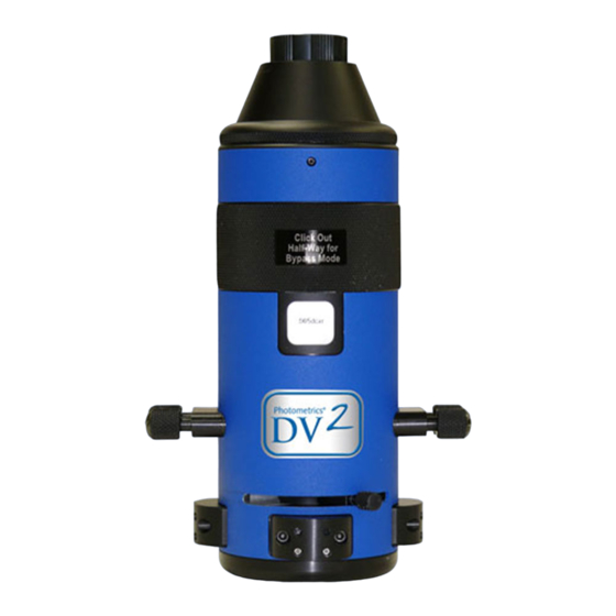
DV2
Alignment Procedure
™
This document provides a straightforward, step-by-step outline of the alignment procedure for the
Photometrics
DV2 imaging system. If use of the procedure does not produce alignment within the
®
specifications listed for the DV2 system, please contact us at support@photomet.com.
NOTE: PLEASE READ THE ENTIRE PROCEDURE BEFORE
YOU BEGIN ALIGNMENT OF THE DV2.
Install DV2 on Microscope
1. Attach your camera to the DV2 by screwing the female C-mount on the camera to the male
C-mount on the DV2.
2. Remove the C-mount adapter from the video port of your microscope (Figure 1a) and screw the
adapter into the female C-mount on the DV2 (Figure 1b). The DV2 is designed to work with a
1x C-mount adapter without additional lenses. Use of any other C-mount adapters may alter
imaging performance.
(a)
Figure 1. (a) Remove the C-mount adapter from the camera port of the upright microscope.
(b) Attach the C-mount adapter to the DV2.
3. Attach the "camera/DV2/adapter" combination to the microscope by sliding the C-mount
adapter into the video port of the microscope (Figure 2). Position the DV2 so that its logo faces
either towards the ceiling (for side-port microscopes) or towards you (for top-port or bottom-
port use).
58-500-002 Rev B0
Be careful not to overtighten.
(b)
H I G H - P E R F O R M A N C E E M C C D & C C D C A M E R A S F O R L I F E S C I E N C E S
Alignment Procedure
1
Advertisement

Summary of Contents for Photometrics DV2
- Page 1 NOTE: PLEASE READ THE ENTIRE PROCEDURE BEFORE YOU BEGIN ALIGNMENT OF THE DV2. Install DV2 on Microscope 1. Attach your camera to the DV2 by screwing the female C-mount on the camera to the male C-mount on the DV2. Be careful not to overtighten.
- Page 2 5. Make sure the objective is of the PlanApo variety and that there is no phase ring in the objective. 6. Pull the DV2 filter slide halfway out of the tube, i.e., Bypass Mode (Figure 3). 7. The slider lever should stay in Dual-View Mode (Figure 4).
- Page 3 The white or grey area indicates where light is reaching the camera. This white or grey area is an image of the internal DV2 aperture mask. If the area is white, you may be saturating the camera. Please lower the intensity of the brightfield light until the white area becomes a light grey color.
- Page 4 Alignment Procedure ™ Figure 5. (a, b) Images of the DV2 aperture show that the aperture and camera are not aligned with each other. (c) Aperture edges are vertical when the camera is properly aligned to the DV2. 3. The DV2 is supplied with a C-mount adapter that can rotate independently from the rest of the DV2 body.
- Page 5 Alignment Procedure ™ 8. The DV2 is equipped with four CCD aperture blades, one for each side of the chip. The position of this mask is adjusted with the lower set of 0.05" hex screws on each of the four aperture adjustment panels on the DV2.
- Page 6 Step 3: Right/left positioning of images With the completion of Step 2, the internal aperture of the DV2 has been centered in respect to the camera attached on the back. Step 3 ensures that the right/left position of the images on the camera is correct.
- Page 7 4. Make sure the slider lever is in Dual-View Mode (Figure 4). 5. The DV2 filter holder should be in Bypass Mode (halfway out of the tube, Figure 3). 6. Adjust the microscope focus until the image of the grid is in focus on the computer screen.
- Page 8 The completion of Step 4 oriented the grid properly in respect to the microscope and DV2. Now you are ready to position the images correctly in the up/down position. Before beginning this step, it is important to realize that the images will rotate as they are moved up and down.
- Page 9 Alignment Procedure ™ Figure 14a Figure 14b As the images are moved up, their tops rotate inward, towards each other. Figure 14c Images in ideal up/down position As the images are moved down, their bottoms rotate inward, towards Figure 14d each other.
- Page 10 Mouse pointer reference Figure 16. Images of the grid (DV2 Mode) with an edge of the grid in the field of view. The left image is too high in respect to the reference point. 3. Look only at the image on the left.
- Page 11 Mouse pointer reference Figure 16. Images of the grid (DV2 Mode) with an edge of the grid in the field of view. The left image is now coincident with the reference point. 4. Pull the DV2 filter holder halfway out of the DV2 tube (Bypass Mode) so that you once again see only one image of the grid in the center of the image field (Figure 18).
- Page 12 Mouse pointer reference Figure 20. Images of the grid (DV2 Mode) with an edge of the grid in the field of view. The right image is now coincident with the reference point. Step 6: Fine alignment using software feedback: To align the two images to each other to within a few pixels, you will need to use your software’s alignment module.
- Page 13 Alignment Procedure ™ www.photomet.com info@photomet.com USA +1.520.889.9933 Asia Pacific +65.6841.2094 France +33.1.60.86.03.65 Germany +49.89.660.779.3 Japan +81.3.5639.2731 UK +44.1628.890858 58-500-002 Rev B0...
Need help?
Do you have a question about the DV2 and is the answer not in the manual?
Questions and answers