Table of Contents
Advertisement
Advertisement
Table of Contents

Related Manuals for KINSHOFER NOXProp+

Summary of Contents for KINSHOFER NOXProp+
- Page 1 Installation instructions for the control system NOXProp+ February 2020 [EN]...
- Page 2 83607 Holzkirchen Germany Tel.: +49 (0)8021 - 88 99 0 Fax: +49 (0)8021 - 88 99 37 Email: info@kinshofer.com www.kinshofer.com * The original operating instructions, for which the manufacturer assumes responsibility, are the German-language version. All other versions are translations of the original operating instructions.
-
Page 3: Table Of Contents
Table of Contents Important notes ......................6 1.1. Safety instructions ....................... 7 1.1.1. Fundamental risks ............................ 7 1.2. Statutory safety and accident prevention ..............7 1.2.1. Safety directives for quick exchange systems ..................7 1.2.2. Safety guidelines for controls ........................8 1.3. - Page 4 3.4. Electronic devices ..................... 19 Installation and initial operation ................20 4.1. Assembly and installation ..................20 4.1.1. Electrical and hydraulic connections ...................... 20 4.1.2. Sandwich NOX ............................21 4.1.3. Fit jib cable on excavator arm ........................ 22 4.1.4. Assembly in the driver's cab ........................23 4.1.5.
- Page 5 4.4. I/O status ........................66 4.5. Fault messages ......................67 Appendix ........................70 5.1. Electrical connections ....................70 5.1.1. Terminal ..............................70 5.1.2. Cab module ............................71 5.1.3. NOX module ............................74 5.1.4. Jib cable ..............................76 5.1.5. CAN distributor ............................76 5.1.6.
-
Page 6: Important Notes
Important notes Important notes These instructions apply to the attachment pictured on the title page, which was developed and produced with the utmost dedication. Technical information, assembly and maintenance instructions are provided in this manual. Service manual and spare parts list A service manual is available upon request for carrying out repairs on premium line products. -
Page 7: Safety Instructions
Important notes 1.1. Safety instructions These operating instructions are valid only in conjunction with the „Safety instructions“ booklet, which is delivered with every attachment. If the booklet is missing, it can be requested free of charge for all EU languages using article number 194079333. -
Page 8: Safety Guidelines For Controls
The responsibility for tasks must be stipulated and made known by the operating company. These installation instructions are aimed at the following target groups: • Kinshofer service personnel • Certified partner's workshop personnel Service personnel Personnel who carry out the installation and commissioning work. -
Page 9: Type Plates
Important notes 1.5. Type plates The type plate is always located on the rear side of the attachment. Terminal Product name Kinshofer article number Vemcon serial number Software version Hardware version Cab input module Kinshofer product name Kinshofer article number... - Page 10 Important notes Cab output module Kinshofer product name Kinshofer article number Vemcon product name Vemcon article number Software article number Version NOX module Kinshofer product name Kinshofer article number Vemcon product name Vemcon article number Software article number Version NOXProp+...
-
Page 11: Storage
Use the original packaging for any return shipping. Dispose of the packaging in accordance with regional regulations. 1.8. Service link • Spare parts • Technical support • Returns http://www.kinshofer.com/eng/index.php/en/service Service link 1.9. Abbreviations Abbreviation Meaning Auxiliary button Button for auxiliary functions Controller Area Network Serial Fieldbus system with linear structure... -
Page 12: Product Information
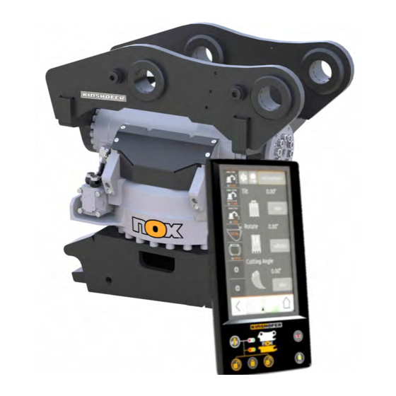
Product information Product information 2.1. Proper intended use The product is used to control the tiltrotators as well as the X-Lock and conventional hydraulic quick-couplers on excavators. The product is intended for use in a commercial environment. 2.2. Product overview Plug connection Boom cable 15 m Terminal... -
Page 13: Terminal
Product information 2.3. Terminal The tiltrotator, the quick coupler and the valves are controlled with the terminal. The terminal shows the system status and fault messages and generates acoustic warning signals. Settings as well as the calibration of the joysticks are implemented at the terminal. -
Page 14: Joystick Grips
Product information 2.4. Joystick grips All of the NOX tiltrotator actions are controlled via two joystick grips. The joystick grips are mounted instead of the original joysticks. The following buttons and rollers are assigned as standard and are connected to the cab module. -
Page 15: Cab Module
Product information 2.6. Cab module The cab module reads the signals from the joysticks and controls the pressure reduction valve. NOXProp+ 01.04.2020... -
Page 16: Nox Module
Product information 2.7. NOX module The NOX module controls the valves in the tiltrotator and reads inputs. Tilt L Tilt, left Tilt R Tilt, right Extra1A Extra function 1, direction A Extra1B Extra function 1, direction B Rotation sensor Absolute sensor Ext B Code Rot CW Rotate clockwise... -
Page 17: Cable Loom
Product information 2.8. Cable loom NOX cable Jib cable Joystick cable Rear roller Front roller Pressure reduction valve cable Pressure reduction valve 1A Analogue pressure reducer valve Pressure reduction valve 1B NOXProp+ 01.04.2020... -
Page 18: Restrictions
Product information CAN distributor Ground Voltage supply Cab module Terminal Jib cable Analogue pressure reducer valve cable Analogue pressure reducer valve 2.9. Restrictions WARNING Danger of injury and property damage due to misuse. Improper use of the attachment can lead to hazardous situations, operational interruptions and to the voiding of the warranty. -
Page 19: Technical Information
Technical Information Technical Information 3.1. General technical data Terminal Cab module Description Value Operating voltage 9 to 35 V Short-circuit tolerance All inputs and outputs protected from operating voltage and GND (except for USB) Ambient temperature -35 to 80 °C -30 to 80 °C Relative humidity Max. -
Page 20: Installation And Initial Operation
Installation and initial operation Installation and initial operation 4.1. Assembly and installation 4.1.1. Electrical and hydraulic connections Hydraulic diagram Cab module Pressure reduction valve Joystick grips Terminal NOXProp+ 01.04.2020... -
Page 21: Sandwich Nox
Installation and initial operation Terminal CAN, excavator control system Ethernet CAN, analogue IN 4.1.2. Sandwich NOX Sandwich NOX means that there is a quick coupler on the excavator and on the tiltrotator. The CAN bus will be connected automatically via the electrical coupling (1/2“, ¾“, V-90) when coupled. -
Page 22: Fit Jib Cable On Excavator Arm
Installation and initial operation 4.1.3. Fit jib cable on excavator arm The jib cable leads from the cab module in the driver's cab along the excavator arm to the vicinity of the tiltrotator where is it connected with the NOX cable. 1. -
Page 23: Assembly In The Driver's Cab
Installation and initial operation 4.1.4. Assembly in the driver's cab Overview Terminal Joystick grips Jib cable Ground Voltage supply Cab module Pressure reduction valve Installing the joystick Material required (included in the delivery): grips • Thread adapter • Clamping ring with counter nut •... - Page 24 Installation and initial operation 1. Remove the original joystick. 2. Screw the thread adapter together with the clamping ring and the counter nut onto the joystick base. In doing so, set the height such that the ergonomics are optimised for the operator. 3.
- Page 25 Installation and initial operation 5. Turn the rubber gaiter to the left and pull it over the joystick grip. 6. Clamp the rubber gaiter in place with the spring clip. 7. Wind the cable around the joystick as a strain relief and fasten with a cable tie or similar.
- Page 26 Installation and initial operation Connecting joystick As standard, the joysticks are delivered each with 2 rollers front and rear (R1 and grips R3) and 7 buttons (S3 – S9). The buttons S6 and S9 as well as the rollers R1 and R3 are connected at the input of the cab module.
- Page 27 Installation and initial operation Connecting the main distributor Ground Ignition Terminal Jib cable 1. Connect the black cable (1) to the cab module and with the ground. 2. Connect the red cable (2) to the ignition via the fuse. Mounting the terminal 1.
-
Page 28: Connecting The Pressure Reduction Valve
Installation and initial operation 4. Fasten the terminal to the RAM Mount base plate with the connecting arm. In doing so, tighten the wingnuts on the connecting arm. 5. Plug in the cab module terminal plug. 4.1.5. Connecting the pressure reduction valve 4.1.5.1. -
Page 29: 4.1.5.2. Connect The Pressure Reduction Valve With Pilot Valve
Installation and initial operation Analogue outputs Stran Function Analogue Out A Analogue Out B 4.1.5.2. Connect the pressure reduction valve with pilot valve If a pilot valve is installed, the pressure reduction valve is connected as follows: 1. Plug in the pressure reduction valve cable at the cab module and connect with the pressure reduction valve. - Page 30 Installation and initial operation 1. Check which is the pressure line and which is the tank line of the circuit. 2. Disconnect the original line between the footpedal and the main control block. 3. Connect the footpedal with the Ped connection on the pressure reduction valve.
-
Page 31: Connecting The Excavator Control System
Installation and initial operation 3. Seal the Ped connection with the screw plug. 4. Connect the pressure reduction valve with the main control block via the A connection. 5. Connect the pressure reduction valve with the oil tank via the T connection. 6. - Page 32 Installation and initial operation Female Function Shield Power Supply 9 to 36 V (do not connect) CAN1_H CAN1_L The manufacturers of the excavator control systems take the supply for the devices directly from the battery. For this reason, pin 2 should not be connected as this would result in unnecessary current draw when the ignition is switched off.
-
Page 33: Commissioning
Installation and initial operation 4.2. Commissioning WARNING Serious injuries through unexpected actions by the quick-coupler and the tiltrotator! • Make sure that the engine of the excavator is switched off. • Ensure that there are no persons in the vicinity of the tiltrotator. •... -
Page 34: Functions Of The Buttons And Rollers
Installation and initial operation 4.2.2. Functions of the buttons and rollers The functions of the buttons and rollers are shown with symbols that are shown to the users on the terminal display: In doing so, the functions that are associated with the functional scope of the tiltrotator, are individually assigned to each user profile. - Page 35 Installation and initial operation Breaker Travel selector switch Parking brake Differential lock Unlock swing axle Swing axle locked Tilt main arm to the right Tilt main arm to the left Lock swivel linkage Unlock/lock tool Vibration damping Mute radio Functions of the cabin module Rotation Toggle between rotate / extra 1 Toggle between rotate / extra 2...
-
Page 36: Starting Commissioning Mode
Installation and initial operation aPWM 1 Analogue pulse width modulation, output 1 aPWM 1A Analogue pulse width modulation, output 1, direction A aPWM 1B Analogue pulse width modulation, output 1, direction B aPWM 2 Analogue pulse width modulation, output 2 aPWM 2A Analogue pulse width modulation, output 2, direction A aPWM 2B... - Page 37 Installation and initial operation 3. Tap the Settings button. 4. Select the Info menu item in the main menu. 5. Tap the X of NOX. NOXProp+ 01.04.2020...
- Page 38 Installation and initial operation 6. Tap the Enable extended functions button. 7. Tap the arrow button to call up the main menu again. Further menu items appear in the main menu: NOXProp+ 01.04.2020...
-
Page 39: Set Joystick Assignment
Installation and initial operation 4.2.4. Set joystick assignment The functions of the buttons that are directly connected to the excavator control system can be set in the Joystick assignment menu. 1. Select the Joystick assignment menu item in the main menu. 2. -
Page 40: Adding User Profiles
Installation and initial operation The button will be assigned the selected function: 4.2.5. Adding user profiles Up to four user profiles can be added in the User profiles menu. The functions of the buttons and rollers can be individually set for each user profile linked to the cab module. - Page 41 Installation and initial operation 3. Enter the user name. 4. Activate the user profile. Calibrating joysticks The joysticks must be calibrated completely during the initial installation. If the rollers need to be replaced due to damage, then the rollers need to be calibrated again, see "Setting rollers".
- Page 42 Installation and initial operation Setting joystick In order to set the functions of the buttons and rollers for the user profile, proceed assignment as follows: 1. Tap the Left joy. or Right joy. button. 2. In order to change the function of a button or roller, tap the corresponding symbol.
- Page 43 Describes the play around the centre position, where the function is not activated. Sensitivity Adjusts the maximum output signal. The output signal may be reduced for training purposes. Kinshofer recommends 100% for normal operation. Invert Changes the direction of the roller.
- Page 44 Installation and initial operation 3. Increase the Non-linearity value, to 50% for example. 4. To adjust the Dead zone value, tilt the roller a little in both directions. If the function activates quickly, increase the value, and if the function activates too late, lower the value.
-
Page 45: Selecting The Tiltrotator
Installation and initial operation 4.2.6. Selecting the tiltrotator All available NOX models are stored with standard values in the NOX models menu. The model used can be selected and individually configured. 1. Select the NOX model menu item in the main menu. 2. -
Page 46: Carrying Out Automatic Calibration
Installation and initial operation Adjust the duty cycle of The duty cycles of the PWM signals are pre-configured for each NOX model, but the PWM signals these may be adjusted as required. Minimal duty cycle: The valve coils require a minimum electrical potential to open. If the minimum is set too low, a long dead time will result. - Page 47 Installation and initial operation 2. Select the Auto. calib. menu item in the main menu. 3. Select the tiltrotator used. 4. Tap the Start auto. calibration button and follow the instructions on the terminal. 5. If the tiltrotator does not have a rotation sensor, set the valve currents in the NOX model and Feeder menus manually.
-
Page 48: Setting The Pressure Reduction Valve (Feeder)
Installation and initial operation 4.2.8. Setting the pressure reduction valve (Feeder) The different functions of the tiltrotators require different quantities of oil. The pressure reduction valve controls the oil quantity required for the individual functions. The feeder values of the pressure reduction valve for the individual functions must be carefully selected as they have a major influence on the behaviour and the performance of the tiltrotators. - Page 49 Installation and initial operation 1. Select the Feeder menu item in the main menu. 2. Select single or double feeder type. 3. Set the minimum and maximum currents with the slide controllers. 4. In order to simulate a roller, select Joy. emulation. The values can be set under Joy.
- Page 50 Installation and initial operation Setting joystick A roller can be simulated with the joystick emulation. The signals used for the emulation roller are dependent on the excavator type. The following signals can be set: Signal Explanation 0 to 5 V Adapt voltage range.
-
Page 51: 4.2.8.2. Set The Feeder Values
Installation and initial operation 3. Set the values with the slide controllers. 4. To invert the direction of the signal, tap Invert. If the tiltrotator does not move, this is a possible solution. 4.2.8.2. Set the feeder values The feeder values for the various functions must be manually matched to one another if the tiltrotator has no rotation sensor (option). - Page 52 Installation and initial operation 1. Select the NOX model menu item in the main menu. 2. Tap the Rotate button. 3. Set the minimum values for clockwise rotation min CW and counter-clockwise rotation min CCW to 3000 mA. Correct feeder values The feeder values for the various functions are set and corrected with the help of a characteristic curve.
- Page 53 Installation and initial operation 1. Select the Feeder menu item in the main menu. 2. Tap the Feeder correct button. 3. Mark the lowest point in the chart. NOXProp+ 01.04.2020...
- Page 54 Installation and initial operation 4. Increase the oil flow to 3%. 5. Increase the valve current until the tiltrotator moves slightly. 6. Tap the arrow button to call up the main menu. NOXProp+ 01.04.2020...
- Page 55 Installation and initial operation 7. Select the NOX model menu item in the main menu. 8. Tap the Rotate button and set the values to the previous values. 9. Alternatively, set the values to the factory settings Set standard values. 10.
- Page 56 Installation and initial operation 12. Tap the Feeder correct button. 13. Move all other points so that a characteristic curve with a positive gradient is created. 14. Mark the 4th point. 15. Move the roller with the rotate function until it reaches the limit stop. NOXProp+ 01.04.2020...
- Page 57 Installation and initial operation 16. Change the oil flow so that the cross-hairs lie on the 4th point. 17. Increase the valve current until the hydraulic pump on the excavator can be heard to start pumping: Too high results in increased fuel consumption. Too low results in the speed of the tiltrotator being too low.
- Page 58 Installation and initial operation Set direct activation If the tiltrotator is uncoupled, the hammer line can be activated directly if a double pressure reducer valve is installed. This is necessary if an additional hydraulic attachment should be operated without NOX. If the direct activation is active, the control system switches to direct activation automatically once the tiltrotator is uncoupled.
-
Page 59: Adjust Ramps
Installation and initial operation 2. Tap the Functions button and select Direct Mode. 3. Set the Direct mode A and Direct mode B feeder values. 4.2.9. Adjust ramps The activation times for the pressure reduction valve and NOX at the start and end of the movement can be separately set for each function in the Ramps menu. -
Page 60: Setting The Quick Coupler
Installation and initial operation 3. Tap the Up button and set the values for the pressure reduction valve (feeder) and NOX for the start of movement with the slide controllers. In doing so, ensure that the pressure reduction valve is activated before the NOX starts. - Page 61 Installation and initial operation Sensors If sensors are installed, the function must be activated. The LEDs on the terminal and the display on the main screen show the status of the interlocking. Re-locking time The flap will be automatically locked again after this time. The function is available only with quick couplers with two-stage locking.
-
Page 62: Add Tool Profiles
Installation and initial operation 4.2.11. Add tool profiles The tiltrotator requires different amounts of oil for different tools or tasks with the excavator. For example, a compactor requires more oil than a grab. These settings can be saved in a total of 10 profiles. 1. -
Page 63: Optional Functions
Installation and initial operation 6. Select the desired tool profile. 7. Set the Tilt, Rotate, Extra 1 and Extra 2 functions for the selected tool: Function Setting Explanation Tilt Speed Reduces the speed for the tilt function. Rotation Speed Reduces the speed for the rotating function. Extra 1 / Extra 2 Invert Change the direction of the roller extra function 1 or extra function 2. -
Page 64: Functional Checks
1 valve block, suitable for the excavator • 1 cable loom The function must be enabled. Enabling functions 1. Contact Kinshofer by email or using the service telephone number and quoting the machine ID. The enabling code will be issued to you. 4.3. Functional checks All functions must be tested once again at the conclusion of the commissioning: •... - Page 65 Installation and initial operation Unlocking the NOX 1. Press both unlock buttons on the terminal simultaneously and hold for 2 quick coupler seconds. 2. If no automatic feeder time has been set, press the button for the quick-coupler on the joystick too. Locking the NOX quick 1.
-
Page 66: I/O Status
Installation and initial operation Locking the top quick 1. Press the locking button on the terminal. coupler 2. If no automatic feeder time has been set, press the button for the quick-coupler on the joystick too. 3. Carry out a pressure test in order to ensure that the quick coupler is properly locked. -
Page 67: Fault Messages
Installation and initial operation 4.5. Fault messages The central controller carries out internal and external checks. If a fault is detected, a red exclamation mark appears on the left edge of the display. 1. Tap the red exclamation mark. A list with all activated faults appears. 2. - Page 68 Installation and initial operation Tiltrotator Moisture in plugs or electrical couplings. 1. Check wiring from the cab to the connected but the tiltrotator. terminal shows "No 2. Measure voltages at the NOX module. tiltrotator" The following voltages should be present (pin 4 negative): •...
- Page 69 Installation and initial operation Rotation angle 1. Check the wiring to the rotary encoder works unreliably in the NOX module. (missing steps, 2. Check the wiring to the absolute sensor jumps) in the NOX module. 3. Adjust the distance between the rotation sensor and the wheel.
-
Page 70: Appendix
Appendix Appendix 5.1. Electrical connections 5.1.1. Terminal Key DTM04-12 PC Function Power Supply 9 to 36 V CAN2_H CAN2_L CAN3_H CAN3_L CAN4_H CAN4_L Analogue IN 1.1 Analogue IN 1.2 Analogue IN 2.1 Analogue IN 2.2 M12 D-code Ethernet Female Function Ethernet TD+ Ethernet RD+ Ethernet TD-... -
Page 71: Cab Module
Appendix M12 A-code CAN Female Function Shield Power Supply 9 to 36 V CAN1_H CAN1_L 5.1.2. Cab module Input Key DTM04-12 PA Left joystick Right joystick Front button Front roller Rear button Rear roller NOXProp+ 01.04.2020... - Page 72 Appendix Left joystick Assignment Function 5 V Out max. 200 mA Supply for roller Analogue IN 6.1 / Quad. 3A Armrest open Analogue IN 7.1 Roller A, front Analogue IN 8.1 Roller A, rear Analogue IN 9.1 Front button Analogue IN 10.1 3rd.
- Page 73 Appendix Key DTM04-12 PD Output Left output Right output Left output Assignment Function 5 V Out max. 200 mA – Analogue IN 6.1 / Quad. 3A QC main sensor A Analogue Out 3.1 Analogue pressure reducer valve 2A Analogue Out 3.2 Analogue pressure reducer valve 2B Out High 4.1 Excavator QC+...
-
Page 74: Nox Module
Appendix 5.1.3. NOX module Tilt L* Tilt R* Extra1A* Extra1B* Rotation sensor Absolute sensor Ext B Code Rot CW* Rot CCW* Extra2A* Extra2B* QC Knuckle* *Valve connector Valve connector connections Function NOXProp+ 01.04.2020... - Page 75 Appendix CAN connections Function V_Bat CAN_H CAN_L Rotation sensor connections Function V_Bat fused Absolute sensor connections Function V_Bat fused – Signal Ext B Code connections Function +5 V Analogue IN 6.1 / Quad. 3A V_Bat fused NOOA+ NOOB+ NOOB- NOOA- Analogue IN 8.2 / Quad.
-
Page 76: Jib Cable
Appendix 5.1.4. Jib cable Jib cable CAN connections Function V_Bat CAN_H CAN_L 5.1.5. CAN distributor CAN distributor Ground Voltage supply Cab module DTM plug connection, terminal CAN, jib cable CAN connections Function V_Bat CAN_H CAN_L NOXProp+ 01.04.2020... -
Page 77: Joystick Cable
Appendix DTM connections Function Description V_Bat Supply – CAN2_H – CAN2_L CAN_H CAN3_H CAN_L CAN3_L – CAN4_H – CAN4_L – A IN 1.1 – A IN 1.2 – A IN 2.1 – A IN 2.2 5.1.6. Joystick cable Joystick cable Rear roller Front roller MICRO-Fit... -
Page 78: Pressure Reduction Valve Cable
Appendix 5.1.7. Pressure reduction valve cable Pressure reduction valve cable Pressure reduction valve 1A Analogue pressure reducer valve Pressure reduction valve 1B Function Description Right AOM plug – +5 V 5 V Out max. 200 mA – – Analogue IN 1.1 / Quad. 1A AF1:1 –... - Page 79 Appendix Function Description Left AOM plug – +5 V 5 V Out max. 200 mA – – Analogue IN 6.1 / Quad. 3A AF2:1 – Analogue Out 3.1 AF2:2 – Analogue Out 3.2 AUX1A:1 – Out High 4.1 AUX1B:1 – Out High 4.2 AUX1B:2 –...
-
Page 80: Claims, Warranty And Liability
Claims, warranty and liability Claims, warranty and liability 6.1. Complaint In the event of a complaint, contact the contractual partner or manufacturer. After agreement with the manufacturer, return damaged parts in their original packaging. Enclose a completed returns form with the return. Include the serial number of the attachment (see chapter 1). -
Page 81: Installation Declaration
Installation declaration Installation declaration In the sense of the EC machinery directive 2006/42/EC, annex II 1B The manufacturer: Kinshofer GmbH Raiffeisenstrasse 12 D - 83607 Holzkirchen hereby declares that each product of the range • Tiltrotator control system NOXPROP is an incomplete machine in the sense of the EC machinery directive and complies with the basic requirements of this directive. -
Page 82: Locations
Locations Locations NOXProp+ 01.04.2020...
Need help?
Do you have a question about the NOXProp+ and is the answer not in the manual?
Questions and answers