Alesis Vortex Wireless 2 Service Manual
Hide thumbs
Also See for Vortex Wireless 2:
- User manual (16 pages) ,
- User manual (21 pages) ,
- User manual
Advertisement
Quick Links
Advertisement

Related Manuals for Alesis Vortex Wireless 2


Summary of Contents for Alesis Vortex Wireless 2
- Page 1 ELECTRONIC KEYBOARD LQVL SERVICE MANUAL...
-
Page 2: Table Of Contents
Contents Features............................3 General Exploded Drawing and List....................5 Circuit Boards..........................6 Parts List............................15 PCB Boards..........................22 Diagnosis............................28 Frequently Asked Questions......................35 Spare Parts List..........................36... -
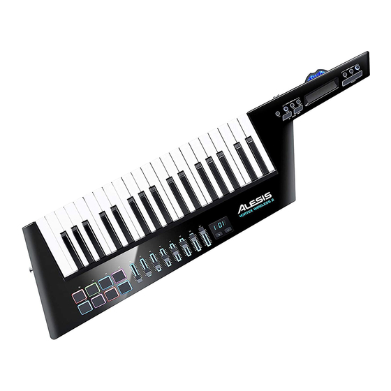
Page 3: Features
Vortex Wireless 2 to download the included editor software. Power Switch: Use this three-position switch to power Vortex Wireless 2 on or off. Set this to Batt to power it on using 4 AA batteries (install these beforehand). Set this to USB to power it on using USB power from a connected computer. - Page 4 Features 13. Ribbon Banks (1–3): Use these buttons to select any of the three banks of the ribbon controller. In each bank, the ribbon controller can send a different type of MIDI message, enabling you to send up to three different messages per preset. You can set the range (the values corresponding to its minimum and maximum positions) and type of MIDI message in the software editor.
-
Page 6: Circuit Boards
Circuit Boards Main Board Schematic-01... - Page 7 Circuit Boards Main Board Schematic-02 BUTTON_DATA_B BUTTON_DATA_C BUTTON_DATA_D BUTTON_DATA_E BUTTON_DATA_F 4148 Preset+ 4148 Preset- SLIDER00 SLIDER01 SLIDER02 SLIDER03 47uF/16V SLIDER04 SLIDER05 SLIDER06 SLIDER07 AFTERTOUCH...
- Page 8 Circuit Boards Main Board Schematic-03 3 DOT FD_LED1A FD_LED1B FD_LED2A FD_LED2B FD_LED3A FD_LED3B FD_LED4A FD_LED4B FD_LED5A FD_LED5B FD_LED6A FD_LED6B FD_LED7A FD_LED7B FD_LED8A FD_LED8B PRESET+ PERSET-...
- Page 9 Circuit Boards Main Board Schematic-04 33k 1% 5.6k 1% 22U/10V 22uF/16V 220K 220K 220K LED_PWR0 LED_PWR1 LED_PWR2...
- Page 10 Circuit Boards IO Board Schematic BAT+ TC623-30uH PWR_BAT COMMON PWR_VBS PWR_VBS VDD_3.3V 1N4001 BAT- PWR_VBUS 1000uf/16V SS24 MIDI_OUT Connect to Switch Board TC623-30uH VBUS To MB J2 DLW21HN121SQ2 POWER & USB MIDI_OUT VDD_3.3V VDD_3.3V MIDI_OUT MS-CON-MIDI_JACK 4.7K MIDI_OUT 8550 100U/16V 5V/0.15PF 5V/0.15PF 5V/0.15PF...
- Page 11 Circuit Boards Function Board Schematic-1 Left button Board Schematic Connect to Button Board2 J1 LED_PWR0 LED_PWR1 LED_PWR2 From Button Board2 J1 BUTTON_DATA_E BUTTON_DATA_F LED_DATA_G LED_DATA_H LED_PWR2 LED_PWR1 LED_PWR0 BUTTON_DATA_E 4148 Sustain 4148 RB_mode1 BUTTON_DATA_F LED_DATA_G 4148 RB_mode2 LED_DATA_H 4148 RB_mode3 Function Board Schematic-1 Right button Board Schematic LED_PWR0...
- Page 12 Circuit Boards Accelerometer Board Schematic VDD_3.3V Accelerometer Module AVDD_3.3V RESERVED DVDD 10U/25V AVDD DGND I2C1_SDA AGND GMA301_INT I2C1_SCL GMA302 10U/25V From Main Board J4 VDD_3.3V AVDD_3.3V GMA301_INT I2C1_SDA I2C1_SCL Function Board Schematic-1 PAD Board Schematic LED_PWR1 LED_PWR0 AVDD_3.3V U5-A 3 QA LED_DATA2 4 QB 5 QC...
- Page 13 Circuit Boards Receiver Board Schematic VDD_3.3V SI24R1 M CU VDD_3.3V ANT1 VBAT VDDA PC13_TAMPER_RTC 33nf PC14_OSC32_IN 22K 1% PC15_OSC32_OUT BOOT0 OSC_IN SI24R1_CE SPI2_NSS OSC_OUT SPI2_SCK SPI2_MOSI RESET MOSI 3.9nH MISO VDD_PA RESET SPI2_MISO PA0_WKUP 2.7nH PA15 Si24R1 SI24R1_IRQ SWCLK PA14 2.2nF 4.7pF SWDIO...
- Page 14 Circuit Boards Keybed Board Schematic B A W 56 D 33 B A W 56 D 34 B A W 56 B A W 56 D 35 B A W 56 B A W 56 D 36 B A W 56 B A W 56 B A W 56 D 37...
- Page 15 Level Part Number Description Specification Usage Remark Unpacking part of the electronic 1020109200 LQVL 1.00000 SET keyboard 1020405430 Top cabinet ASSY LQVL 1.00000 SET HIPS injection black spray oil black silkscreen 201030725 Top cabinet 1.00000 PCS White and Pantone Process Cyan C PU ++++ 201010215 Top cabinet...
-
Page 16: Parts List
Parts List 7.07000 PCS C27 C107-C112 +++++ 603010225 CAP CERAMIC SMD 22uf/10V +20% -20% 0603 SMD X5R C28-30 C43-47 C50-51 C53 C56-59 C62 C64-68 C74-C76 +++++ 603010004 CAP CERAMIC SMD 100pf/50V +5% -5% 0603(NP0) SMD 32.32000 PCS C78-81 C97 C103-C105 C98 C99 C117-121 C124-126 +++++ 603010157... - Page 17 Parts List 1.01000 PCS R20 +++++ 602010021 Resistor SMD 100K ohm(1/16w)+1%-1% 0603 1.00000 PCS XT1 ++++ 610070002 Crystal DIP 49S 6MHz (HC-49S) DIP ++++ 603020007 CAP ELECT SMD 47uf/6.3V +/-20% 4*5MM 1.00000 PCS C85 1.00000 PCS C25 ++++ 603020042 CAP ELECT SMD UT1A221M0605VG 220uf/10V 6.3*5.4 1019903220 Pad Board ASSY...
- Page 18 Parts List 9091-0121-K MK46_FSR_Film 621030064 Film Switch 1.00000 PCS Sensor_V02_160108 631020017 Black Velvet paper 66*30*0.3mm viscosity 2.00000 PCS 18PIN L=50mm PH1.0mm two side with 5mm 628060211 FFC Cable 1.00000 PCS stiffening plate conductor with 3mm L=450mm UL2468 24AWG Both sides with Blue and White Flat Cable with 628072056 8pin/2.54 anti-drop cathode plug Cathode plug in...
- Page 19 Parts List Black ground T=0.8mm 43.9*35.4mm 3m double 642010589 LENS 1.00000 PCS sides adhesive tape 22.00000 PCS for PCB 301110010 screw BB 2.6*6BB black Zn plating “+” Dual teeth PWB EVA black 16*16*6mm with 3M Double-sided 631040493 EVA PAD 1.00000 PCS adhesive strips 631020154 Black Velveteen...
- Page 20 Parts List 204010021 Black key ABS injection black N/A 3.00000 PCS ++++ 298010001 Plastic 0.05562 Kg ++++ 298050010 Color seed M5735C 70%ABS250+30%AS 0.5kg 1.19360 g 205010115 Single white key ABS White N/A 1.00000 PCS ++++ 298010001 Plastic 0.01648 Kg ++++ 298050016 Color seed A61 YS-87527-SM (The ratio 8%)
- Page 21 ITF-14 bar code Black word on white 90*42mm 0.66660 PCS 640000414 Safety and warranty manual Five language 100g/60g 5.5*8.5inch ALESIS 1.00000 PCS Size: 120*120 mm the material is 400g of copper 640000304 Ableton paper card plate the bottom of the light to half light Black 1.00000 PCS...
-
Page 22: Pcb Boards
PCB Boards Main Board-1 Main Board-2... - Page 23 PCB Boards I O Board PAD Board...
- Page 24 PCB Boards Right Button Board 19 20 19 20 17 18 17 18 15 16 15 16 13 14 13 14 11 12 11 12 9 10 Left Button Board...
- Page 25 PCB Boards Keybed Board...
- Page 26 PCB Boards Transmitter Board Receiver Board...
- Page 27 PCB Boards Accelerometer Board...
-
Page 28: Diagnosis
2. Hold down the lowest “C”+ “C#”+ “D”+ “E”, then push the Power Supply switch to battery. 3. Run the software MIDI-OX on computer, then select the two “VORTEX WIRELESS 2” in the MIDI Inputs box. Select “Microsoft GS Wavetable Synth” in the MIDI Outputs box. As shown in the picture... - Page 29 Diagnosis Operating Instructions System self-testing consists of 5 parts: test 1 ~ test 5. Use the following control buttons to switch between the tests. Hold down the [SUSTAIN] button, then press [OCT+] to switch to the next test item. Hold down the [SUSTAIN] button, then press [OCT-] to go back to the previous test item. Test 1: Version Number When it enters system self-testing, it will automatically check the version number.
- Page 30 Diagnosis In Test 3, the display will show the button number which you need to press. For example, when the display shows “F01”, it indicates you need to press the first button on the right side, the [SUSTAIN] button. If there is a button LED, the related LED will light up as well. Check the buttons strictly in the sequence as marked in the picture below.
- Page 31 Diagnosis Note: Once starting the fkey test (after pressing the fkey “SUSTAIN”), you cannot switch to another test until all the fkeys are passed in this test. If the display reports an error by showing “Err”, the test will stop and wait until the problem is fixed.
- Page 32 Diagnosis After all the keys are passed, the display will show “PAS”. Now, hold down the [SUSTAIN] button, then press [OCT+] to switch to Test 5 (ADC). Notes: If the display reports an error by showing “Err” (either because of pressing the wrong key or because the playing strength is not correct), the test will stop and wait until the problem is fixed.
- Page 33 Diagnosis Detailed ADC controllers: Display Controller Pitch bend wheel Ribbon Volume slider SL1- SL8 Slider 1- Slider 8 Pd1 - Pd8 Pad 1- Pad 8 After touch Accelerator Pitch bend: Push the wheel all the way to the right, the display will show “127”, then release the wheel, the display shows “064”.
- Page 34 Diagnosis After touch: Press hard any key on the keyboard until the value reaches “127”, release your hand, the value will reach 0 and it will switch to the next controller “Acc”. (The display will temporarily show “Acc”, then show the accelerator value.) Accelerator: Stand the keyboard up vertically and the value will reach “127”, then put the keyboard flat on a table, the value will reach 0 and the display will show “PAS”.
-
Page 35: Frequently Asked Questions
Frequently Asked Questions Problem Possible Cause and Solution Even with no power supply problems, Check the hardware. the instrument still could not start up. LEDS -- Not lighting Check the AC jack, have it been connected reliably. A poor contact would cause unsuccessful power supply Button problems Run “test 3 Function Buttons”... -
Page 36: Spare Parts List
Spare Parts List PCB Parts Parts Number Parts Name Parts Specification Quantity Picture/Number in Exploded Diagram Price(USD) 1010114840 Main Board ASSY LQVL 1 set 1019903220 Pad Board ASSY LQVL 1 set 101990326 Left Button Board ASSY LQVL 1 set Right Button Board 1019903240 LQVL 1 set... - Page 37 Spare Parts List 20pin L=280mm UL2651 28AWG Both with Computer flat cable with 6280720640 2*10Pin/2.54mm cathode plug 1pcs cathode plug in both sides with butterfly style buckle Plug in different sides Wireless Transmitter 1019903200 LQVL 1 set Board ASSY 101990316 Wheel LED Board ASSY LQVL 1 set...
- Page 38 Spare Parts List Fader Light Guide LQVL PC material White plastic bag 218010084 8pcs DL-2334 toner: YS1801A 1012401080 Pitch wheel ASSY LQVL 1set ABS injection Pantone 299010129 Fader cap 8pcs process black C N/A Silica gel 30°Milk White 25% 629990394 Drum pad opaque top side with black 1pcs...
- Page 39 Spare Parts List 205010115 Single white key ABS White N/A 1pcs 205010113 White key(3key group) ABS White N/A 3pcs 205010114 White key(4key group) ABS White N/A 3pcs 530*13*2.0mm white single 631030310 Bottom limit felt side with glue the hardness of 1pcs 60 degrees 520*6*2.5mm black felt single...
- Page 40 English bright white PET white 641011153 Label word on black size:81*40mm 1pcs 4-R1 Multilanguage 140*216mm 639002562 Manual 1pcs 100g/60g “ALESIS” 300g pink gray+A3 strengthen(120g) 647000790 Gift box 1pcs dieline:940*305*107mm 4C+UV L=2000mm±50 PVC Black magnet ring one side USB “A” 6280800120...
Need help?
Do you have a question about the Vortex Wireless 2 and is the answer not in the manual?
Questions and answers