Table of Contents
Advertisement
Quick Links
Advertisement
Table of Contents

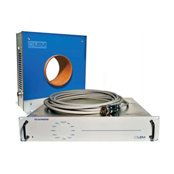
Summary of Contents for LEM ITZ FLEX ULTRASTAB
- Page 1 ITZ FLEX ULTRASTAB USER GUIDE 140528/2 Page 1 of 32...
-
Page 2: Table Of Contents
13.4 Connecting to an external burden resistor (current output) ........... 30 13.5 Connecting the ITZ FLEX ULTRASTAB to a DMM or high impedance amplifier (voltage output) 30 Theory of operation ........................31 Basic principle of ITZ FLEX ULTRASTAB current transducers ........... 31 14.1... -
Page 3: List Of Figures
05.01.2012 Creation of user manual Version: 0 06.02.2013 Replaced Manual title by user guide Version: 1 title (page 1) + Replaced LEM Danfisik by LEM Switzerland + Added picture page 11 Modified some pictures 28.05.2014 Updated completely according to the... -
Page 4: Introduction
Please read this user guide carefully before use. It contains information on how to set up and use the ITZ FLEX ULTRASTAB and how to build an ultrahigh precision system. In case of unanswered questions do not hesitate to contact either LEM Switzerland S.A. - Page 5 WARRANTY STATEMENT 140528/2 Page 5 of 32...
-
Page 6: Receiving And Unpacking
IN CASE OF DAMAGE If the equipment is damaged in any way, a claim should be filed with the shipping agent, and a full report of the damage should be forwarded to LEM Switzerland S.A. or our local representative immediately upon receiving. -
Page 7: General Specifications For Rack Electronics
GENERAL SPECIFICATIONS FOR RACK ELECTRONICS Electrical Data – MAINS INPUT Mains Input 100-240 V AC, 50/60 Hz IEC-type inlet socket Fuses 2.5 AT / 240 V AC Internal fuses, user- replaceable Electrical data – ANALOG OUTPUT PORT Full-scale output current ±1 A (±... -
Page 8: Compliance With Regulations
IEC/EN 61010-1 Electromagnetic Compatibility: Emission: IEC/EN 61326-1:2006 FCC 47 CFR Part 15 Immunity: IEC/EN 61326-1:2006 A technical file is kept available at: LEM Switzerland S.A. Chemin des Aulx 8 P.O. Box 35 1228 PLAN-LES-OUATES Geneva, Switzerland 140528/2 Page 8 of 32... -
Page 9: Usage Precautions And Recommendations
WARNING: The unit has no user replaceable fuses. In the event that fuses need replacement please consult your local LEM Sales representative. Please include Type and Serial no. with all communication with LEM Switzerland or the local representative. 140528/2 Page 9 of 32... -
Page 10: Precautions For Use
Precautions for use Due to the nature of the zero-flux based transducer principle it is necessary to take the following precautions: CAUTION: Do not subject the system to primary current without mains power applied. CAUTION: Do not operate the system with a disconnected secondary when the system is subject to primary current. -
Page 11: Quick Start
Quick start System overview Figure 1: System overview for Current Output Figure 2: System overview for Voltage Output 140528/2 Page 11 of 32... -
Page 12: Setting Up
Setting up To quickly get your new ITZ FLEX ULTRASTAB system operational, follow the instructions given below. 1. Connect the transducer head to the unit using the supplied transducer head cable and mount the programming plug in the connector on the transducer head if your system has the programming feature –... - Page 13 CAUTION: Since the ITZ system has no mains switch the unit will be powered immediately by inserting the mains cord. 4. The ITZ FLEX ULTRASTAB will now measure the current running through the transducer head. On the front plate the status of the unit can be monitored using the status LED panel.
-
Page 14: Introduction
Introduction Main features The ITZ FLEX ULTRASTAB is a high precision current measuring device based on the Flux-gate principle. It can measure current in both the DC and AC domain. The instrument can be configured in a variety of ways to suit the user’s demands. -
Page 15: Custom Transducer Heads
Custom transducer heads For current measurement of 10 kA and beyond certain customizing may be required. Your local LEM SA Sales representative will be able to assist you with custom requirements for conversion ratio, programmability options etc. Voltage output module In addition to the different transducer heads a system can also be equipped with a VOM (Voltage Output Module). - Page 16 Example: A system with an ITZ 2000-50 PR transducer head programmed to 1500 A will produce 1 A when the primary current is 1500 A. The current conversion ratio of the system is then: 1500 1500 When a system is equipped with a VOM, the output current will be converted to a voltage.
-
Page 17: Front
Front Figure 3: Front panel of electronics rack On the front of the ITZ FLEX ULTRASTAB there is an LED indicator panel: POWER: This LED is lit (Blue) when the unit is on. ACTIVE: This LED is lit (Yellow) when the transducer output is active, with I higher than approximately 1% of nominal full-scale output. -
Page 18: Rear
Rear Figure 4: Back panel of electronic rack All connections on the ITZ FLEX ULTRASTAB are located on the rear of the unit. IEC power inlet: This connector accepts a standard IEC power cord. IMPORTANT: The power inlet also serves as mains switch. -
Page 19: Transducer Head
Ventilation exit The main heat sink has an airflow exit centered on the back panel. Inlet holes are on the side panel of the chassis. CAUTION: Do not block the airflow to/from the unit. Transducer head The transducer head is connected to the electronics rack using a dedicated cable with a multi-pin bayonet-style connector. -
Page 20: Installation
Installation Mounting requirements for the electronics unit The ITZ FLEX ULTRASTAB can be mounted in either a rack based system or as a stand-alone unit using the supplied rubber feet. CAUTION: The unit must be mounted horizontally. To ensure proper cooling, keep ventilated ides on side and back panel free. -
Page 21: Grounding The Transducer Head
2 mounting screws before mounting the head. Installation 1. Establish the ground connection (see section 5.3). 2. Mount the provided connection cable between the ITZ FLEX ULTRASTAB electronics and transducer head. 3. Connect the Analog Output Cable as described in section 13.4 and 13.5. -
Page 22: Offset Adjustment
Offset adjustment The ITZ FLEX ULTRASTAB should occasionally have a current offset adjustment made to ensure the highest accuracy. All ITZ FLEX ULTRASTAB are offset adjusted with the accompanying transducer head prior to shipment from the factory. In case the ITZ FLEX... -
Page 23: I/0-Ports
When using the ITZ FLEX ULTRASTAB in current out mode (no VOM installed) only pin 1, 2, 3 and 9, 10, 11 should be used. • Pin 9, 10, 11: Is the current output from the ITZ FLEX ULTRASTAB. • Pin 1, 2, 3: Current return path. -
Page 24: Status/Interlock Connector
Status/Interlock connector All signals on the Status/Interlock port are optically isolated, Photo couplers type, floating Collector and Emitter. Four signals are present on the port, each having two dedicated floating pins in the SUBD9 Male connector: . Collector (C) . Emitter (E) Depending on how each signal is wired, It can be “Active Low”... - Page 25 In the Diagram A Active Low Output, the output signal V switches to GND when the corresponding LED is ON. In the Diagram B Active High Output, the output signal V switches to +U when the corresponding LED is ON. When the output signal V is switched to GND, its value is lower than 0.2 V.
-
Page 26: Absolute Maximum Ratings
In sweep mode, the output current signal will be a slope between ± 1 A, ± 2 A or ± 3 A depending on the transducer head. Thermal protection The ITZ FLEX ULTRASTAB series has thermal shutdown circuitry that protects the electronics from damage. The thermal protection circuitry disables the measuring circuit when the rack electronics temperature reaches approximately 65 °C and allows the transducer to... - Page 27 The secondary current is tracked until the primary AC peak exceeds this trip level. Then, the rack electronics shut down the measuring circuit and wait until the primary AC peak becomes lower than the set trip level. - High frequency range: 1.6 Hz .. 1.6 KHz (over current fast) In this case, the over current trip level is set to 160 % of I PN DC The secondary current is tracked until the primary AC peak exceeds this trip level.
-
Page 28: Transducer Head Connector
5.3. 3. Connect the power cord to the mains inlet 4. The ITZ FLEX ULTRASTAB will now run through its power up sequence. After a few second the unit is ready and the status of the unit can be seen on the front panel LEDs 5. -
Page 29: 13.3 Connecting Directly To A Current Measuring Device
13.3 Connecting directly to a current measuring device Connecting the ITZ FLEX ULTRASTAB directly to a current measuring device like a DMM or a power analyser, can easily be done from the current output port with two standard 4 mm banana plugs. Take care that both terminals are floating relative to ground. -
Page 30: Connecting To An External Burden Resistor (Current Output)
13.4 Connecting to an external burden resistor (current output) If an external burden resistor is to be connected to the ITZ FLEX ULTRASTAB the connection shown below should be used. Figure 7: Wiring schematics to external burden resistor In addition to the standard current output cable of 1.5 m length a 5 m long current output cable is also available. -
Page 31: Theory Of Operation
Theory of operation 14.1 Basic principle of ITZ FLEX ULTRASTAB current transducers The ITZ FLEX ULTRASTAB current transducers are delivered in a series covering galvanic isolated measurements of currents from DC to 500 kHz ranging from 40 A to 24 kA. -
Page 32: Maintenance
6. The system is a calibrated entity that should be recalibrated every 2 years to ensure the calibration level of the system. To get your ITZ FLEX ULTRASTAB recalibrated we recommend shipping it to LEM Switzerland S.A.
Need help?
Do you have a question about the ITZ FLEX ULTRASTAB and is the answer not in the manual?
Questions and answers