
Summary of Contents for Hellermann Tyton T609
- Page 1 DIGIT AL CLAMP METER T609 200A CAT II 300V *Only illustrative image. INSTRUCTIONS MANUAL...
-
Page 2: Table Of Contents
INDEX 1) OVERVIEW ..................02 2) SAFETY ..................... 03 3) ACCESSORIES ................04 4) PRODUCT DESCRIPTION .............. 05 5) DISPLAY SYMBOLS ................. 06 6) OPERATION ..................07 A. Current Measurement ..............07 B. Special Functions ..............08 7) MAINTENANCE ................. 09 A. -
Page 3: Overview
1) OVERVIEW This operating manual covers information on safety and cautions. Please read the relevant information carefully and observe all the Warnings and Notes strictly. Warning To avoid electric shock or personal injury, read the Safety Informa- tion and the following instructions carefully before using the Meter. •... -
Page 4: Safety
2) SAFETY This manual contains information and warnings that must be followed to safe operation of the instrument and to keep the instrument in safe operation conditions. If the instrument is used in a different way than the specified by the manufacturer, the protection provided by the instrument may be impaired. -
Page 5: Accessories
TERMS IN THIS MANUAL WARNING identifies conditions and practices that may result in serious injuries or even death. CAUTION identifies conditions and practices that may cause damage or instrument malfunction. WARNING To reduce the risk of fire or electrical shock do not expose this instrument to rain or high humidity. -
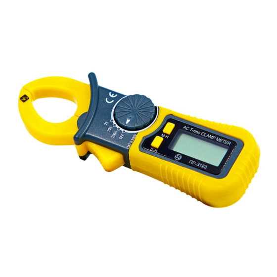
Page 6: Product Description
4) PRODUCT DESCRIPTION 1) Transformer clamp jaw to pick-up AC current. 2) Hand / Finger barrier to indicate the limits of safe access to the jaw during current measurements. 3) Jaw trigger to open it. 4) Rotary switch to turn the power ON / OFF and range selection. 5) The buttons used to operate special functions &... -
Page 7: Display Symbols
5) DISPLAY SYMBOLS Number Symbol Meaning Indicator for low battery level. AC (Alternating Current). Indicator for Data Hold mode. Indicator for Maximum Hold mode. Amperes. Current Unit. -
Page 8: Operation
6) OPERATION A. Current Measurement - AC CAT II 300V Set the rotary switch to the proper range, ACA (alternating current) for T609 NOTE For non-invasive current measurement, press the jaw trigger and clamp the jaw around only one single conductor of a circuit for load current measurement. -
Page 9: Special Functions
B. Special Functions D-H Button The Data Hold function freezes the current reading to later visualization. Press D-H button for a moment to enter in the Data Hold mode. Press D- H button again to return to normal measurements. M-H Button The Max Hold function freezes the highest reading to later visualization. -
Page 10: Maintenance
7) MAINTENANCE CAUTION! Do not attempt to repair or service your meter unless you are quali- fied to do so and have the relevant calibration, performance test, and service information. To avoid electrical shock or damage to the meter, do not get water inside the case. A. -
Page 11: Specifications
8) SPECIFICATIONS A. General Specifications Display: LCD 3 1/2 digits (2000 counts) Jaw Opening & Conductor Diameter: 19mm maximum Sampling Rate: 3 times per second nominal Polarity : Automatic Low Battery: Range Selection: Manual T emperature Coefficient: 0.1 x (specified accuracy) / °C (< 18°C or > 28°C) Operation Environment: 0°C to 40°C, <... - Page 12 AC Current Overload Range Resolution Accuracy Protection 0.001A 0.05A~2A ± (2.0%+8D) 50~60Hz 0.5A~20A ± (2.0%+5D) 50~60Hz 0.01A 0.5A~20A ± (3.0%+10D) 45~400Hz 200A RMS 5A~200A ± (2.0%+5D) 50~60Hz 200A 0.1A 5A~200A ± (3.0%+10D) 45~400Hz Note: Frequency Response: 50Hz ~ 60Hz DC Current Range Resolution Accuracy...
-
Page 13: Warranty
WARRANTY SERIAL Nº MODELS: T609 1- The warranty period is 12 (twelve) months and begins on the date of purchase. 2- It will be repaired free of charge in following cases: A) Manufacturing defects or damages occurred under normal use of instrument within the warranty period.