Table of Contents
Advertisement
Quick Links
Advertisement
Table of Contents

Related Manuals for RSS magLEAD 12gC

Summary of Contents for RSS magLEAD 12gC
- Page 1 12gC Instruction for Use Version 2 May 2022 Doc. No.: P30001PE0101-07...
-
Page 2: Table Of Contents
Index 1. Information for the User ................3 2. Information for Safe Usage ..............5 3. Specifications ..................11 3.1. Intended Use ......................11 3.2. Features ......................... 11 3.3. Performance ......................11 3.4. Size, Weight, and Power Requirements............... 11 3.5. Storage Conditions .................... - Page 3 8. Basic Operation ..................35 8.1. magLEAD 12gC Operation Panel ................ 35 8.2. Startup and Shutdown Procedure ................ 35 8.2.1. Startup ......................... 35 8.2.2. Shutdown ......................36 8.3. Protocol Run Procedure ..................36 9. Manual Operation .................. 38 9.1. Manual Screen ....................... 38 9.1.1.
-
Page 4: Information For The User
1.Information for the User Congratulations on purchasing the magLEAD 12gC instrument, which features Precision ® System Science’s worldwide patented Magtration technology utilizing magnetic particles. This Instructions for Use provides information necessary for the safe and effective use of the instrument. Please read this manual thoroughly to familiarize yourself with the device and its settings before you use it. - Page 5 Reagents (Not included) Code Name E1300 MagDEA Dx SV IC card (Not included) Code Name I7712 MagDEA Dx SV 200 12gC I7812 MagDEA Dx SV 400 12gC For other RUO products, please see the PSS homepage. Please notice to the manufacturer and the competent authority of the Member State in which the user and/or the patient is established, in case where any serious incident has occurred in relation to the device.
-
Page 6: Information For Safe Usage
Indicates a medical device that is intended to be used as an in vitro diagnostic medical device. magLEAD 12gC is not considered as a medical device (IVD) in the United States of America, and it is not registered with the FDA. - Page 7 CE mark for Europe Regulation (EU) 2017/746 (IVD Directive) This instrument has been tested and complies with the following standards: IEC61010-1 Amd.1 Ed3: 2016, “Safety requirements for electrical equipment for measurement, control and Laboratory use ‐ Part 1: General requirements” IEC61010-2-101: 2018, “Safety requirements for electrical equipment for measurement, control, and laboratory use ‐...
- Page 8 ⚫ Do not use kits other than the MagDEA Dx reagent kits. ⚫ The magLEAD 12gC CANNOT be used as an accessory for any of following diagnostic applications: 1) Determination of: ◆ blood groups: ABO system, rhesus (C, c, D, E, e), anti-Kell, anti-Duffy or anti-Kidd ◆...
- Page 9 Warning The following precautionary instructions are included to ensure safe operation of the magLEAD 12gC instrument. Please always keep this manual near the instrument or operator. Failure to comply with the instructions in this manual may pose dangerous risk to the user and will void the manufacturer’s warranty.
- Page 10 Caution Installation • Avoid installing the instrument in the locations indicated below. Prohibited This may cause instrument damage or malfunction. acts -Locations exposed to direct sunshine -Locations with high vibrations, humidity, or dust -Locations with strong electric or magnetic fields -Locations where liquid or oil could splash onto the instrument -Locations with flammable gas, corrosive gas, or high heat sources.
- Page 11 About the Warranty Period • 12 months after installation, regardless of the instrument usage. • This warranty excludes problems that occur due to inadequate storage, inadequate usage or operation, or repair, modification, or maintenance of the instrument by people who are not authorized by PSS, even within the warranty period. About Disposal •...
-
Page 12: Specifications
The instrument is intended to be used only in combination with the MagDEA Dx reagent kits for magLEAD 12gC instrument only for the applications described in the product’s instructions for use. The system is intended for use by professional users, such as technicians and physicians trained in molecular biological techniques and the operation of the magLEAD 12gC. -
Page 13: Storage Conditions
➢ Designed to last 5 years or more (4 runs/day, 250 day/year) with proper maintenance. Environmental Requirements Wall More than 200 mm More More Back than 200 than 200 Wall Wall magLEAD 12gC Front Doc. No.: P30001PE0101-07... -
Page 14: About The Caution Labels Inside The Instrument
Caution • Place the instrument on a horizontal surface that can support the instrument weight. • Place the instrument on a horizontal surface. • Do not place the instrument in locations exposed to direct sunlight or vibrations. • When operating the instrument in a cold chamber or cold room, keep the instrument power on to avoid condensation. -
Page 15: Caution Label For Crushing Of Hands
3.8.2. Caution label for crushing of hands Place attached:Magtration® Unit Caution • The area where this label is attached can potentially pinch your hand or fingers in the driving mechanism of the open/close operation. Take care not to be pinched. 3.8.3. -
Page 16: Caution Label For Uv Lamp
Place attached:Top of the instrument cover CAUTION UV emitted from this product. IEC62471 Risk Group 2 Caution • The magLEAD 12gC contains a UV lamp. Avoid looking directly at the UV light. Do not expose your skin to UV light. Doc. No.: P30001PE0101-07... -
Page 17: System Components
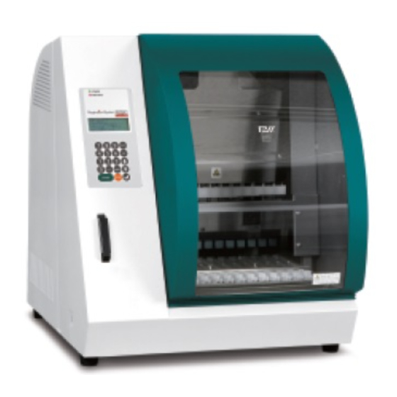
4.System Components 4.1. Front View *1 Power Status LED (green) *2 Alarm Status LED (red) Display Operation Panel IC Card Inlet Door *1: Green LED: Lit when powered on *2: Red LED: Blinks if an error occurred Doc. No.: P30001PE0101-07... -
Page 18: Side And Rear View
4.2. Side and Rear View The power switch is located on the left side of the instrument. The fuse box and connectors are located on the back of the instrument. Power Switch Fuse box RS232C Connector for PC Power Cable Connector Connector Handheld... -
Page 19: Internal Components
4.3.Internal Components ® The Magtration unit and stage unit are located inside the instrument. UV lamp Unit Syringe Unit Magnets Reagent Cartridges Tip Sets Sample Tubes (magLEAD Tip and Sheath set) Elution Tubes ® Magtration Unit ➢ Syringe Unit:Twelve nozzles for simultaneous processing of up to 12 samples with accurate and rapid aspiration and dispensing. -
Page 20: Installation
5.Installation 5.1. Setup procedure 1. Remove the instrument from the shipping crate. Warning • The instrument will be installed by field service personnel authorized by PSS. Contact us if you need to move the instrument. 2. Remove the protective films attached to the instrument. 3. - Page 21 5. Remove the bubble wrap, Y-axis fixing bracket, and silica gel bag. 6. Connect the power cable and the handheld barcode reader that came with the instrument. Connect the power cable to the wall outlet. Power Cable Connector for PC RS232C Connector for Handheld Barcode Reader...
- Page 22 7. Confirm that the power switch is turned off. Following the images below, open the inlet cover and insert the IC Card. Make sure that the picture side is on the left and the triangle mark ▽ faces down when inserting the card. After inserting the card, turn on the power using the switch on the left side of the unit.
-
Page 23: Configuration And Setting Up The Instrument
5.2.Configuration and setting up the instrument 5.2.1.Setting the installation date The first time the magLEAD 12gC is switched on, the installation date must be entered. This date will be recorded in the report file described below. In addition, the instrument uses this installation date for determining when to display the weekly and annual maintenance reminders. -
Page 24: Installing The Pc Software (Optional)
The data communication between the barcode reader and the instrument uses a RS232 interface. 5.3.Installing the PC software (optional) The magLEAD 12gC software “magLEAD Communicator” must be installed on the PC. This software is required for receiving report files from instrument and storing instrument data on the PC hard disk. -
Page 25: Mapping The Com Port (For Users Of "Windows 10 Professional")
5.3.3.Mapping the COM port (For users of “Windows 10 Professional”) ■ Right-click on the Windows button to open the “Device Manager”. NOTE: The way to open the “Device Manager” differs depending on the OS you are using. ■ Open the “Device Manager”. NOTE: The process to open the Device Manager varies according to the operating system version. -
Page 26: Installing The Maglead Communicator
■ Change the dialog field “COM Port Number” to “COM1”. The USB port is now mapped to COM port 1. Always use COM Port 1 when working with the magLEAD 12gC. 5.3.4.Installing the magLEAD Communicator ■ Insert the CD labeled “magLEAD Communicator” into the PC. - Page 27 ■ The magLEAD Communicator is now ready to receive data from the instrument. ■ To check the connectivity between the PC and magLEAD 12gC, follow the test described in Section 9.4.3. Doc. No.: P30001PE0101-07...
-
Page 28: System Components
6.System Components 6.1. Accessories Power Cable Power Cable for 100VAC Power Cable for 240VAC - Silicon Grease, Fuses, and D-Rings Silicon Grease Fuse (3.15A) D-Rings - Reagent Cartridge Rack - Tip/Tube Rack Doc. No.: P30001PE0101-07... - Page 29 - Handheld Barcode Reader (optional) Reference Refer to the user manual for the barcode reader for details. - magLEAD Communicator (PC Software, optional product) Reference Please refer to “Installing the PC software (Chapter 5.3)” for details. Doc. No.: P30001PE0101-07...
-
Page 30: Disposables
6.2. Disposables magLEAD Tip and Sheath set Micro tube・Screw cap Reference Refer to the package insert of the disposables for details. 6.3. Reagents Prefilled Reagent Cartridges Reference Refer to the package insert of the reagent kit for details. Doc. No.: P30001PE0101-07... - Page 31 Caution • Do not reuse any disposables to avoid contamination and/or instrument malfunction. • Do not use disposables or reagents other than those specified to avoid instrument malfunction. • Be sure to wear a mask, goggles, and gloves for your own safety when loading or discarding reagents, disposables, and samples.
-
Page 32: Directions For Use
7.Directions for Use 7.1. Door operation The door moves up to open and down to close. It is held by magnets at both the top and the bottom. When opening or closing the door, be careful not to pinch your hand or fingers and be sure that the door is held in place by the magnets at the top or the bottom. - Page 33 Place the reagent cartridge rack into the rack position on the stage. Reference Be sure that two farthest wells of the cartridge fit into the heating block. Caution • Operating the instrument operation with the Reagent Cartridges or the Reagent Cartridge Rack incorrectly positioned may result in instrument malfunction.
-
Page 34: Inserting Sample Tubes
7.3. Inserting Sample Tubes Place Micro tubes (without caps) containing the samples into the Tip/Tube Rack. 7.4. Inserting magLEAD Tip and Sheath sets magLEAD Tip and Sheath set insert them into the holes of the Tip/Tube Rack. 7.5.Inserting Elution Tubes Place the Micro tubes (for elution) into the Tip/Tube Rack. -
Page 35: Inserting The Tip/Tube Rack
7.6. Inserting the Tip/Tube Rack Place the tip/tube rack into the instrument. Refer to the pictures below for the placement direction of the rack. Please make sure that the tip/tube rack is correctly aligned with the location pins. Back side of the instrument Front side of the instrument... -
Page 36: Basic Operation
8.Basic Operation 8.1. magLEAD 12gC Operation Panel Operation Panel Description Choosing a menu 0~9 7 8 9 Returns to previous menu 4 5 6 START Runs protocol STOP Halts or aborts protocol 1 2 3 (Enter) ENTER: Confirm or enter the next menu 0... -
Page 37: Shutdown
Confirm that the run has been fully completed. Turn the instrument power switch off. 8.3. Protocol Run Procedure After inserting the protocol IC Card and switching on the magLEAD 12gC, follow the steps below to start a protocol. From the MENU Screen, press the “START” key to run a protocol. - Page 38 Discard the used reagent cartridge and plastic consumables according to your local safety regulations. The magLEAD 12gC will automatically generate a report file, and send it to the PC. Note For generating and sending a report to the PC, confirm that the serial port has been set correctly.
-
Page 39: Manual Operation
9.Manual Operation 9.1. Manual Screen Press the “2” key from the MENU Screen to display the Manual Screen. Press the ESC key from the Manual Screen to return to the MENU Screen. DD MM YYYY HH:MM START:Run 1:UV 2:Man 3:Test 4:Setup Key:START,1,2,3,4 Manual Screen MANUAL OPERATION... -
Page 40: Return Tip Screen
MANUAL OPERATION home axis Axis Executing... 9.1.2. Return Tip Screen Press the “2” key from the Manual Screen to display the following screen: MANUAL OPERATION return tip START:Run Key:START,ESC Press “START” to perform the Return Tip operation to return any tips that are attached to the Syringe unit into tip holders. -
Page 41: Resend Screen
If a report file cannot be sent to the PC, it will be temporarily stored on the magLEAD 12gC instrument. Up to 10 report files can be stored. Use the “resend” function to manually transmit the report file(s) to the PC. -
Page 42: Uv Screen
UV lamp as described below. Note UV decontamination helps to reduce possible pathogen contamination of the magLEAD 12gC stage surfaces. The efficiency of inactivation must be determined for each specific organism and depends on the layer thickness and sample type. -
Page 43: Switching Off The Uv Lamp
After entering a valid time, press “START” to switch on the UV lamp. The stage will move slowly back and forth under the UV light. During the UV decontamination run, the following screen is shown: DECONTAMINATION>Run TotalTime:TT min. LeftTime: LL min. Key:STOP “TT”... -
Page 44: Setup Screen
Starting at 50 cycles before the 5000-cycle limit, the instrument will display this screen every time the instrument is switched on. “XXXX” indicates the number of cycles remaining. If this number is “0”, the UV lamp must be replaced. Contact Precision System Science or a distributor for UV lamp replacement. 9.3. -
Page 45: Setting The Serial Port
SETUP: TIME HH:MM Key: Up,Dn,SHIFT,ENT,ESC Press “SHIFT” and the down arrow to move the cursor to the right, from HH (hours) to MM (minutes). Press “SHIFT” and the up arrow to move the cursor to the left, from MM to HH. Press the up arrow or down arrow to increase or decrease the value of the selected field. -
Page 46: Test Screen
9.4.Test Screen Open the Test Screen by pressing the “3” key from the MENU Screen. Press the “ESC” key from the Test Screen to return to the MENU Screen. DD MM YYYY HH:MM START:Run 1:UV 2:Man 3:Test 4:Setup Key:START,1,2,3,4 TEST 1:Axis 2:Temp 3:Serial 4:Version... -
Page 47: Serial Port Test Screen
TEST: TEMPERATURE Temp: ss.s C actual: aa.a C Key:ESC “ss.s” indicates the set temperature, and “aa.a” indicates the current temperature. “r” indicates the result, and displays “O” if the temperature is within a given range or “X” if the temperature is outside the given range. 9.4.3. -
Page 48: Version Screen
Barcode reader Press “2” in the serial port test screen to test the bar code reader. The following screen appears: TEST: Key:ESC Use the barcode reader to read a barcode. When a new barcode is read, the previous barcode will be overwritten. A beep sound indicates a successful barcode scan. -
Page 49: Barcode Reader (Optional)
For generating and sending a report, confirm that the serial port has been properly set up. Refer to section 9.3.3. Up to 10 report files can be stored temporarily on the magLEAD 12gC instrument. When this maximum has been reached, the oldest report file must be deleted before additional reports can be saved. - Page 50 V1.0.0 Current firmware version Installation date Jan 07, 2015 Installation date, which was set the of instr.: first time the magLEAD 12gC was powered on. This date is stored permanently on the magLEAD 12gC. Weekly Jan 14, 2015 When you accept the weekly...
- Page 51 ■ aborted Error code: See section 15 for error codes Sample input Sample input volume in microliters; volume [µl]: depends on the protocol Elution Elution volume in microliters; Volume [µl]: depends on the protocol Channel 1: Information for channel 1 begins here Sample ID: 8730...
-
Page 52: Maglead Communicator (Optional)
12.magLEAD Communicator (optional) magLEAD Communicator is a software program that runs on a PC. The software receives the report file (refer to section 11) and stores it in a folder defined by the user. After the PC has received the report file, you can use and process the file with a LIMS (Laboratory Information Management System) or other programs. - Page 53 PC. Select “File” to exit the graphical user interface. Select “Options” to display the following window showing the magLEAD 12gC serial ports: COM1 should already be selected. You can check the serial settings by checking one of the boxes.
- Page 54 Select “About” in the main window to show the version of the magLEAD Communicator. Click the “Change path” button in the main window to change the folder where the selected report file will be stored. Browse and select the folder in the following window: Doc.
-
Page 55: Maintenance
13.Maintenance Maintenance items to be performed are listed below. Item Frequency Done by Cleaning of stage and racks After every operation User Cleaning of nozzles and piercing unit After every operation User Greasing of D-rings Once every two weeks User Replacement of D-rings Once every half year Field service... -
Page 56: D-Ring Maintenance
Note • Do not use alcohol when cleaning the clear panel on the instrument door. Instead, use water for those parts. • 70% ethanol is a flammable liquid. If you are using 70% ethanol, ensure that there are no flames nearby. 13.2. - Page 57 Wipe off any excess silicon grease from the edges of nozzles and the tip ejector using lint-free paper. Caution • Excess silicon grease can lead to instrument operation problems, such as improper tip removal. Doc. No.: P30001PE0101-07...
-
Page 58: Troubleshooting
14.Troubleshooting 14.1. Error Reported During Protocol Run Error during process Code:XXX LineNo.= ##### Key:ESC to return The above screen will be displayed, to indicate that an error occurred. (Refer to Chapter 15 for Error Code List.) 1. If an error occurs during a protocol run, the above screen will be displayed. The red alarm LED will blink, an audible alarm will sound, and the instrument will stop operating. -
Page 59: Suspending Or Aborting A Protocol Run
Note • If, after taking appropriate actions, the same error occurs again when running the same protocol, contact us for technical support. 14.2. Suspending or Aborting a Protocol Run It is possible to stop a protocol run while the run is in the data reading phase before extraction phase (e.g., sample tube barcode information). - Page 60 3. After aborting a protocol, press “2” to display “Manual” in the display. Press “2” again to return the tips to the tip rack and to return the modules to their home positions. Caution • If the instrument stops while there are tips on the nozzles, follow the steps described above.
-
Page 61: Frequently Reported Problems
14.3. Frequently Reported Problems Problem Possible cause Countermeasures to be taken Back light of AC power cable Check the AC power cable connection. Be sure to the display is not connected use the power cable that was supplied with the is not lit properly. - Page 62 from one lane to the next. Doc. No.: P30001PE0101-07...
-
Page 63: Error Code List
Communication error between the heating block and and wait about 10 seconds the temperature controller, or the card is not a before turning the instrument magLEAD 12gC Card power back on. Communication error between motors and driver board. contact us for assistance. -
Page 64: Revision History
Note • Most of the errors listed above occur as a result of improper positioning of disposables/accessories or from opening the door. Be sure to check these before restarting a protocol run. • If you encounter error codes other than those listed above or if the error could not be solved by the countermeasure described, contact us with the specific error codes. - Page 65 Precision System Science Co., Ltd. 88 Kamihongou, Matsudo-shi, Chiba, 271-0064 Japan TEL:+81-(0)47-303-4800 FAX:+81-(0)47-303-4811 URL:http://www.pss.co.jp E-mail:service@pss.co.jp Precision System Science USA, Inc. 5673 West Las Positas Blvd., Suite 202, Pleasanton, CA 94588, U.S.A. E-mail:contact@pssbio.com Precision System Science Europe GmbH 55122 Mainz, Mombacher Str. 93, Germany E-mail:contact-psse@pss.co.jp Emergo Europe Prinsessegracht 20, 2514 AP The Hague, The Netherlands...
Need help?
Do you have a question about the magLEAD 12gC and is the answer not in the manual?
Questions and answers