
Summary of Contents for SOLID AIR CPL 1400
- Page 1 02-2022 6809530-202012 INSTRUCTIONS FOR CONTRACTORS TYPE: CPL English | subject to modifications...
-
Page 2: Table Of Contents
Hydraulic connection ..........................................23 Electrical connection ..........................................23 6.8.1 General information..........................................23 6.8.2 Power cable cross-section/onsite fuse protection ...............................24 6.8.3 Motor data ..............................................24 6.8.4 Fixing cable ducts for outdoor units ....................................25 SOLID AIR ® INTERNATIONAL • T +31 598 36 12 21 • www.solid-air.com •... - Page 3 9.1.9 Detailed connection for i1 to i3 ......................................52 9.1.10 Detailed connection for i4 to i5 ......................................53 9.1.11 Overview of cables for onsite wiring ....................................54 9.1.12 Temperature sensors performance curve (NTC5k) ...............................55 SOLID AIR ® INTERNATIONAL • T +31 598 36 12 21 •...
-
Page 4: About This Document
Read this document before you begin working on the appliance. >> Follow the instructions in this document. Failure to observe these instructions voids any Solid Air Climate Solutions warranty. 1.1 Scope This document is for the Solid Air CPL comfort compact ventilation unit. -
Page 5: Safety
+40 °C. The use of these units in wet rooms or rooms with explosive atmospheres is not permissible. Handling very dusty or aggressive media is not permissible. Any onsite modification or improper use of the unit is not permissible and Solid Air GmbH accepts no liability for any damage caused as a result. -
Page 6: General Safety Information
Make the operator aware of the following: • Annual inspections and maintenance must be performed by a contractor. • Solid Air recommends concluding an inspection and maintenance contract with a contractor. • Repair work must be performed by a contractor. •... -
Page 7: Standards And Regulations
DIN VDE 0701-0702 ........Inspection after repair, modification of electrical appliances, periodic inspection of electrical appliances • VDI 2050 ............Requirements for technical equipment rooms - Planning and execution SOLID AIR ® INTERNATIONAL • T +31 598 36 12 21 •... -
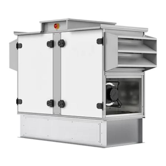
Page 8: Description
15 Outdoor air damper with servomotor (open/close) 7 Adjustable feet 16 Unit isolator 8 PWW aperture 17 Control panel 9 Connectors for DN 50 trap 18 BMK programming unit SOLID AIR ® INTERNATIONAL • T +31 598 36 12 21 • www.solid-air.com • contact@solid-air.nl... -
Page 9: Cpl-Iv Specifications/Dimensions
1 ½ “ 1 ½ “ 1 ½ “ 1 ½ “ Weight (kg) Max. flow rate (m 1400 2400 3300 4700 6100 *Duct connection dimensions SOLID AIR ® INTERNATIONAL • T +31 598 36 12 21 • www.solid-air.com • contact@solid-air.nl... -
Page 10: Cpl-Ih
15 Unit isolator 7 Connectors for DN 50 trap 16 Control panel 8 EC fan, extract air 17 BMK programming unit 9 Exhaust air damper with servomotor (open/close) SOLID AIR ® INTERNATIONAL • T +31 598 36 12 21 • www.solid-air.com •... -
Page 11: Cpl-Ih Specifications/Dimensions
1 ½ “ 1 ½ “ 1 ½ “ 1 ½ “ Weight (kg) Max. flow rate (m 1400 2400 3300 4700 6100 *Duct connection dimensions SOLID AIR ® INTERNATIONAL • T +31 598 36 12 21 • www.solid-air.com • contact@solid-air.nl... -
Page 12: Cpl-A
17 Bypass damper with servomotor (variable speed) 8 Base frame 18 Unit isolator 9 Connectors for DN 50 trap 19 Control panel 10 Boost damper with servomotor (optional) SOLID AIR ® INTERNATIONAL • T +31 598 36 12 21 • www.solid-air.com •... -
Page 13: Cpl-A Specifications/Dimensions
1 ½ “ 1 ½ “ 1 ½ “ 1 ½ “ Weight (kg) Max. flow rate (m 1400 2400 3300 4700 6100 *Duct connection dimensions SOLID AIR ® INTERNATIONAL • T +31 598 36 12 21 • www.solid-air.com • contact@solid-air.nl... -
Page 14: Planning
5.1.1 Minimum clearance between outdoor air intake and exhaust air discharge to prevent an air short circuit Fig. 5.1 CPL-A minimum clearance intake - discharge 1 Outdoor air 2 Exhaust air SOLID AIR ® INTERNATIONAL • T +31 598 36 12 21 •... -
Page 15: Siting The External Unit (Weatherproof)
5.2.1 Connecting the condensate drain pipe and PWW heat exchanger • With weatherproof units sited outdoors, keep the condensate drain and DHW coil free of frost; provide suitable protection if required. SOLID AIR ® INTERNATIONAL • T +31 598 36 12 21 •... -
Page 16: Position Of Operating Side
CPL-A operating side, supply air, left CPL-A operating side, supply air, right Fig. 5.1 Operating side 1 Exhaust air Extract air 2 Outdoor air Supply air SOLID AIR ® INTERNATIONAL • T +31 598 36 12 21 • www.solid-air.com • contact@solid-air.nl... - Page 17 Exhaust air AUL / ODA FOL / EHA 6801059 48/10 6801062 48/10 Extract air Supply air ABL / ETA ZUL / SUP 6801061 48/10 6801060 48/10 SOLID AIR ® INTERNATIONAL • T +31 598 36 12 21 • www.solid-air.com • contact@solid-air.nl...
-
Page 18: Installation
If there is any transport damage or a suspicion of damage, the recipient must indicate this on the consignment note and have it countersigned by the haulier. >> Report all transport damage to Solid Air immediately. >> Dispose of the transport packaging in accordance with local regulations. -
Page 19: Transport
Sort and dispose of metal and plastic parts according to material types and in compliance with local regulations. >> Dispose of electrical and electronic components as electrical waste. SOLID AIR ® INTERNATIONAL • T +31 598 36 12 21 •... -
Page 20: Installing The Outdoor Unit
Insulation if required 2 Roof membrane >> The Solid Air base frame must be insulated and integrated into the roof membrane onsite. >> In the case of elevated positioning (CPL on onsite framework), the CPL must be secured against wind load. -
Page 21: Installing Duct Connections
Dimension B Dimension C Position siphon-connector [mm] (mm) (mm) (mm) CPL-iV-1400 533,5 CPL-iV-2400 711,5 CPL-iV-3300 713,5 CPL-iH-1400 CPL-iH-2400 711,5 CPL-iH-3300 CPL-A-1400 648,5 CPL-A-2400 CPL-A-3300 CPL-A-4700 CPL-A-6100 SOLID AIR ® INTERNATIONAL • T +31 598 36 12 21 • www.solid-air.com • contact@solid-air.nl... - Page 22 Vent longer drain lines to prevent condensate backing up in the line (provide additional vent in trap drain line). Ball trap Trap Fig. 6.6 Trap types >> Fill the trap with water SOLID AIR ® INTERNATIONAL • T +31 598 36 12 21 • www.solid-air.com •...
-
Page 23: Hydraulic Connection
>> Inspect the installation in accordance with the safety requirements of VDE 0701-0702 and VDE 0700 Part 500. >> Comply with the wiring diagram in the Appendix SOLID AIR ® INTERNATIONAL • T +31 598 36 12 21 • www.solid-air.com •... -
Page 24: Power Cable Cross-Section/Onsite Fuse Protection
I We accept no liability for any damage or loss resulting from technical modifications to Solid Air control units. I If control voltage is present or a set speed is saved, the EC fans will restart automatically after power failure. -
Page 25: Fixing Cable Ducts For Outdoor Units
Lay the onsite cable to the control panel in the cable duct/installation tube. 1 M8 threaded holes. Cable duct fitted to threaded holes. 3 Installation tube fitted to threaded holes. SOLID AIR ® INTERNATIONAL • T +31 598 36 12 21 •... -
Page 26: Commissioning
Commissioning and maintenance must be performed by a qualified contractor. >> According to DIN EN 50110-1 (VDE 0105-1), only qualified electricians may carry out the installation and commissioning of the ventilation control unit and connected accessories. SOLID AIR ® INTERNATIONAL • T +31 598 36 12 21 •... -
Page 27: Preparation For Commissioning
Heating circuit pump/cooling circuit pump. • As well as all other system-specific functions. The Solid Air warranty will be void if the function test is not carried out correctly. SOLID AIR ® INTERNATIONAL • T +31 598 36 12 21 •... -
Page 28: Starting The Fans
7.2.3 Electric reheating coil (accessory) >> The electric reheating coil is switched by the temperature controller. >> Minimum air volume. CPL-1400 600 m³/h CPL-2400 1100 m³/h CPL-3300 1500 m³/h SOLID AIR ® INTERNATIONAL • T +31 598 36 12 21 • www.solid-air.com • contact@solid-air.nl... -
Page 29: Countercurrent Plate Heat Exchanger
The doors must be closed to determine the correct flow rate. • Feed the test houses to the outside (e.g. CPL-A through the exhaust air aperture, CPL-iH and CPL-iV through the base). SOLID AIR ® INTERNATIONAL • T +31 598 36 12 21 •... -
Page 30: Measure Effective Pressure
7.3.1 Measure effective pressure Fig. 7.1 Measure effective pressure SOLID AIR ® INTERNATIONAL • T +31 598 36 12 21 • www.solid-air.com • contact@solid-air.nl... -
Page 31: Cpl-1400 Effective Pressure
K value of fan 93. Fig. 7.3 CPL-2400 effective pressure 1 Flow rate Effective pressure Δp Δp (Pa) (m³/h) 1000 1200 1400 1600 1800 2000 2200 2400 SOLID AIR ® INTERNATIONAL • T +31 598 36 12 21 • www.solid-air.com • contact@solid-air.nl... -
Page 32: Cpl-3300 Effective Pressure
K value of fan 140. Fig. 7.5 CPL-4700 effective pressure 1 Flow rate Effective pressure Δp Δp (Pa) 1127 (m³/h) 1900 2300 2700 3100 3500 3900 4300 4700 SOLID AIR ® INTERNATIONAL • T +31 598 36 12 21 • www.solid-air.com • contact@solid-air.nl... -
Page 33: Cpl-6100 Effective Pressure
Further settings for the BMK programming unit can be found in the operating instructions for the WRS-K control unit. • Accessories are installed in accordance with separate instruction manuals, which are provided with the relevant accessories. SOLID AIR ® INTERNATIONAL • T +31 598 36 12 21 •... -
Page 34: Maintenance
Dispose of the dirty air filters in accordance with local regulations. NOTE Operation without filter Contamination or damage of heat exchanger, fan and duct system >> The appliance may only be operated with the designated filters. SOLID AIR ® INTERNATIONAL • T +31 598 36 12 21 • www.solid-air.com •... -
Page 35: Fan Motor Unit
Regularly check the condensate pans for contamination and clean if required. 8.3.9 Trap >> Regularly check the trap for contamination and clean if required. >> Refill the trap with water before returning into use. SOLID AIR ® INTERNATIONAL • T +31 598 36 12 21 • www.solid-air.com •... -
Page 36: Hygiene Cpl Checklist
Check the function of the drain and trap. Clean and repair. Repairs >> Only qualified personnel may remove faults or repair damage. Only replace faulty components with original Solid Air spare parts. >> SOLID AIR ® INTERNATIONAL • T +31 598 36 12 21 •... -
Page 37: Appendix
Frost protection is only guaranteed if mains switch Q1 is not deactivated. • Residual current protective device RCD. Only AC/DC-sensitive fault current safety devices, type B, with 300 mA are permissible. SOLID AIR ® INTERNATIONAL • T +31 598 36 12 21 •... -
Page 38: General Symbols
Symbol for optional components (these components must be selected when purchasing the air conditioning appliance). Symbol for accessories (These components can also be bought from Solid Air later and connected to the air conditioning appliance). Shielded cable. Cable designation: 3 x 1,0 mm²... -
Page 39: Arrangement Of Terminal Strips In Different Versions Of The Unit
Fig. 9.2 CPL-iV Terminal strips with and without control unit CPL-A 1400 to 3300 with and without control unit With control unit Without control unit (XE1/ XE2) Fig. 9.3 CPL-A Terminal strips SOLID AIR ® INTERNATIONAL • T +31 598 36 12 21 • www.solid-air.com • contact@solid-air.nl... -
Page 40: Connections Terminal Strip X1
9.1.3 NS terminal strip X1 N(N) L(L) STB(4) aGHxEL2 L‘(1) L3(K5/5) STB(2) L2(K5/3) L1(K5/1) aGHxEL1 STB‘ aMVxAB aMVxZU SOLID AIR ® INTERNATIONAL • T +31 598 36 12 21 • www.solid-air.com • contact@solid-air.nl... - Page 41 5b) Line present only for the following unit designs: 2400 e.coil + WP, 2400 e.coil + PCW, 2400 without coil, 3300 e.coil + WP, 3300 e.coil + PCW, 3300 without coil. Accessories CPL-1400/CPL-2400, CPL-3300. SOLID AIR ® INTERNATIONAL • T +31 598 36 12 21 •...
-
Page 42: Connections Terminal Strip X2
9.1.4 Connections terminal strip X2 SOLID AIR ® INTERNATIONAL • T +31 598 36 12 21 • www.solid-air.com • contact@solid-air.nl... - Page 43 (installed on the exhaust air side downstream of the HR system). Temperature sensor downstream of HR and upstream of reheating coil sTLvEH Only present/available for the following unit designs: - Systems with Solid Air Clima-Split. sQLxAB Air quality sensor and CO sensor accessories...
-
Page 44: Connections Terminal Strip X3
9.1.5 X3 Connections terminal strip X3 SOLID AIR ® INTERNATIONAL • T +31 598 36 12 21 • www.solid-air.com • contact@solid-air.nl... - Page 45 Floating contacts: 28a: Central fault 28b: Op. message aKOxAM max. 2A@250V Only present/available for the following unit designs: - All with exception of “without coil” designs. SOLID AIR ® INTERNATIONAL • T +31 598 36 12 21 • www.solid-air.com • contact@solid-air.nl...
-
Page 46: Connection Terminal Strip X4
9.1.6 Connection terminal strip X4 SOLID AIR ® INTERNATIONAL • T +31 598 36 12 21 • www.solid-air.com • contact@solid-air.nl... - Page 47 Smoke detector, floating NC contact (onsite) (Note: Insert jumper if component is not present). 4& sKOxRM Only present/available for the following unit designs: - All except “without coil” designs. SOLID AIR ® INTERNATIONAL • T +31 598 36 12 21 • www.solid-air.com •...
-
Page 48: Connection Terminal Strip X6 And X8
9.1.7 Connection terminal strip X6 and X8 SOLID AIR ® INTERNATIONAL • T +31 598 36 12 21 • www.solid-air.com • contact@solid-air.nl... - Page 49 Only present/available for the following unit designs: - Systems with Solid Air. The Solid Air system includes control cables (W10 and W11) in the cable harness. These must be wired into the control panel of the Solid Air system. Please refer to the instructions for information about the connection.
-
Page 50: Connection Terminal Strips Xe1 And Xe2
9.1.8 Connection terminal strips XE1 and XE2 2x0,5mm² (24V) aGKxDV 2x0,5mm² (24V) sKoxBM NO_H 5x1,5mm² COM‘ (variabel) NO_K aGAxWP 4x0,5mm² (24V) SOLID AIR ® INTERNATIONAL • T +31 598 36 12 21 • www.solid-air.com • contact@solid-air.nl... - Page 51 (Note: Insert jumper if component is not present). aGKxDV Only present/available for the following unit designs: - Systems that make use of a direct evaporator for the cooling function. SOLID AIR ® INTERNATIONAL • T +31 598 36 12 21 •...
-
Page 52: Detailed Connection For I1 To I3
9.1.9 Detailed connection for i1 to i3 bBExMK 5x1,0mm² (24V) bBExMF ≥ CAT5 bGLxXX Tx/RX- 3x1,0mm² Tx/RX- (24V) Tx/Rx+ Tx/Rx+ sQLxRA sQLxAB SOLID AIR ® INTERNATIONAL • T +31 598 36 12 21 • www.solid-air.com • contact@solid-air.nl... -
Page 53: Detailed Connection For I4 To I5
9.1.10 Detailed connection for i4 to i5 SOLID AIR ® INTERNATIONAL • T +31 598 36 12 21 • www.solid-air.com • contact@solid-air.nl... -
Page 54: Overview Of Cables For Onsite Wiring
Heat/boiler demand variable Cooling pump 230V Cooling demand variable Heating actuating signal Cooling actuating signal Solid Air Link Pro 24V + shielding Onsite heat pump Onsite heat pump variable Fire alarm system contact Coolunsystem fault message SOLID AIR ® INTERNATIONAL •... -
Page 55: Temperature Sensors Performance Curve (Ntc5K)
3.133 14.750 3.007 14.027 2.887 13.344 2.772 12.697 2.662 12.086 2.558 11.508 2.458 10.961 2.362 10.442 2.271 9.952 2.183 9.487 2.100 9.046 2.020 8.629 1.944 SOLID AIR ® INTERNATIONAL • T +31 598 36 12 21 • www.solid-air.com • contact@solid-air.nl...
Need help?
Do you have a question about the CPL 1400 and is the answer not in the manual?
Questions and answers