
Summary of Contents for ÖVERUM CT
- Page 1 Conventional ploughs CT Conventional ploughs Instruction manual Instruction manual...
-
Page 3: Table Of Contents
This instruction manual deals with Överum conventional ploughs type CT _______________________________________________________________ Contents Page Description of function Identification of plough General safety precautions with safety signs Technical description Checking the tractor prior to ploughing Preparation of plough Mounting the plough onto the tractor... -
Page 4: Description Of Function
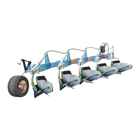
The plough is to be attached to the three-point linkage at the rear of the tractor, with the hydraulic systems connected to the appropriate hydraulic outlets. Description of the plough Accumulator Stone trip Cross-shaft cylinder Disc coulter CT 4980 Mould board shin Mouldboard Share Point... -
Page 5: Identification Of Plough
1.1 Plough identification Type designations Mounted conventional plough CT 2975 – 51080 Stone trip device H = hydraulic F = fixed (shear bolt) Beam height 75 = 75 cm 80 = 80 cm Plough body spacing 9 = 90cm Number of plough body pairs... -
Page 6: General Safety Precautions With Safety Signs
2. GENERAL SAFETY PRECAUTIONS WITH SAFETY SIGNS Safety signs Carefully follow the Operating Instructions and Safety Signs, which warns for risks when personal injuries can occur. Avoid accidents by always following the safety precautions. Read "Operator's Manual". Safety signs with no text are used on these ploughs. -
Page 7: Technical Description
3. TECHNICAL DESCRIPTION 3.1 Checking the tractor prior to ploughing Function of the three-point hitch The design of the three-point linkage is based on the principle that the tractor and the plough should operate as one unit. This function is depending of the settings for the lower links and the top link. These components must therefore be maintained in a condition that enables them to be easily adjusted. -
Page 8: Preparation Of Plough
3.2 Preparation of the plough Check that the quick-couplings on the hydraulic hoses are the same type as the quick-couplings on the tractor. If required, fit the correct quick-couplings, to suit your tractor. Check that the cross-shaft on the plough has the correct category to suit your tractor. Cross shafts are available in different categories: Cat. -
Page 9: Checking The Plough
3.4 Checking the plough • Check the tightness of all bolts and nuts • Grease all lubrication points • Check the tyre pressure 23 x 8,5-12 240 kPa (2,4 bar) • Check that the desired furrow width is correctly, set see page 14. •... -
Page 10: Basic Settings
4. BASIC SETTINGS 4.1 Basic settings, mounted ploughs The basic setting can be started when the desired ploughing depth has been reached and when the tractor wheels are running in a furrow with the same depth. Vertical adjustment Ensure that the plough beams are at right-angle 90º to the ground. If necessary, make adjustments by using the right-hand lower link of the tractor. - Page 11 First furrow width Ensure that the lower links are loose so the plough can move freely. For ploughs equipped with a hydraulic control of the first furrow width, the following applies: Place the hydraulic cylinder in a central position so that it can be adjusted in both directions. Check that the cross-shaft has the correct angle adjustment, see page 14 (Furrow with adjustment ).
-
Page 12: Adjustment Of Skimming Device
4.2 Adjustment / Setting of skimming devices The basic purpose of the skimming devices is to cut off and turn down a corner of the surface layer with crop residues and weeds so that these are well buried. Properly used skimming devices give the best mechanical weed control. - Page 13 Basic setting of skimmers H-ploughs The mounting position of the skimmer bracket on the beam is the same if the plough is equipped with fin coulters or disc coulters. Horizontal measurement (H) = 300 mm Adjust (H) to the correct measurement and make sure that the skimmer stalks are at right angle (90°) towards the beam when the bolts are tightened.
-
Page 14: Stone Trip System
5. STONE TRIP SYSTEMS 5.1 Shear bolt protection type (F) All F type ploughs are protected form damage by means of a shear bolt in each plough leg (part no. 1659 13 99 00). Always ensure that the correct bolt is used for replacement. Share bolt 5.2 Hydraulic, fully automatic type (H) The tripping mechanism consists of a trip cylinder for each plough body. -
Page 15: Adjustment Of Operating Pressure
5.3 Adjustment of operating pressure Connect the filling hose to a single-acting hydraulic outlet on the tractor. Open the valve and adjust the pressure to the required value using the tractor hydraulics, close the valve and repositioning the hose in its original position. NOTE: The plough must be connected to the tractor when adjusting the pressure and when depressurizing the system. -
Page 16: Adjustment Of Working Width
6. ADJUSTMENT OF WORKING WIDTH 6.1 Adjustment of working width mounted CT ploughs The ploughs are assembled as standard on 16” working width. 1. Alternating the beam housing position Each plough body component can swivel around the front bolt in the beam housing D. By placing rear bolt in one of the tree different positions A, B or C you will alter the working (furrow) width. - Page 17 SELECT THE CORRECT FURROW WIDTH The working width should be in relation to the ploughing depth, i.e. max depth = 2/3 of the working width. This gives a sufficient weight to the furrow slices and ploughing will have a good finish. Note! The plough is equipped as standard with shares for 16”...
-
Page 18: Care, Maintenance And Replacement Of Wearing Parts
7 CARE, MAINTENANCE and REPLACEMENT OF WEARING PARTS To ensure the plough a long life and to avoid unnecessary wear, observe the following instructions. 7.1 Greasing of the beam hinge points Position the plough with the bodies approx. 15 cm above the ground. Depressurize the system as described in Adjustment of operating pressure. -
Page 19: Replacement Of Wearing Parts
7.3 Replacement of wearing parts All wearing parts should be replaced in good time in order to protect more vital parts, which will save you money. Always use original spare parts, which will ensure that you get wearing parts with good quality and which fits the plough. -
Page 20: Mouldboards, Tightening Torques
7.4 Parallelism and G-measurement of the mouldboards • Check the working angle of the mouldboard. The normal position is measured on the rear plough body between the extended inside line of the landside, horizontally out against the outermost hole in the mouldboard, see measurement G. -
Page 21: Lubrication Chart
7.5 Lubrication chart 8, 20 Lubrication interval hours * = Use grease that contains Molybdendisulfid... -
Page 22: Extra Equipment
8 EXTRA EQUIPMENT Hydraulic cylinder for adjusting the width of the first furrow Hydraulic adjustment of the first furrow is useful when different soil types and lateral slopes occur in the field, which must be compensated for. Spanish type of cross shaft The plough can also be equipped with a pivoting Spanish cross shaft. -
Page 23: Useful Advice
9. USEFUL ADVICE When you have completed a careful and accurate adjustment of your plough so that it works well and gives a good ploughing result, make a note of the following important measurements. Length of top link ________________________________________________________ Length of right-hand lift rod ________________________________________________________... -
Page 24: Överums Bruk Ab Se-590 96 Överum Telephone: Int+46 493 361
Överums Bruk AB , SE-590 96 Överum Överums Bruk AB , SE-590 96 Överum Telephone: Int+46 493 36100 Telephone: Int+46 493 36100 Telefax: Int+46 493 30800 Telefax: Int+46 493 30800 Web adress http://www.overums-bruk.se E-mail: sales@overums-bruk.se 1656 80 10 41 01.2004...
Need help?
Do you have a question about the CT and is the answer not in the manual?
Questions and answers