Table of Contents
Advertisement
Quick Links
Advertisement
Table of Contents

Related Manuals for Takstar XR26


Summary of Contents for Takstar XR26
- Page 1 使用说明书 User’s Manual XR26 数字调音台 DIGITAL MIXER...
- Page 2 欢 承 惠 购 本 司 产 品 , 感 谢 ! 正 式 使 用 本 产 品 前 , 请 务 必 通 读 此 说 明 书 , 便 使 您 全 面 了 本 设 备 , 并 练...
- Page 3 注 警告! 为了 电、短路、损伤、火灾或其 危险可 导 的人员受伤,请务必 列基 本注 事项。这些注 事项 括但不 于 列情况: 重要 全事项 请勿打开 ● 阅读这些说明,保 这些说明,并 照 ● 本设备 不 有用户可用的任何备 有说明。 件,请勿自行拆卸或进行任何形式的 ● 注 设备上或说明书中的 有 告。 造。 ● 若遇 殊 常情况,必须由经厂 认可 电源/电源线 的专业人士进行检 。...
- Page 4 ● 本设备 其他 设备连 时,请使用 ● 请勿 饮料、 品、火源 在本设备 经制造 认可的连 电缆。 上, 体、固体 和明火损坏设 ● 移动设备 前,请务必 开 有的连 备。 电缆。 操作/ 其他注 事项 ● 在打开保护 壳的情况 ,禁止使用本 ● 请勿长时间在较 的音量 使用耳机, 设备。 否则可 导 听力损 。 ● 在操作使用本设备前,可 通过释...
- Page 5 目 录 1、 欢 -------------------------------------------------------------------- 1 2、 注 -------------------------------------------------------------------- 2-3 3、 目录 -------------------------------------------------------------------- 4 4、 简介 -------------------------------------------------------------------- 5 5、 技术指标 --------------------------------------------------------------- 6 6、 硬件结构 ------------------------------------------------------- 7-10 结构 尺寸 口说明 操作面 说明 7、 软件 制 --------------------------------------------------------------- 11-18 软件更 复 厂设 监听设 输...
- Page 6 简介 此 调音 专业现场 为标 设计,用于 厅、音乐 映厅扩声、 扩 声、现场音频节目录制等应用环 ,其 备 大的功 满足 苛 的专业人士的需求。该 产品在灵活便 、操作简单的同时保证了专业的 音 果, 够帮助经验较 的用户快速获 得 质量的 果。 此 调音 备iOS, Android, Windows, Mac OS 和Linux设备的 平 兼 性,可 通过手机、平 、电脑 连 调音 WIFI/热点...
- Page 7 技术指标 硬件指标 功 指标 2路独 果 通道 26通道输 :12路话筒;4路单声道;2路 输 通道 体声;3路 体声 果 果类型 括:Hall、Room、Plate、Church、 Delay、Chorus、Flanger 12通道输 :主输 L/R;6路BUS输 ;监听 输 通道 输 /L/R;耳机输 阈值Threshold:-80~0dB 减Range:-80~0dB 双轨USB声 录音 口 门 启动时间Attack: 1ms~120ms 双轨U盘录音存储 话筒 -20~+70;线路 -20~+70 释 时间Release: 10ms~4000ms 输...
- Page 8 硬件结构 结构与尺寸...
- Page 9 接口说明 1. 组合输入接口 用于连 话筒或平衡模拟线路输 。XLR 口用来连 话筒,6.35mmTRS 插 口用来连 平衡线路 。这些 口 可 提供+48V 电源。此调音 拥有12个组合输 口。 2. 6.35mm TRS 输入接口 用于连 平衡模拟线路输 。此调音 拥有8个6.35mmTRS输 口,其中 个单声道(Mono)模拟输 口和两对 体声(Stereo)模拟输 口。 3. BUS 母线XLR输出接口 BUS 1 BUS 6 线的平衡输 口, 口采用XLR插口。此调音...
- Page 10 操作面板说明 1. 主编码器旋钮 用于快速调整选中的相应功 (如EQ 、动态 、通道发送 等等)。调音 的绝大多 可调 可在选中后通过主编码 钮调节。 2. 通道编码器旋钮 在通道总览页面中可 调整通道的 和相 ,并通过编码 的 键 换 理的 。在通道编辑页面中可 快速调节EQ 。 3. 通道电平指示灯 用于快速 观地显示通道输 电平状态。当绿灯 起时输 电平>-40dBFS,当黄灯 起时 示输 电平>-20dBFS,当红灯 起时输 电平>0dBFS。 4. 通道按钮 SEL(Select) 钮用于选择该...
- Page 11 5. 通道参数快速调节旋钮 用于在通道编辑界面快速调节常用 。在输 通道的通道编辑界面, 钮由上 分 别调节通道 Gain、EQ 滤波 Low Cut、通道门 值Gate、通道压 值Comp。 6. 屏幕 用于监看调音 的各 工作状态并通过 屏对调音 的 进行设 。 体操作 在 “基本操作” 节详细介绍。 7. 录放音按钮 用于进 U盘的录音 (PLAY/REC)界面,并可 通过 件夹 式浏览 操作U盘 。 8. U盘插口 用于 、录音和软件更...
- Page 12 软件 制 软件更新 您可 本产品的经销 联 , 得 本的软件。 软件升级 :(U盘升级) 升级 件(后缀名为.upk) 贝 U盘的 目录 ; 2. 调音 开机; U盘连 调音 的USB 口; 4. 在Menu-Global 界面 单击Check Update; 5. 操作界面自动 找 显示U盘中 有的可更 的 据 本 息,点击需要升级的 据 件,并 认;...
- Page 13 6. 大约等 3 分钟,调音 重 启动并更 毕。 注 :1. 更 过程中 勿中 电源; 2. 更 前请备 有用户 据 U盘中, 止更 后 据丢失。 恢复出厂设置 调音 提供2 级别的 复设 。一 是还原 有通道的设 ,另一 是清除 有 用户 据、 全 复为 厂设 。 1. 还原 有通道设...
- Page 14 监听设置 本产品 了专业的监听选择 统。调音 监听 线分别 发送给面 上的 MONITORPHONES 耳机监听插口和背 上的MONITOR OUTPUT扬声 监听插口,您可 通过这些插口获得监听 线的 。 您可 通过调音 面 上的SOLO 键 相应通道加 监听 线中,这时,面 右上侧 的主输 电平 变为监听 线电平 ,电平 的CLEAR 钮 变为红色, 示现在有 通道启用SOLO 监听功 。您可 在MENU-MONITOR页面选听SOLO 的通道 子前 (PFL)/ 子后(AFL)的...
- Page 15 数字输出通道设置 本产品的 输 通道可 选择不同的来源 。 您可 在MENU-Digital 页面中 BUS7&8 或MASTER 通道的 作为源 发送给指 输 通道 录音通道(AES/EBU、USB 声 、U盘录音)。...
- Page 16 账户设置 本产品 了账户 码 统,可 止调音 误 碰造成的 事故。本产品 厂默认 码。 若想要设 码,您可 在Menu-Passwrd 页面单击Set Password 钮。 码设 成功 后调音 跳转 码输 页面,输 正 码后点击 认键 可正常使用。若想 除或编 辑 码,您可 在Menu-Passwrd 页面单击Delete Password/Modify 键,输 原 码后 可执行操作。...
- Page 17 网络连接 您可 使用移动 通过调音 的WIFI进行连 ,也可 通过调音 的LAN网口 用网 线连 电脑,实现对调音 的远程操 。连 成后,在移动 或电脑 浏览 中输 调 音 IP地址, 可在网页上加载和使用 制软件。 * WiFi 线连 式: 选择登录调音 的WiFi热点,默认名 为“WIFIMixer”在移动 的浏览 中输 调音 的 线IP地址,默认地址“192.168.2.1”。 * LAN有线连 式: 打开电脑的网络设 ,设 电脑LAN网关为“192.168.1.1”,设 LAN的子网...
- Page 18 进 网络的CONFIG 页面中,您可 在 线连 (Wireless)、有线连 (Wired) 两个子页面分别设 调音 线/有线网络连 设 ,设 成后单击Save 钮 可保存。 线连 (Wireless) 在 线连 页面,您可 设 调音 WIFI网络名 (SSID)和网络 码(Security), 并且可 调整调音 的 道(Channel)。 调音 WIFI 加 式有None/WPA2 两个选项。当选择None 时,热点 码,可 连 。当选择WPA2 时,需要输 设 的调音...
- Page 19 本产品提供了2.412GHz 2.462GHz的11个 线 道供您使用, 据不同的 理域, Wi-Fi 线频谱范围 可选择多个 道,例如 洲(ETSI)为13,北美(FCC)为11。 三 软件可 帮助选择Wi-Fi通道。由于使用调音 时现场的 线网络环 可 常复杂,如 果当前使用的 道 常拥挤, 导 调音 制 迟,此时, 议您选择使用其他 道。 有线连 (Wired) 在有线连 页面,您可 设 调音 的连 式DHCP/Manual, 有线网络连 的IP 地址、子网 码(Netmask)和网关(Gateawy)。 当您选择动态IP 分配(DHCP)时,调音 自动分配IP、子网...
- Page 20 操作 登陆界面 当您设 了 码时,调音 在启动后 首先进 码输 页面,正 输 码后 可正 常使用。 码相关设 详情 4,软件 制-账户设 。 总览界面...
- Page 21 这是调音 首先进 的通道总览页面, 显示了 个通道的总览 息,从上 次为 通道 、Mic通道 供电开关、 相开关、EQ曲线、噪声门曲线、压 曲线、通道发 送量、通道输 电平 、通道ID、MASTER 线发送开关、静音编组、PAN值、 子 减值、 通道名 。 通道 值和通道PAN值可 在总览界面通过通道 钮调整, 通道 钮可 换选择通道 值和通道PAN值间。 MENU 菜单设置界面 MENU 钮后,您 进 菜单设 页面。该页面 括了Global、Monitor、Digital、 Password、Network 子页面,您可 在这些页面 更 或重...
- Page 22 METER电平表界面 当 METER 钮,您 进 电平 界面。该界面左侧显示了IN1-8、IN9-16、ST IN、 BUS 1-8 层通道的输 电平,右侧显示了 线MASTER 的电平。当一个通道 静音( 启用MUTE 功 )时,电平 的红灯 起。 PRESET 预设/快照界面...
- Page 23 PRESET 键,您 进 预设/快照界面。这个界面显示了调音 有的预设设 。 选择左侧预设并 Load 可应用该预设;单击Save 键可 储存调音 当前的设 ;选择 左侧预设并 Delete 可 该预设删除;在插 U 盘的情况 ,可 使用Export 键和 Import 键 预设 件导 和导 U 盘。 Import 键后 进 U 盘储存预设列 ,您可 Load 键 应用U 盘 预设 调音...
- Page 24 COPY 通道复制界面 COPY 键后,您 进 通道复制界面。您可 左侧列 的通道设 复制 右侧 的通道。 先选择左侧列 的通道,右侧列 现 够 受粘贴的通道,在中间的Copy Options 一栏中设 好复制的 后单击COPY 键 可成功复制通道。...
- Page 25 EFX效果器设置页面 钮后,您 进 果 设 页面。 点击RESET 钮可 各个 果 的 复为各自的 荐值;点击EFFECT 钮可 进 果 选择界面,进 可 看见调音 提供的7 果 和 果 用选项( NONE 键)。 本产品拥有两个 果 通道,您可 在 果 设 页面为两个通道选择您 需要的 果 ,并调整 果 。调音 的常用 果 有各...
- Page 26 本产品 响 果 ,分别是HALL大厅 响、ROOM 间 响、PLATE钢 响、 CHURCH教堂 响。 大厅 响:通常 带来 大的 间感,其 频 减 常明显, 减时间通常也是 长的。 间 响:带来的 间感觉更为 观,让人明显感觉 间的存在。 钢 响:较为华丽,其 频 减不明显,不易 现较大的 间感。 教堂 响: 大厅 响类 ,但是 频 减 缓。 本产品开 响Reverb 供调整:...
- Page 27 DENSITY:调整合唱 果的 。合唱 ,结果 厚和 富。 LPF: 通滤波 。通过调节该 架滤波 的 止频 来减 频 量, 于该值的频 过滤/删除。 HPF: 通滤波 频 。削减 频,减 “ ”声和不想要的浑浊。 4.珐 /镶边Flanger 镶边 果 通过调整 迟声的音调,使声音上 摇晃而产生杂音感,让音色更加起伏。 镶边 果 的通常原理是在合唱 果 中 加一个 馈回路,通过叠加原 和不 变 的...
- Page 28 录放音界面 右上 REC/PLAY 界面,您 进 录 音界面。当插 U 盘时,界面左侧列 显 示U 盘 音乐 件(mp3、wav 格式)。单击列 件可选择音乐,再单击 键可 , 音乐 送 ST IN层PLAY 通道。 右 一个 钮可 进行录音,调音 可 选择的 录为wav 件并存 U 盘中。 注: 分U 盘读 速 较慢,请 认存储 毕后再 U 盘,...
- Page 29 调音台通道 IN1-8 层 8 个MIC/LINE IN 模拟输 通道。 IN9-16 层 4 个MIC/LINE IN 模拟输 通道和4 个LINE IN 模拟输 通道。...
- Page 30 ST IN 层 2 对 体声模拟输 通道、1个PLAY U 盘 通道、1个SPDIF 输 通道、 1个USB 声 输 通道、2 个FX 果 通道。 BUS1-8 层 8 个BUS 线。 有BUS 总线都可 设 为单通道AUX 输 或者LINK 为 体声的SUB 通道输 。其中BUS1-6 线拥有自己的物理输 插口。BUS7-8 线默认 为一对 体声SUB总线,并默认为AES/EBU 学通道输 。...
- Page 31 DCA编组功 :DCA:第二次按下BUS/DCA按键, 进 DAC1-4通道的操作页面, 相应DCA通道的选择 键,可 对 个DCA通道控制的任意输 或输 通道进行编组 理, 并 受该DCA通道的统一 理,使用户的操作更简单更 便。 MASTER 线 体声通道是主 体声(左/右)输 通道。...
- Page 32 MASTER通道除了拥有自己的EQ 功 ,还拥有独 的31 GEQ 图示 衡 功 , 点击GEQ 键进 该功 界面如上。 单击ON可启用图示 衡 ,单击PRESET可储存和导 图示 衡 预设,单击RESET可 重 图示 衡 设 。 可 通过屏幕的虚拟 子或主 钮调节选中的频 ,也可 通过点击图示 衡 上 的20Hz~100Hz、125Hz~630Hz、800Hz~4kHz、5kHz~20kHz 个频 键, 该频 的 映 物理 子上,并通过物理 子对相应频...
- Page 33 DSP功能 当您单击屏幕上的通道或 通道的SEL 钮后,您 进 该通道的通道编辑页面。该页 面 了通道 基本的编辑功 和DSP功 。 Channel 页面 Channel 页面 Input 栏、Main 栏和Sendto 栏。 Input 栏 可 打开/关闭通道的 相/ 供电/ 体声开关。 相开关 通道 相 转180°; 供电开关为Mic 通道独有,可 给有需要的电 话筒提供电源; 体声开关 (LINK)可 相邻的单/双 通道共同绑 为一对 体声通道。 Main 栏...
- Page 34 Gate 页面 噪声门页面显示了该通道的噪声门 。噪声门 使用阈值来 其“开 ”(超过 Threshold)或“关闭”(Threshold )状态。当门关闭时, 电平 或 全 。 门 可 用于 音源(乐 /人声)不 声时话筒拾 的环 噪声。 On:噪声门开关。 RESET:重 为默认值。 PRESETS:调 标 预设 理弹 ,保存/加载噪声门预设。 THRESHOLD:调节噪声门的阈值。您可 拖动动态图形上的“T”球。 RANGE:调整 减值。该 决 减的 的 减值。 ATTACK:调整噪声门 态。该 是噪声门作 应并达...
- Page 35 EQ页面 EQ页面显示了通道的 衡 。 衡 调整 频 的音频 的幅 。 输 通道的EQ处理功 由 波 衡 和 通滤波 (HPF)组成。 输 通道的EQ处理功 由 波 衡 、 通滤波 (HPF)和 通滤波 (LPF)组成。...
- Page 36 On:均衡器开关。 RESET:重置为默认值(即均衡器“归零”,频率及Q 值重置为默认值)。 PRESETS:调出标准预设管理弹出框,保存/加载均衡器预设。 L/LM/HM/H均衡器频段球:均衡器频段控制的可拖动图形“球”,拖动该图形元素来 控制,上/下调节阈值、左/右调整频率。点击下面的L/LM/HM/H字母按钮可以开启或旁路 该段均衡功能。字母按钮下面的图标显示了当前使用的均衡类型,单击按钮可以为该段均衡 选择其他类型的均衡类型,可选择的类型包括高通、低通、高架、低架、PEQ等五种类型可 选。 HPF球:高通滤波器控制的可拖动图形“球”,拖动该图形元素来控制,左/右调节截止 频率。 LPF球:低通滤波器控制的可拖动图形“球”。拖动该图形元素来控制。左/右调节截止 频率。 频段均衡参数预览:四段频段均衡器的参数将分为四块显示在窗口的下方,每块包括三 个旋钮、一个左上方的均衡器类型按钮和一个右上方的均衡器段数标签。 中间的旋钮是Q值:Q值是用来设置均衡功能处理的频带宽度的参数。Q越低,频带越宽。 左侧的旋钮是频率值:该值表示该段均衡的中心频率。 右侧的旋钮是Gain值:该值表示所选的均衡器频段的增强或衰减量。左上角则用图标的 方式表示当前使用的均衡器类型。...
- Page 37 Compressor页面 压缩 页面显示了通道的压 。压缩 超过 阈值的 电平。 ON:噪声门开关。 RESET:重 为默认值。 PRESETS:调 标 预设 理弹 ,保存/加载压 预设。 THRESHOLD:调节压 的阈值。您可 拖动动态图形上的“T”球。 RATIO:调整压缩 。该 决 超过阈值后压缩 其 减多 。 ATTACK:调整压 态。该 是压 作 应并达 对RATIO 设 的 减 值的速 。 HOLD:调整压 压缩保 时间。 RELEASE:调整压...
- Page 38 MUTE 静音与静音编组 个通道 子上 都有MUTE 钮,该 钮 够使对应通道静音。 个通道 在通道编辑界面-Channel页面-Main 栏 编 对应的静音编组。当调音 左 的静音编组 钮点 时,编组 的通道 静音。 FX 有专门的FX 组静音 钮,也 编 其他静音编组。 当长 左 的某一个静音编组 钮(1、2 或3 钮)时,调音 此时的静音状态保 存 该 钮对应的静音编组 。例如:当静音4、5、8 通道时,长 静音编组2 钮,则4、 5、8 通道 编...
- Page 39 Welcome! Thank you very much for purchasing our products! Before installing and officially using this product, please read this manual thoroughly to fully understand this device and be proficient in how to use it properly. After you have read this manual, please keep it in a safe place for future reference.
- Page 40 Attention! Warning! In order to avoid possible personal injury due to electric shock, short circuit,damage, fire or other dangers, be sure to observe the following basic precautions.These precautions include but are not limited to the following cases: Important Safety Matters Do Not Open •...
-
Page 41: Table Of Contents
Contents 1. Introduction 2. Property indicators Basic properties Interface Technical indicators 3. Hardware Structure and Installation Structure and Dimension Interface Description Operation Panel Description 4. Software Control Software Update Factory Reset Monitoring Settings Digital Output Channel Settings Account Settings Network Connections 5. -
Page 42: Introduction
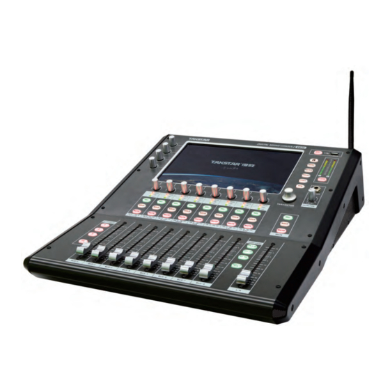
Introduction This digital mixer is designed with professional live performance as the standard. It is used for sound amplification in ballrooms, music halls, stage performances, live audio program recording and other application environments, with powerful featuresto meet the needs of the most demanding professionals. -
Page 43: Technical Indicators
Technical indicators Hardware Indicators Functional Indicators 26 channel input: 2 independent effector channels 12 channel microphone; Input channel Effector Effect types include: Hall, Room, 4 mono channel;2 stereo; Plate, Church, Delay, Chorus FI anger 3 digital stereo 12 channel output; Main output L/R;... -
Page 44: Hardware Structure And Installation
Hardware structure and installation STRUCTURE AND DIMENSION... -
Page 45: Interface Description
INTERFACE DESCRIPTION 1. Combined input interface It is used to connect a microphone or balanced analog line input signal. The XLR interface is used to connect a microphone, and the 6.35mm TRS in-line interface is used to connect balanced line signals. These interfaces can provide + 48Vphantom power. This mixer has 12 combined input interfaces. -
Page 46: Operation Panel Description
OPERATION PANEL DESCRIPTION 1. Main encoder knob It is used to quickly adjust the selected corresponding function parameters (such as EQ gain, dynamic parameters, channel-sent parameters, etc.). Most of the adjust able parameters of the mixer can be adjusted through the main encoder knob when selected. 2. - Page 47 5. Quick adjustment knob of the channel parameter It is used to quickly adjust common parameters in the channel editing interface.In the channel editing interface of the input channel, the knobs adjust channel Gain, EQ low-cut filter Low Cut, channel threshold value Gate, and channel pressure limit Comp from top to bottom. 6.
-
Page 48: Software Control
Software control SOFTWARE UPDATE You can contact the distributor of this product to obtain the latest software version. Software upgrade method: (USB flash drive upgrade) 1. Copy the upgrade package file (extension: .upk) to the root directory of the USBflash drive; 2. -
Page 49: Factory Reset
FACTORY RESET The mixer provides 2 levels of restoring settings. One is to restore the setting parameters of all channels, and the other is to clear all user data and completely restore the factory settings. Restore all channel settingsL: Click Setting Reset on the menu-global interface of the mixer to restore the settings of all channels of the mixer, including all input channels, bus channels and effector channels. -
Page 50: Monitoring Settings
Monitoring Settings This product includes a professional monitor selection system. The built-in monitor bus of the mixer sends signals to the MONITOR PHONES headphone monitor socket on the panel and the MONITOR OUTPUT speaker monitor socket on the back panel. You can obtain the signal of the monitor bus through these sockets. -
Page 51: Digital Output Channel Settings
Digital Output Channel Settings The digital output channel of this product can choose different source signals. You can send the signal of BUS7 & 8 or MASTER channel to the specified digital output channel and recording channel (AES / EBU, USB sound card, USB flash drive recording) as the source signal on the MENU-Digital page. -
Page 52: Account Settings
Account Settings This product has a built-in account password system, which can prevent playing accidents caused by accidentally touching the mixer. This product has no password by default. To set a password, you can click the Set Password button on the Menu-Password page. After the password is set successfully, the mixer will jump to the password entering page. -
Page 53: Network Connections
Network Connections You can use the mobile terminal to connect through the WIFI of the mixer, or directly connect to the computer with a network cable through the LAN port of the mixer to achieve remote control of the mixer. After connecting, enter the mixer's IP address in the browser on the mobile terminal or computer to load and use the control software on the web page. - Page 54 On the CONFIG page of the network, you can set the wireless / wired network connection of the mixer on the Wireless and Wired sub-pages. After setting, click the Save button to save. Wireless connection On the wireless connection page, you can set the WIFI network name (SSID) and network password (Security) of the mixer, and adjust the channel of the mixer.
- Page 55 This product provides 11 wireless channels from 2.412GHz to 2.462GHz for your use. According to different management domains, multiple channels can be selected in the Wi-Fi wireless spectrum range, for example, Europe (ETSI) is 13 and North America (FCC) if 11. Third-party software can help choose a Wi-Fi channel.
-
Page 56: Operation
Operation Login Interface When you set a password, the mixer will first enter the password entering page after startup, and you can use it normally after you enter the password correctly. For details on password settings, refer to 4. Software Control-Account Settings. Overview Interface This is the channel overview page that the mixer first enters. -
Page 57: Menu Setting Interface
MENU Setting Interface After pressing the MENU button, you will enter the menu setting page. This page includes the Global, Monitor, Digital, Password, and Network subpages, and you can update or reset the mixer, adjust monitoring settings, adjust digital output sources, set mixer passwords, and adjust network connection settings on these pages. -
Page 58: Preset / Snapshot Interface
PRESET / Snapshot Interface When pressing the PRESET button, you will enter the preset / snapshot interface. This interface displays all the presets of the mixer. Select the preset on the left and press Load to apply the preset; click the Save button to save the current settings of the mixer;... - Page 59 After pressing the Import button, you will enter the list of USB flash drive storage presets. You can press the Load button to directly apply the preset from the USB flash drive to the mixer, or you can press the Import button to import the preset file to the mixer for later use.
-
Page 60: Channel Copy Interface
Channel Copy Interface After pressing the COPY button, you will enter the channel copy interface. You can copy the channel settings from the list on the left to the channels on the right. First select the channel on the left list, and the right list will display the channel that can accept the pasted channel. -
Page 61: Efx Effector Setting Page
EFX Effector Setting Page After pressing the EFX button, you will enter the effector settings page. Click the RESET button to restore the parameters of each effector to their recommended values; click the EFFECT button to enter the effector selection interface, and enter the 7 effector and deactivation options (i.e., the NONE button) provided by the mixer. - Page 62 This product contains 4 kinds of reverb effectors, namely HALL reverb, ROOM reverb, PLATE reverb and CHURCH reverb. HALL reverb usually brings a sense of huge space; its high frequency attenuation is very obvious, and the attenuation time is usually the longest; ROOM reverb brings more intuitive sense of space, making people feel the existence of space clearly;...
- Page 63 3. Chorus Chorus combines two or more signals, one of which is unaffected, while the pitch of the other signal changes very slightly over time, resulting in rich and full sound. Chorus is often used to thicken the soundtrack and increase the texture of the guitar. Chorus can also be used carefully to thicken vocal tracks.
-
Page 64: Record And Play Interface
Record and Play Interface Press the REC / PLAY interface in the upper right corner, you will enter the record and play interface. When a USB flash drive is inserted, the list on the left side of the interface will display the music files in the USB flash drive (mp3, wav format). -
Page 65: Mixer Channel
Mixer Channel The IN1-8 layer contains 8 MIC / LINE IN analog input channels. The IN9-16 layer contains 4 MIC / LINE IN analog input channels and 4 LINE IN analog input channels. - Page 66 The ST IN layer contains 2 pairs of stereo analog input channels, a PLAY USB flash drive play channel, 1 SPDIF input channel, 1 USB sound card input channel, and 2 FX effector channels. The BUS1-8 layer contains 8 buses. All buses can be set as single-channel AUX output or linked as stereo SUB channel output.
- Page 67 DCA Marshalling Function:Press the BUS/DCA button for the second time to enter the operation page of DCA1-4 channel and press the selection button of corresponding DCA channel. Any input or output channels controlled by each DCA channel can be organized and managed, and the unified management of this DCA channel can be accepted, making the operation easier and more convenient for users.
- Page 68 In addition to its own EQ function, the MASTER channel also has an independent 31-band GEQ graphic equalizer function. Click the GEQ button to enter the function interface as above. Click ON to enable the graphic equalizer, click PRESET to save and import the graphic equalizer presets, and click RESET to reset the graphic equalizer settings.
-
Page 69: Dsp Function
DSP Function When you click a channel on the screen or press the channel's SEL button, you will enter the editing page of the channel. This page contains the most basic editing functions and DSP functions of the channel. Channel page The Channel page contains an Input column, a Main column, and a Send to column. - Page 70 Gate page The Noise Gate page displays the noise gate parameters of the channel. The noise threshold uses a threshold to determine its "open" (over Threshold) or "closed" (below Threshold) status. When the door is closed, the signal level is reduced or cut off completely. The threshold can be used to reduce the ambient noise picked up by the microphone when the sound source (instrument / vocal) is silent.
- Page 71 EQ page The EQ page displays the equalizer parameters of the channel. An equalizer adjusts the amplitude of an audio signal at a specific frequency. The EQ processing function of the input channel consists of a four-band parametric equalizer and a high-pass filter (HPF).
- Page 72 The EQ processing function of the input channel consists of a four-band parametric equalizer and a high-pass filter (HPF). ON: Equalizer switch. RESET: Reset to the default value (that is, the equalizer "returns to zero", and the frequency and Q value are reset to the default values).
- Page 73 Compressor page The compressor page displays the compressor parameters of the channel. The compressor will reduce the signal level over a certain threshold. ON: Noise gate switch. RESET: Reset to the default value. PRESETS: Call up the standard preset management pop-up box to save / load the compressor presets.
-
Page 74: Mute And Mute Group
MUTE and Mute Group There is a MUTE button above each channel fader, which can mute the corresponding channel. Each channel can be programmed into the corresponding mute group in the channel editing interface - Channel page - Main column. When the mute group button on the bottom left of the mixer is lit, the channels in the group are muted. - Page 76 9T0XR26S1A...
Need help?
Do you have a question about the XR26 and is the answer not in the manual?
Questions and answers