Table of Contents
Advertisement
Advertisement
Table of Contents
Troubleshooting

Summary of Contents for Cellwatch Frontier
- Page 1 System Installation & User Manual VERSION 4.0.0...
-
Page 2: Cellwatch Frontier
Cellwatch Frontier Intended Use Cellwatch Frontier is a battery monitoring system that monitors the state of health of batteries used to power UPS systems by measuring the battery voltage, current, temperature, and ohmic value. There are features planned for future releases that are currently not available in this version. Future software updates will be available for download. - Page 3 Cellwatch Frontier System Installation & User Manual Cellwatch Frontier is manufactured by: NDSL Inc. 4112 Blue Ridge Road Suite 210 Raleigh, NC 27612 (919) 790-7877 www.cellwatch.com...
- Page 4 Cellwatch Frontier System Installation & User Manual...
-
Page 5: Table Of Contents
Cellwatch Frontier System Installation & User Manual Contents ......................2 ELLWATCH RONTIER Intended Use ............................2 Regulatory Compliances ........................2 I – I ..................... 10 ECTION NSTALLATION UIDE Introduction ..........................11 Trademarks ............................11 Copyright ............................. 11 Life Support ............................11 Liability .............................. - Page 6 Cellwatch Frontier System Installation & User Manual Connecting a DCM ..........................43 DCM Connection Order ........................55 Installation: Frontier Electrolyte Level Detectors ................56 Specifications ............................56 How it Works ............................56 Wiring ..............................57 Hardware Installation Process ......................59 II –...
- Page 7 Cellwatch Frontier System Installation & User Manual Electrolyte Levels ..........................79 String/Channel Alarms ........................79 Temperature Probe Alarms ........................ 80 Current Alarms ............................ 81 Digital Input Alarms ..........................81 SNMP ..............................82 DNP3 ..............................82 Software Activation ..........................82 Upgrade Software ..........................82 Cellwatch Central ..........................
- Page 8 Cellwatch Frontier System Installation & User Manual Type and Assignment .......................... 98 Configuring Frontier Electrolyte Level Detectors (FEDs) ............... 101 Configuration: Battery Design ......................101 Calibration ............................102 Alarm Status in User Interface ......................103 Other FED Diagnostic Functions ......................103 Common Errors ..........................
- Page 9 Cellwatch Frontier System Installation & User Manual Integration: Cellwatch Central ....................124...
-
Page 10: Sectioni - Installation Guide
Section I – Installation Guide... -
Page 11: Introduction
This guide will walk through the installation of the Cellwatch Frontier unit, the Data Collection Modules (DCM), Temperature Probes (TP), Current Transducers (CT) and Frontier Electrolyte Detectors (FEDs). Instructions on accessing and configuring the Frontier unit can be found in the User Guide and Battery Configuration Guide. -
Page 12: Important Safety Information
Cellwatch Frontier System Installation & User Manual This warranty does not apply to any part of the system supplied by the customer or problems arising from normal wear and tear or failure to follow instructions. Important Safety Information READ THE FOLLOWING INFORMATION CAREFULLY. SAVE ALL INSTRUCTIONS FOR FUTURE REFERENCE! ... -
Page 13: Cellwatch™ Service And Support
Cellwatch Frontier System Installation & User Manual To completely disconnect this apparatus from the AC mains, disconnect the power supply cord from the AC receptacle. WARNING: To reduce the risk of fire or electric shock, do not expose this apparatus to rain or moisture. -
Page 14: Installation Safety
Cellwatch Frontier System Installation & User Manual Installation Safety The following safety precautions should be observed before any work is performed on the system containing the NDSL product. This system is intended for installation by personnel who are trained and qualified to recognize the hazards associated working with such systems and are familiar with the safety precautions required to avoid possible injury. -
Page 15: Frontier Hardware Specifications
Cellwatch Frontier System Installation & User Manual Frontier Hardware Specifications Power Supply AC Input 100-240 VAC @ 50-60Hz, 10W Option 1: 20-70 VDC, 10W (Alternative) DC Input Option 2: 70-150 VDC, 20W Option 3: 100-240 VDC, 20W Permitted Mains Supply Variations... -
Page 16: Dcm Specifications
Cellwatch Frontier System Installation & User Manual Temperature Sensor Range 2-80°C +/- 1°C Current Transducer 2 (Wall Mount) Quantity 4 (Rack Mount) Float Only Range Supported Directional / Bi-Directional 50A, 100A, 300A, 600A, 1000A Ranges (+/-) Ethernet Ports 1 on Wall Mount or Rack Mount units... - Page 17 Cellwatch Frontier System Installation & User Manual Enhanced Measurement Range Resolution Accuracy Characteristics (Requires Activation) Voltage 0 to 80V 0.1% +/- 5mV Ohmic Value 0 to 1mΩ 1µΩ 2% +/- 8µΩ 1 to 65mΩ 1µΩ 1.5% ° ° ° Cell Temperature (requires DCM5T) 2 to 80 0.01...
- Page 18 Cellwatch Frontier System Installation & User Manual DCM6-L Specifications Description DCM6-L Environment Operating temperature 0 to 60ºC Relative Humidity 5 - 85% non-condensing Maximum Altitude 3,000 meters (10,000ft) Power supply full functionality 4 - 12 Volts DC Power supply voltage &...
- Page 19 Cellwatch Frontier System Installation & User Manual Please note that the DCM6-H has a lower quiescent current than other DCM models and so must not be mixed on the same string of containers. It can however operate on the same fiber optic loop as previous DCM models.
- Page 20 The DCM6-R is designed to measure string ripple voltage on 2 volts cells up to a maximum string voltage of 300 volts. The white wire should be connected to the negative side of the Frontier cabinet fuse and the brown wire to the positive side. The DCM6-R is usually configured to be the last DCM on the fiber loop.
- Page 21 Cellwatch Frontier System Installation & User Manual voltage protection with an external fuse in the harness. The DCM6-L-CC uses 3-amp current to get the most accurate ohmic value measurement. DCM6-L-CC Specifications Description DCM6-L-CC Environment Operating temperature 0 to 60ºC Relative Humidity...
- Page 22 Cellwatch Frontier System Installation & User Manual The DCM5-DS looks similar to the DCM5T, but it has an extra black wire that is connected to the same post as the yellow sense wire at the center of the 48-volt string. This wire allows the DCM to have two independent Ohmic current sources each operating over half of the string.
-
Page 23: Critical Distances
The following are critical distances for a Frontier system. Current transducers and temperature probes have a maximum cable distance of 150 feet. Fiber segments, which run between the Frontier device and DCM units, cannot exceed distances of 150 feet. The leads of a standard DCM 6 (L or H) can be factory purchased at 40 inches or 80 inches long. -
Page 24: Mounting Options
80 in. Optional DCM6 (72 inches for DCM5) Mounting Options The Frontier system is available in two different models. A wall mount model comes equipped with two side wings that allow the unit to be mounted to a hard non-conductive or grounded surface using a No. -
Page 25: Exposed Installations
It is very important that the placement of a strain relief for the power cable, or even the mounting location of the Frontier system itself, does not in any way restrict access to, or inhibit the action of disconnecting the power cable from the unit. - Page 26 Short (1-5 seconds) Clear alarm relays The USB ‘A’ port allows for the connection of a thumb drive to copy or remove files from the Frontier system. This function is not supported at this time. The mini-USB (2021+) port allows a PC to be connected directly to the Frontier system and access the GUI via a USB to Ethernet bridge connection.
-
Page 27: Frontier Back Panel
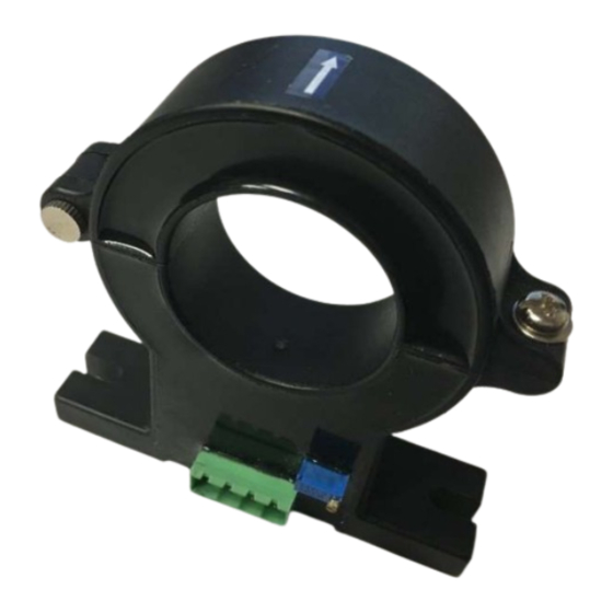
Ethernet Sensor Inputs The back panel of the Frontier wall mount model. The rack mount Frontier (not pictured) features a similar layout. Current Transducer (CT) Current transducers can be connected to the Frontier system to monitor for discharge and charge events. - Page 28 Direction of current transducer on positive or negative bus cable The standard current transducer used in a Frontier system has a 100A range to monitor for discharges. Current transducers with different ranges have been approved for use with the Frontier and can be found in the table below.
- Page 29 Cellwatch Frontier System Installation & User Manual 100A and 600A black low noise current transducer wiring 50A, 100A, 300A green current transducer wiring 600A and 1000A larger black current transducer wiring Note: Only current transducers provided through NDSL are tested and approved to work with the Frontier unit.
- Page 30 Four digital inputs are provided. Each input shares a common ground that is optically isolated from the Frontier device and the power supply. Digital inputs can be used to incorporate third party systems and notifications into the Frontier module. This may include devices such as ground fault monitors, electrolyte level detectors, hydrogen sensors, liquid/electrolyte leak detection systems.
- Page 31 Frontier from a UPS to ensure the Frontier module can properly detect and capture discharge events. If AC mains is used without a UPS, then the Frontier unit will power off in the event of power loss and will remain off until AC power is restored.
-
Page 32: Connection Strain Relief
Frontier will generate a battery alarm and a DCM Failure error will appear in the user interface. The Battery Alarm relay will trip if it is configured to do so. Frontier will attempt to reestablish communications every hour for 48 hours. After 48 hours have passed, communications will not be reestablished until all hardware issues are resolved and the user manually resumes scanning in Diagnostics. -
Page 33: Preparing The Battery
Cellwatch Frontier System Installation & User Manual 2. Avoid fixing the DCM onto metalwork. Electrical noise can be radiated from the metalwork even if the frame is grounded and this can cause reading variations within the DCM. 3. Always place the DCM tab washers next to the battery post or strap. Never place any stainless- steel material between the battery post and the tab washer. - Page 34 Cellwatch Frontier System Installation & User Manual Ensure that the tab washers are fitted as close to the post of the cell or container being monitored. Make sure that the tab washers are either against the battery post or against the inter-cell strap.
- Page 35 Cellwatch Frontier System Installation & User Manual As shown above, there should never be any other material between the straps or post and the tab. Ensure that the tab is directly against the lead post of the cell or on top of the load carrying cables.
-
Page 36: Battery Configurations
Cellwatch Frontier System Installation & User Manual unused posts; the unused channel must then be nulled in the Frontier web interface. Channel 4 should always be considered the first channel to be nulled, followed by 3, then 2. This is covered in further detail in the next few sections. - Page 37 Cellwatch Frontier System Installation & User Manual VRLA installation on shelves or small cabinets VRLA installation on open racks VRLA stacks with front access VLA (flooded) cells on open racks The DCM 5T is necessary for thermal runaway protection on open rack systems due to the temperature variances across the string.
- Page 38 Cellwatch Frontier System Installation & User Manual Standard DCM wiring to a string that is divisible by four VRLA installation on four-jar trays In a four-jar (or mono-bloc) per tray configuration, one DCM per tray should be used. If possible, disconnect battery trays to a safe voltage.
- Page 39 Cellwatch Frontier System Installation & User Manual Br, R Br, R Bl, W Bl, W DCM #1 DCM #2 Fiber Loop If a tray is equipped with isolation quick disconnects, it is important not to install the DCM across a quick disconnect.
- Page 40 Cellwatch Frontier System Installation & User Manual 4. Place two tab washers on the next positive post connected on the opposite side of the strap connected to the dual tabbed negative post. This is the connection for the white wire of DCM n and the brown wire of DCM n+1.
- Page 41 Cellwatch Frontier System Installation & User Manual nulled channels on one of the DCMs, or a single channel on two DCMs. In the example below, channel 4 is nulled, meaning that the Green, Blue, and White wires would terminate on the same post.
- Page 42 If the cells monitored cannot supply enough voltage to power the DCM, then the DCM must be wired across more cells than typically connected. When wired this way, each channel in Frontier will measure across two jars. This will affect ohmic and voltage readings but will still allow the user to monitor the health of their battery.
-
Page 43: Connecting A Dcm
Cellwatch Frontier System Installation & User Manual If the number of cells in the string is not divisible by four, ensure each DCM6-L is wired across at least three cells. Most of the DCM units on the string will monitor four cells with the last one, two, or three (depending on the remainder) monitoring three cells. - Page 44 Cellwatch Frontier System Installation & User Manual Standard maintenance around the DCM (i.e. replacing a cell) When replacing a cell, the DCM connected to or across the cell that is being replaced should be removed entirely. Document the location of the wires and the directional path of the fiber optics. Using colored tape can help ensure that the fiber optics are connected properly.
- Page 45 The ohmic-value of that inter-aisle link is clearly visible on the graph and will skew the averages for the entire string. However, Frontier can automatically adjust for this in setting ohmic value alarms. Altering the installation to remove the inter-tier connector can remove readings like this from the graphs.
- Page 46 Cellwatch Frontier System Installation & User Manual In Frontier, one or more channels can be specified as an inter-cell link, an inter-tier link, or a charger cable. Frontier will separate these channel readings from cell readings in order to provide better scaling with graphs while still allowing the link(s) to be monitored.
- Page 47 Terminal (Post) Clips The post clip that ships with your Frontier system is shown in the photo below. These clips are available in ¾ and 1-inch sizes. DCM sense leads will be connected to the post clips via the tabs on the top of the clip.
- Page 48 Cellwatch Frontier System Installation & User Manual When installing the post clip, take care to not push off any battery grease that might be on the side of the posts. The no-ox or battery grease creates an effective barrier against corrosion of the post. The best way to achieve this is to ‘hook’...
- Page 49 The DCM6-R measures string ripple and string voltage. It is usually connected as the last DCM on the fiber optic loop. Mount the DCM6-R on a jar or DIN-rail near the Frontier cabinet. Ensure the cabinet fuse is open so no power is supplied to the system. Then connect the brown lead to the positive side of the cabinet fuse and the white lead to the negative side of the cabinet fuse.
- Page 50 Cellwatch Frontier System Installation & User Manual The DCM6-R is certified to work up to 300 volts. For systems with a string voltage less than 300 volts, use one DCM6-R connected directly across the string. When the string voltage is greater than 300 volts, we supply two DCM6-R’s and then wire each DCM across half the string.
- Page 51 Cellwatch Frontier System Installation & User Manual Wiring for a system less than 300v. For over 300v, use a DCM6-R-600 across the entire string. Section I – Installation Guide-51...
- Page 52 DC power supply to the negative of the battery. Channel one of each CC unit is used for the measurement (between the red and orange leads). DC power supply units used to power the DCM6-L-CC mounted inside Frontier enclosure. Incorporate the DCM6-L-CC into the fiber loop with the DCM6-L or DCM5 string. Standard designs are to locate the DCM6-L-CC as the last two DCMs or as the first and last DCM units in the loop.
- Page 53 Cellwatch Frontier System Installation & User Manual Connect the red lead to a post clip on the most positive/most negative posts of the battery. Black should connect to a ring tab on the most positive/most negative posts of the battery. See the wiring diagram below.
- Page 54 Individual cell or negative post temperatures can be monitored with the use of the DCM 5T or DCM 6T. The temperature probe is integrated into the wiring leads of the DCM. The Frontier interface will recognize that the DCM connected is equipped with this feature automatically and will display the readings on the homepage.
-
Page 55: Dcm Connection Order
DC voltage for the plant. In these configurations if a DCM is monitoring on the individual cell level, then two DCM channels will be joined together (i.e. readings will be zeroed and nulled). The Frontier automatically accounts for these channels based on the voltage and the ohmic value readings. -
Page 56: Installation: Frontier Electrolyte Level Detectors
Guide. Battery configuration information can be found in the section titled Battery Design. Installation: Frontier Electrolyte Level Detectors This section will provide an overview of the installation and functionality of the Frontier Electrolyte Level Detector (FED) devices. Specifications FED Specifications Description... -
Page 57: Wiring
IN of the next FED unit, until the last FED unit in the system is reached. The last FED unit in the series is known as the “End of Line” (EOL) and reports the end of the string to Frontier. The OUT port will not be used on the EOL unit. - Page 58 The Interface Module allows for AC or DC power input (see above). For DC input, the Interface Module is wired to an unused CT port on the Frontier device in order to obtain 24V. For AC input, the Interface Module comes with an AC/DC adapter which can be plugged into a UPS outlet.
-
Page 59: Hardware Installation Process
Cellwatch Frontier System Installation & User Manual Example wiring of FED Interface Module using DC power from the Frontier’s CT port. Hardware Installation Process The following section outlines the hardware installation process for FED units. Preparation Each battery container should be thoroughly cleaned before FED devices are mounted. Debris and acid should be removed from the case to ensure an accurate measurement of electrolyte levels. - Page 60 Cellwatch Frontier System Installation & User Manual Note: Before proceeding to the next step (CAT5 connections), allow the FED tape to bond to the jar. This is best achieved by delaying connecting the CAT5 cables until 1-2 hours after the FEDs have been placed on the jars.
- Page 61 Powering up Upon powering up, the FED units will need to adjust to the battery room environment. It is required to wait at least 5 minutes while the FED units stabilize before configuring them in the Frontier user interface. For new installations, all FEDs will show fast flashing green LEDs the first time they are powered up to indicate that they have not yet been calibrated.
-
Page 62: Section Ii - User Guide
Section II – User Guide... -
Page 63: Introduction
Connect a micro/mini-USB cable between a computer and the Frontier module. When a computer is connected to the Frontier device for the first time, it will attempt to install a compatible USB driver that will bridge the USB to a virtual Ethernet port on the Frontier device. -
Page 64: Using The Ethernet Port
That’s it! The Home page will load, and the Frontier interface may report one or more errors on screen. No need to worry; this is simply because the Frontier device has not been configured yet. The rest of this manual will cover building a battery configuration using Battery Design, setting alarm limits for the measurements that Frontier collects and keeps track of, and configuring various hardware components. -
Page 65: Home Page
Module Name/Location Home Page The Home page is the first page shown upon logging in to the Frontier web interface. On this page, pertinent battery information will be displayed once measurements and alarm status are available from the Frontier unit. -
Page 66: Alarm Viewer
Alarm Viewer To view a log of past and present alarm events in Frontier, choose the Alarms menu in the Navigation Bar at the top of the page. The Alarm Viewer can be sorted or filtered, as well as exported to a Comma- Separated Values (CSV) file. - Page 67 Cellwatch Frontier System Installation & User Manual To filter the list, click the ‘Filters’ to expand the options. Then choose which column you want to filter by. Under ‘Apply a Filter’, choose which value to apply and the data in the table will refresh. The column you choose to filter by will determine your ‘Apply a Filter’...
- Page 68 Cellwatch Frontier System Installation & User Manual The Cell (cell, intercell strap, intertier strap, or charger cable) or Cell/probe Probe (CT, TP, DIB, or FED) that triggered the alarm. The Cell (cell, intercell strap, intertier strap, or charger cable) or Cell/probe No Probe (CT, TP, DIB, or FED) number that triggered the alarm.
-
Page 69: History Graphing
Cellwatch Frontier System Installation & User Manual Previous Page: Go to the previous page of alarms. Next Page: Go to the next page of alarms. Last Page: Go to the last page of alarms. History Graphing History graphing can be accessed by selecting History on the Navigation Bar. The table below can be used to help identify the types of graphs that can be displayed. -
Page 70: Using The Graphing Functions
Cellwatch Frontier System Installation & User Manual Discharges (Discharge Data Only) Select Discharge Event Displays all recorded discharge data for selected event. Data to Display Batteries Plot one or more Batteries. Strings Plot one or more Strings. Channels Plot one or more Channels. -
Page 71: Reports
Hide all: Users can disable all selected cells to clear the graph. Reports The Frontier device can generate a battery report on the state of the system, including battery manufacturer and model, installation date, and the latest voltage, ohmic value, and temperature measurements for each cell and strap. -
Page 72: Frontier Settings
CSV or HTML page or delete from the system. Frontier Settings The Settings drop-down menu contains configuration information for the Frontier system. Here users can set alarm limits, change the battery configuration, as well as perform diagnostics on the Frontier module. Battery Design In Battery Design, users can create a new battery configuration or edit the existing battery configuration for the Frontier system. -
Page 73: General
The following settings can be changed on the Device Settings page: General Site Name – Sets the name of the Frontier system seen in the upper left-hand corner of the page. This can also be used to identify the site when accessing the system remotely. ... -
Page 74: Network Settings
IP distributed by the network. Users will be required to restart and log into the Frontier device once this setting is changed. It is best to perform this operation if you know what IP will be assigned by the network administrator or if connected via the USB service port. -
Page 75: Https Support
HTTPS Support The Frontier web interface uses HTTP by default but can be set up to also use HTTPS. Frontier generates its own unique encryption key (the private key) which is signed by an SSL certificate from a Certificate Authority (CA) in order to encrypt traffic between the Frontier device and the user’s web browser. - Page 76 Cellwatch Frontier System Installation & User Manual Example of a Frontier generated CSR. Begin and end markers must be included when requesting a certificate. The CSR is stored on the Frontier device and can be retrieved again at any time by navigating to the Network page.
-
Page 77: Commissioning Data
Frontier configuration will be changed to use only HTTP and is reflected on the next device restart. This is to ensure that the Frontier is not left with HTTPS enabled but no certificate. For example, if the Frontier loses power after deleting a certificate, it will start up with HTTPS disabled. -
Page 78: Hardware Relay
Enter the maximum capacity (rating) of the current transducer. For example, a CT with an input of 50A is capable of measuring a discharge current of up to 50A. In Frontier, this CT would be configured as a discharge only CT with a capacity of -50. -
Page 79: Electrolyte Levels
‘full’ level. This process should be run when installing FED units for the first time on a system. To update FED status, a Manual Scan can also be sent to the FED string from this page. The Frontier system will automatically scan the FED string every 15 minutes. -
Page 80: Temperature Probe Alarms
Cellwatch Frontier System Installation & User Manual configuration. The option to set All Channels will set all ohmic channels available based on the configuration. Low Voltage: Alarm will occur when a cell voltage drops below the set value. This is useful to ensure a proper charge voltage on a cell. -
Page 81: Current Alarms
Low Float: This setting will enable Frontier to monitor for low float current, or a break in continuity within the battery. This limit should be set above zero but significantly below the normal float charge current. A typical low float limit is at least 20mA. -
Page 82: Snmp
Upon completion, the device will require a reboot. Press the Restart Device button to reboot the Frontier system. Note: Software upgrades will not occur if the Frontier system clock is not set correctly. Updates with a release date beyond the Frontier system time and date will not install. -
Page 83: Cellwatch Central
Central. Backup and Restore Frontier has the ability to create a backup file which will contain all history and discharge data, as well as all device configuration files and settings. The most recent backup created will remain on the device, giving the user the option to download the file to local storage at any time. - Page 84 Cellwatch Frontier System Installation & User Manual Depending on the amount of data on the device, Frontier may take from a few seconds to 20 minutes to complete the backup. Navigating away from this page will not interrupt the backup process.
-
Page 85: Diagnostics
The amount of time needed for the restore process will be largely dependent on the size of the backup and the speed of your connection to the Frontier device. A backup file that is 100 megabytes (MB) in size takes roughly 2 minutes when restoring over a local area network (LAN). It is not recommended attempting to restore over a slow or unstable connection, as the process may take hours or fail to complete. -
Page 86: View Frontier Log
The View Frontier Log contains messages from the underlying software within the Frontier system. Viewing the Frontier log can be beneficial in troubleshooting any issues occurring with the Frontier unit. An option to save the complete log of events to a PC or onto a network storage device is available by clicking the Download Frontier Log button. -
Page 87: Tests And Actions
DCM until the signal is returned to the Frontier module. This test can be used to troubleshoot a break in the fiber optic loop of a Frontier system by using the DCM units to identify where the break has occurred in the loop. -
Page 88: Data Interpretation
Cellwatch Frontier System Installation & User Manual Data Interpretation Proper use of the battery monitoring system is critical to monitoring battery health. If the Frontier system is not monitored regularly or connected to proper alert management systems, users will not know of potential issues exposing their battery system to risks. -
Page 89: Current Alarms
Setting a charge limit does not place the Frontier system into alarm if triggered, but it can be used to optionally monitor charge events for graphing and data analysis. - Page 90 An example of Frontier monitoring a charge event. Low float current (continuity) Frontier includes a low float alarm that is triggered when current measured is less than the intended float charge. This can be indicative of a battery internal disconnect or possibly switched-off charger. This limit must be less than the charge current limit, and a Float Charging Current Probe (FCCP) should be used as the charge CT in a logical CT configuration.
-
Page 91: Section Iii - Configuration Build And Hardware Integration Guide
Section III – Configuration Build and Hardware Integration Guide... -
Page 92: Introduction
Which wiring pattern is being used? Frontier has the ability to measure inter-cell straps or links separately from cells. This allows for ohmic value analysis and trending that isolates and monitors the changes of the cell and the straps independently. -
Page 93: Batteries
How many batteries? Up to four batteries can be monitored by a single Frontier unit. This is due to the limited number of CT ports available in Frontier. Each battery must have at least one CT assigned to it. Edit this field with the number of batteries in the system and the page will update with available settings for each. - Page 94 Assigned Digital Input Bits – Number of digital input bits (DIB) to be assigned to a string. Channel Count – The total number of DCM channels in the Frontier system. Each DCM has four channels, so this number can be calculated by multiplying the number of DCM units in the system by four.
- Page 95 Cellwatch Frontier System Installation & User Manual In Frontier, each string has its own channel map. If all strings require modifications to the channel map, then the changes must be made for each string. Electrolyte Level Detectors (FEDs) This string does not have FEDs/This string has FEDs – Select Change to alter FED settings within this string.
-
Page 96: Saving Your Configuration
Cellwatch Frontier System Installation & User Manual Press the Next button at the top of the page to continue to the next section. Saving your configuration Once the battery configuration is completed, it will need to be saved in order for the proper configuration files to be written. -
Page 97: Configuring Temperature Probes (Tp)
Note: The cells will appear grey after you have saved a new Battery Configuration. Once alarm limits have been set and the Frontier system executes an initial scan, individual channels will appear green or red if in an alarm state. -
Page 98: Configuring Current Transducers (Ct)
Type and Assignment The CTs selected in the Battery Design wizard are available to be configured by Type and Capacity. Frontier allows the use of different styles of CTs and different monitoring capabilities. Section III – Configuration Build and Hardware Integration Guide-98... - Page 99 CTs can be assigned to it. Reading The value displays real-time readings from any current transducers connected to the Frontier unit. These readings can be used to verify the configuration is correct and to assess whether a CT should be zeroed.
- Page 100 5. Once LEDs have gone out, cycle the power on the converter box one more time. 6. In Frontier, go to the settings menu and select Configure CTs. The CT should be set as a charge only CT with a range of 5 amps.
-
Page 101: Configuring Frontier Electrolyte Level Detectors (Feds)
FEDs are not flashing green. Configuration: Battery Design The battery configuration must be updated to include any new hardware that is added to the Frontier system. The saved settings of the current battery configuration can be modified to easily add the number of installed FEDs. -
Page 102: Calibration
Cellwatch Frontier System Installation & User Manual Calibration After configuring the number of FED units in Battery Design, the FEDs will need to be calibrated to accurately detect low electrolyte levels. Calibration of FED units is done in Settings by selecting the Electrolyte Levels menu option. -
Page 103: Alarm Status In User Interface
Errors. 3. Press the Calibrate button. The button state will change to “Calibration Requested” while the Frontier system calibrates each FED unit in series. a. Quick Calibrate sets the ‘full’ level for each FED unit. b. Full Calibrate will power cycle the FED units and set their addresses (enumerate operation), it will then calibrate the units at the ‘full’... - Page 104 Cellwatch Frontier System Installation & User Manual Auto Calibrate Scheduled Time sets the time each day for the auto calibration to occur. The final option on this tab is to Enable Detachment Detection. Enabling this option turns on all falloff and plate dimming features.
- Page 105 Cellwatch Frontier System Installation & User Manual If an error state is reached, the Home page will change the color of that FEDs indicator to gray. The Status tab will then give some additional information as to the reason for the error. Likewise, a ‘Not Reliable’...
-
Page 106: Common Errors
FED. Force a manual scan in Diagnostics or allow the FED to update on the next hourly scan. A break in FED communications will be easy to spot on the Frontier Home page. The location of the break can be seen as the first cell that is colored grey in a string. The previous FEDs in the string returned their readings but the break in communications began at the FED that is colored grey. -
Page 107: Configuration Build Examples
Cellwatch Frontier System Installation & User Manual Configuration Build Examples Standard System with FEDs Example Configuration: 1 Battery, (2) 60 jar strings with standard DCM wiring, 2 temperature probes, 2 current probes 1. Select Battery Design from the Settings menu. -
Page 108: Inter-Cell Straps
Cellwatch Frontier System Installation & User Manual 15. Click Next. 16. Enter in the operator password of ‘deafcat’. 17. Click Save and wait for the “Settings Saved” confirmation. 18. Select Home from the Navigation Bar to see the new readings. - Page 109 Cellwatch Frontier System Installation & User Manual 10. Make no changes to the Electrolyte Level Detectors (no FEDs) and Temperature Compensation (no). 11. Click Next. 12. Enter in the operator password of ‘deafcat’. 13. Click Save and wait for the “Settings Saved” confirmation.
-
Page 110: Charger Cables
Cellwatch Frontier System Installation & User Manual 20. Assign alarms to the Frontier unit. Charger Cables Example Configuration: 1 Battery, (1) 60 jar string measuring charger cables, with DCM 5T, 2 temperature probes, 2 current probes 1. Select Battery Design from the Settings menu. -
Page 111: Dcm6-R
Cellwatch Frontier System Installation & User Manual 15. Select Configure CTs in the Settings menu, located in the Navigation Bar. 16. Select the Type of CT that is connected to the corresponding ports. 17. Select the Capacity rating of the CT. -
Page 112: Battery Configuration Troubleshooting
Cellwatch Frontier System Installation & User Manual 10. Make no changes to the Electrolyte Level Detectors (no FEDs) and Temperature Compensation (no). 11. Click Next. 12. Enter in the operator password of ‘deafcat’. 13. Click Save and wait for the “Settings Saved” confirmation. -
Page 113: Ct Readings Incorrect
Cellwatch Frontier System Installation & User Manual 4. Walk back through the Battery Design to make sure the configuration file was built correctly. Choose Use Saved Settings and check the current layout. Make changes as needed. CT Readings Incorrect 1. Check CT wiring at Frontier connection. -
Page 114: Section Iv - Integration Guide
Section IV – Integration Guide... -
Page 115: Introduction
Cellwatch Frontier System Installation & User Manual Introduction This guide will walk through integrating the Frontier device into a SCADA (Supervisory Control And Data Acquisition) environment or BMS (Building Management System). Frontier supports Modbus TCP/IP, SNMP (SNMPv2c, SNMPv3), and DNP3 communication protocols. Note that collecting battery data alone is not a suitable solution to monitoring batteries. - Page 116 Frontier data is sensitive. Write access to the Frontier is not supported. Adding and removing trap recipients The Trap Management section of the page allows you to add or a remove a trap recipient. Frontier is designed to send SNMPv2c unacknowledged traps (TRAP), and any number of recipients can be specified.
-
Page 117: Snmpv3
Once the required fields are completed, click the Add user button to add the new user to the system. Clicking Add user will immediately add the user to the USM user table, so a restart of the Frontier device is not required. -
Page 118: Advanced
User dropdown box, then fill in the IP address or hostname of the trap recipient. To add the trap recipient, click the Add trap recipient button. Any number of SNMPv3 trap recipients can be added to a Frontier system. Inform traps are not supported in Frontier. -
Page 119: Integration: Dnp3
To enable the DNP3 service, toggle the checkbox next to Enable DNP3 under the General tab. Other configuration options under General include: Number of concurrent masters: Select how many master stations will connect to Frontier to retrieve data. Frontier supports 1 or 2 master stations. ... - Page 120 The description for each option can be found in the table below. Link Settings Description The local or “slave” DNP3 address of Frontier. The Frontier link Frontier link address (Source address should be unique on the user’s network. The address must be address) between 0 and 65519.
-
Page 121: Session
Cellwatch Frontier System Installation & User Manual IP Settings Description The type of IP connection to establish with a master station. Frontier IP Mode supports TCP mode only. The port to listen on for incoming TCP requests. The port must be TCP listen port between 1025 and 65535. -
Page 122: Events
Cellwatch Frontier System Installation & User Manual Link Status Description The amount of time (in seconds) to keep connection sessions open. “Keep-alive” interval Frontier will keep a session open for the specified amount of time (seconds) after losing connection with a master station. Select/Execute Timer Description... - Page 123 Cellwatch Frontier System Installation & User Manual The description for each option can be found in the table below. Object Type Description (1) packed format: Send binary inputs as single bit packed. Binary inputs (2) status with flags: Send binary inputs with status.
-
Page 124: Files
Cellwatch Central, navigate to the Cellwatch Central page in the Settings menu. The IP address and port are needed in order for Frontier to establish a connection to Cellwatch Central. Once you have entered in the IP address and port of the Cellwatch Central server, select the checkbox to enable. - Page 125 Verify that both the Frontier system and Cellwatch Central server have network connectivity. It is possible that one or more firewalls are between the Frontier device(s) and the Cellwatch Central server. Ensure that the proper ports are opened in any existing firewall before attempting to connect a Frontier system to Cellwatch Central.
Need help?
Do you have a question about the Frontier and is the answer not in the manual?
Questions and answers