
Summary of Contents for ICP 1
- Page 1 ICP-1 USER MANUAL Volumetric Filling Machine with variable cylinder assembly (Sizes – 50ml, 125ml, 250ml, 500ml, 750ml, 1250ml, 2000ml) March 2022...
-
Page 2: Table Of Contents
3.12 HANDWHEEL AND DIGITAL SCALE 4 SETUP PROCEDURE 4.1 ASSEMBLY 4.1.1 HOPPER 4.1.2 INLET CONNECTION 4.1.3 INSTALLING AND CHANGING NOZZLES 4.3 CONNECTION OF COMPRESSED AIR SUPPLY SAFETY INTERLOCK 4.4 EMERGENCY SAFETY STOP SYSTEM 5 PREPARING MACHINE FOR FILLING 5.1 B EFORE YOU RUN PRODUCT IN THE MACHINE 5.2 C... -
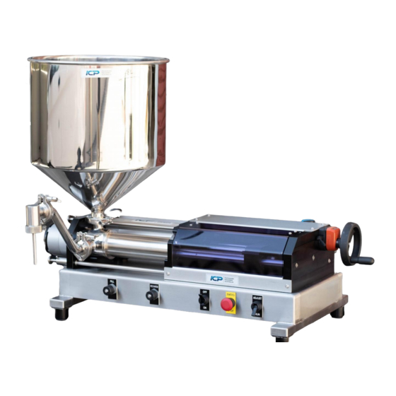
Page 3: Introduction
The ICP-1 incorporates one volumetric filling cylinder with a rotary or spool valve. Purpose-built for either benchtop operation, it’s portable and easily transferrable between areas. The ICP-1 includes a rotary valve set up that allows filling of products up to 60 C (and a spool °... -
Page 4: Safety
FROM THE MANUFACTURING PROCESS. 2 SAFETY ICP Packaging machines are custom-built machines designed specifically for an application and/or purpose outlined by the customer and the requirements to fulfil a project. This machinery is built with safety measures to protect the machine from damage and limit the risk of injury to the user. -
Page 5: Emergency Stop Button (E-Stop)
It’s best to start slow and increase the speed to a point where you get a smooth, even flow. 3.5 RECHARGE P a g e ICP-M2RV Manual © Copyright 2018 SMICP Pty Ltd - All rights reserved... -
Page 6: Handwheel And Digital Scale
NOTE: only needs to be lightly nipped up “do not overtighten”. NOTE: the red digit is a 10 of a mm. I.e. Setting the scale to 32 = 4 SETUP PROCEDURE 4.1 ASSEMBLY P a g e ICP-M2RV Manual © Copyright 2018 SMICP Pty Ltd - All rights reserved... -
Page 7: Hopper
December 14, 2021 The ICP-1 can be set up with multiple differing options (E.G. different cylinder sizes, hopper or inlet feed, and numerous nozzle options to suit your project). 4.1.1 HOPPER Hopper choice will vary depending on the setup for your machine, from small to extra-large. - Page 8 ON/OFF switch OFF, depressing the footswitch will cause the machine to cycle once, with the product piston finishing in the right hand (fully recharged) position. P a g e ICP-M2RV Manual © Copyright 2018 SMICP Pty Ltd - All rights reserved...
-
Page 9: Connection Of Compressed Air Supply
IMPORTANT THAT NO OBJECTS ARE INSERTED INTO THE VALVE PORTS AT ANY TIME. DOING SO CAN RESULT IN SEVERE DAMAGE TO THE MACHINE AND OR SERIOUS PERSONAL INJURY. P a g e ICP-M2RV Manual © Copyright 2018 SMICP Pty Ltd - All rights reserved... - Page 10 Ensure that the Hand Valve is turned to EXH (off position). Adjust air pressure to 600 kPa (87 psi) via the knob on the Filter/Regulator Unit. The ICP-1 requires a constant 87psi to the machine. It is also recommended that the air supply has a dryer installed.
-
Page 11: Safety Interlock
The ICP-1 is capable of sucking the product directly from a source as long as the product is not too thick and the source is not too far from the filler. The best... -
Page 12: Fill Volume Adjustment
NOTE: only needs to be lightly nipped up, "do not overtighten". NOTE: the red digit is a 10 of a mm. Setting the scale to 32 = 11 | P a g e ICP-M2RV Manual © Copyright 2018 SMICP Pty Ltd - All rights reserved... -
Page 13: Operating & Adjustments
OPERATING & ADJUSTMENTS 6.1 CONTINUOUS CYCLING Ensure that Emergency Stop Button is released - ADJUST/RUN switch is in the RUN position. -
Page 14: Recharge Rate
DO NOT ATTEMPT TO ADJUST VOLUME WHEN THE PRODUCT CYLINDER IS FULLY RECHARGED AND THE ADJUSTING MECHANISM IS UNDER LOAD. PREVENTATIVE MAINTENANCE 7.1 GENERAL Your ICP-1 Filling Machine is designed for minimum maintenance operation. Its design features and construction materials eliminate the necessity for an extensive preventative maintenance routine. 13 |... -
Page 15: Seals
Drain the Air Filter Bowl of accumulated dirt and water by loosening the plastic screw at the base of the clear plastic bowl. Re-tighten by hand. 14 | P a g e ICP-M2RV Manual © Copyright 2018 SMICP Pty Ltd - All rights reserved... -
Page 16: Weekly Maintenance
7.5 3 MONTHLY MAINTENANCE Regular daily maintenance plus; 7.5.1 Filling Machine Remove the top cover and apply a smear of grease to Volume Adjusting Threaded Shaft. Inspect and apply a smear of light oil to the product piston rod and bearing rods. -
Page 17: Rotary Valve Model
Remove tri-clover clamp from product valve outlet and remove nozzle gooseneck fitting complete with nozzle and rubber seal. 8.2.1 Rotary Valve model Loosen the two T nuts to the valve end of the assembly. Do this by hand. Once the T Nuts are entirely loosened, remove the Product Piston Rod Connecting Pin from the Main Air Cylinder Coupling by simply pulling the pin out. -
Page 18: Dismantling Product Piston Assembly & Valve
If damaged, these parts will no longer be suitable and will need to be replaced, in particular the cylinder and valve body. 17 | P a g e ICP-M2RV Manual © Copyright 2018 SMICP Pty Ltd - All rights reserved... -
Page 19: Piston Glide Ring Removal
December 14, 2021 8.3.1 Piston glide ring removal Once the piston has been removed from the cylinder, place on a bench with the appropriate spanners. Hold the flats on the piston head and undo piston rod from piston head. Remove stainless steel backing plate and Ertalyte wear ring. Slide Glide- Ring and O-ring off piston head. -
Page 20: Re-Fitting Product Piston
This is to assist in the assembly and to limit damage to the glide ring seal. 19 | P a g e ICP-M2RV Manual © Copyright 2018 SMICP Pty Ltd - All rights reserved... -
Page 21: Installing Cylinder And Valve Into Machine
Place the assembly back in the machine, install the cylinder rod pin and tighten the two T-nuts. Ensure not to overtighten – these are made to be tightened by hand only. 20 | P a g e ICP-M2RV Manual © Copyright 2018 SMICP Pty Ltd - All rights reserved... -
Page 22: Spare Parts And Consumables
For spare parts and consumable items please visit https://rentafill.com.au/ Or contact us directly on 02 9987 1871 Unit 11/6 Leighton place Hornsby, NSW, 2077 ------- THE END ------- 21 | P a g e ICP-M2RV Manual © Copyright 2018 SMICP Pty Ltd - All rights reserved...
Need help?
Do you have a question about the 1 and is the answer not in the manual?
Questions and answers