Table of Contents
Advertisement
Quick Links
Advertisement
Table of Contents

Subscribe to Our Youtube Channel
Related Manuals for VECTECH 201

Summary of Contents for VECTECH 201
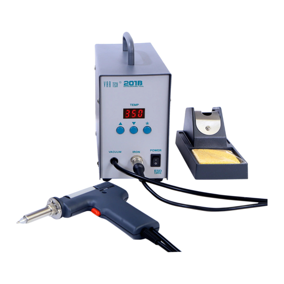
- Page 1 VECTECH 201 Desoldering Tool Instruction Manual...
- Page 2 Thank you for purchasing this desoldering tool. Please read manual carefully before using. Store this manual in a safe, easily accessible place for future reference.
-
Page 3: Specification
VECTECH 201 Ⅰ、Specification In this instruction manual,WARNING and CAUTION are defined as follows WARNING: Misuse may potentially cause death of, or serious injury to the user. CAUTION: Misuse may potentially cause injury to the user or physical damage to the objects involved. - Page 4 VECTECH 201 Receptacle Connect with the cord assembly. LED Display Display the setup temperature LED Heater Display Lamp Tie-in Connect with filter. TEMP Control Button Set and control temperature VACUUM IRON POWER Power Switch When turned to ON, the heating element starts to heat up.
- Page 5 VECTECH 201 CAUTION : Before setting, please check whether the voltage accords with the rated voltage on the unit’s nameplate. 1. Iron Holder and Sponge CAUTION: The sponge is compressed. It will swell when moistened with water. Water and squeeze it dry. Failure to do so may result in damage to the nozzle.
-
Page 6: Set The Temperature
VECTEVH 201 The heater lamp flickers when the temperature has stabilized. CAUTION: After turning the power switch to ON, wait 3 minutes before beginning desoldering operations. 3. Set the Temperature CAUTION: Always set the temperature to as low as possible for the work being done. - Page 7 VECTECH 201 Using the “▲”or“▼”button will change displayed value as shown below. 1234567890 Press the “*” button. The right (the 1’s digit) will then begin flashing to indicate that the 1’s digit can be set. 4. Select the desired value for the 1’s digit.
-
Page 8: Set Parameters
VECTECH 201 relay the set temperature about 2 seconds. If within 2 seconds, press the“▼”knob again, the setting temperature will drop 1℃ again. If press the“▼”knob and not loose at least 1 second, the setting temperature will drop rapidly. Till the needed temperature reaches, then loose the“▼”knob. -
Page 9: Working Mode
VECTECH 201 7. When display window is showing Input New Password press ”*” button, and shows , It indicates the unit comes into inputting new password state. Pressing“▲”or“▼”button will change displayed value. See “ set temperature normally” 8. When three digits press”*”... -
Page 10: Calibrate Temperature
VECTECH 201 Please refer to the “Working Mode Table” for the meaning of the digit displayed. Note: “X” represents the original working mode digit. Warning: The heater and soldering tips will be seriously oxidized or damaged when working with a high temperature. - Page 11 VECTECH 201 Method of recalibrating temperature: Use the thermometer to calibrate , and it is precise comparatively. Calibrate by using thermometer 1. Set the unit’s temperature to a certain value. 2. When the temperature stabilizes, measure the nozzle’s temperature with thermometer and write down the reading.
- Page 12 VECTECH 201 CAUTION: Never leave any solder remaining inside the hole in the P.W.B. Problems during desoldering If solder remains, resolder the component and repeat the desoldering process. Clean the tip of the nozzle Keep the solder-plated section of the nozzle a shiny white by coating it with a small amount of solder.
- Page 13 VECTECH 201 2. Replacing the Filter Pipe Replace the filter pipe as shown step ①~③. During operation, the filter pipe is very hot. Wait until the filter pipe is cool before replacing the filter. We recommend keeping a second filter pipe containing new filters handy, and replacing the installed filter pipe with this backup filter pipe.
- Page 14 VECTECH 201 qualified person in order to avoid personal injury or damage to the unit. 1. The solder in the junction is not sufficiently melted • Temperature is not high enough. The following parts require a greater heat capacity to desolder.
-
Page 15: Heater Error
VECTECH 201 Check the connections and replace any worn parts. ? ·Is the nozzle or hole in the heating element clogged Clean it. 6.The nozzle does not heat up. ? ·Is the desoldering gun cord assembly properly connected Reconnect it ?... - Page 16 VECTECH 201 2. Servicing the Desoldering Gun CAUTION The desoldering gun will be extremely hot. During maintenance, Please wear gloves and work carefully. ① Inspect and clean the nozzle. ·Plug in the power cord, turn the power switch On and let the nozzle heat up.
- Page 17 VECTECH 201 ② Disassemble the heating element Remove the nut with the heat resistant pad. Heating Element Element Cover Nozzle ③ Clean out the hole in the heating element with the provided cleaning pin. CAUTION: Be sure the solder in the hole in the heating element is completely heated. Before cleaning the hole.
-
Page 18: Maintenance (Station)
VECTECH 201 Ceramic Paper Filter(S) Attach the front holder to the filter pipe so that it does not leak air. Firmly press the back holder assembly into the filter pipe in order to properly seat the O-ring against the pipe. -
Page 19: Replacing The Heating Element
VECTECH 201 • Disassemble the pump heads Disassemble the rear panel and remove the cover, take out the pump head from each side of the pump. • Clean the pump head Remove the valve plate and fixing plate and clear any flux adhering to the plates. - Page 20 VECTECH 201 ⑤ Recalibrate the temperature. The resistance of new heating element varies, resulting in variations in operating temperatures. It is necessary to recalibrate the temperature every time the heating element is replaced. (See the Calibrate temperature) Remove the filter pipe...
- Page 21 VECTECH 201 Ⅸ、Replaceable Parts Parts List (Desoldering Gun)
- Page 22 VECTECH 201 Item No. Part No. Part Name Description 45001 Front Holder Without Front Holder & Spring Filter 14001 Spring Filter Ceramic Paper Filter(S) 47044 (Assembly) 47001 Filter Pipe With Front Holder & Spring Filter 26099 O-ring 47002 Back Holder Assembly...
Need help?
Do you have a question about the 201 and is the answer not in the manual?
Questions and answers