Table of Contents
Advertisement
Advertisement
Table of Contents

Subscribe to Our Youtube Channel
Summary of Contents for NWI NTS03
- Page 1 OWNER'S MANUAL NTS03 TOTAL STATION...
- Page 2 User Safety WARNING: Carefully read the Safety Instructions and Product Manual before using this product. The person responsible for the instrument must ensure that all users understand and adhere to these instructions. FCC Compliance This device complies with part 15 of the FCC Rules. Operation is subject to the following two conditions: (1) This device may not cause harmful interference, and (2) this device must accept any interference received, including interference that may cause undesired operation.
-
Page 3: Table Of Contents
Content 1. Use of instrument ............6 2. Names and functions of the components ..... 9 2.1 Names of the components ..........9 2.2 The information of the displays ........11 2.3 Functional keys under the basic measurement mode .. 15 2.3.1 Angle mode (including three pages) .... - Page 4 3.13 Selecting Data File ............ 25 4. Preparations before measurements ...... 26 4.1 Unpacking and storing instruments ......26 4.2 Set up the instrument ........... 26 4.2.1 Using plummets to center and level (align) ..26 4.2.2 Using centering device to center ...... 27 4.3 Loading and unloading of battery .......
- Page 5 8.1 Offset (Angle) ............. 43 8.2 Offset (Dist1) ............... 44 8.3 Offset (Dist2) ............... 45 8.4 Offset (Plane) .............. 46 8.5 Offset (Column) ............47 9. Menu ................50 9.1 Surveying ..............50 9.1.1 Operation ............50 9.1.2 Preparation ............51 9.1.3 Station and backsight ........
- Page 6 9.4.1.1 ―Input T.H‖ Mode ......... 77 9.4.1.2 ―Without T.H‖ ..........78 9.4.2 Resection ............79 9.4.3 MLM ..............79 9.4.4 Coord.Z ............80 9.4.5 Area measurement ..........82 9.4.6 Projection ............83 9.4.7 Roadway ............84 9.5 Options ................ 84 9.6 Adjust ................
- Page 7 11.4 The Perpendicularity of Collimation axis and Cross axis (2C) .................. 101 11.5 Vertical plate index zero automatic compensation .. 102 11.6 Vertical index error (angle i) and set vertical index 0 ....................102 11.7 Centering device ............103 11.8 Addictive constant (K) ..........104 11.9 The parallelism of collimation axis and photoelectricity axis ..............
-
Page 8: Use Of Instrument
Standard Warranty Terms Warranty period for NTS03 is 36 months from date of purchase. NWI warrants this instrument made by Northwest Instrument to be free from manufacturing defects in materials and workmanship. For... - Page 9 Northwest and the defect must be proven to NWI‘s satisfaction. At the time that it is proven to the NWI‘s satisfaction that the instrument is defective, it shall be repaired or replaced, at the NWI‘s option and returned to the original purchaser at no cost to...
- Page 10 Other remedies may or may not be available for transportation damages. These designs, figures and specifications of NTS03 are subject to change without notice. NWI shall not be held liable for damages resulting from errors in this instruction manual.
-
Page 11: Names And Functions Of The Components
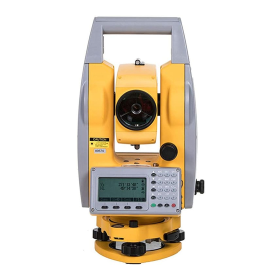
2. Names and functions of the components 2.1 Names of the components Handle Coarse sighting device Objective lens Vertical clamping and tangent screw Plate level Display keys serial port SD card port connector Base... - Page 12 Battery Focusing knob Horizontal eyepiece axis center Horizontal clamping and tangent screw Base Leveling screw...
-
Page 13: The Information Of The Displays
2.2 The information of the displays Symbols on the keyboard Keys Name Function In the basic interface,enter the angle Angle measurement . Under other modes, move measurement the cursor up or up to select the options. In the basic interface,enter the distance Distance mode DIST... - Page 14 The characters at the bottom line of the F1~F4 Soft Keys display indicate the meaning of the soft keys. Input numbers or characters or choose the Number keys menu In any measurement interface, you can enter the star key interface .You can set the ★...
- Page 15 Slope distance. dSD is to stake out differences between slope distances. Northing. dN is to stake out differences between north-coordinates. Easting. dE is to stake out differences between East-coordinates. Elevation. dZ is to stake out differences between Z-coordinates EDM(Electronic Distance Measurement) is in progress. Unit in meters (metric units) Units in feet Units in American feet...
- Page 16 View List out details of the current record Info. Displays the name, code and coordinate of the current station and back-sight station. Settings Set the height of the instrument and the target Enter coordinates of the station where instrument is placed.
-
Page 17: Functional Keys Under The Basic Measurement Mode
2.3 Functional keys under the basic measurement mode 2.3.1 Angle mode (including three pages) 278°12′23″ 278°12′23″ [F4] 159°54′05″ 159°54′05″ Save 0set Hset Hold [F4] 278°12′23″ [F4] 159°54′05″ H-Bz Vmode Page Soft key Reference Function Record the measured angle to the Save selected file. -
Page 18: Distance Measurement Mode
Switch between HR (horizontal right/ clockwise) and HL (horizontal left/ anticlockwise) mode Vertical Angle Mode (altitude angle(Vh), Zenith(Vz) Display the first page of the soft key functions. The key [★] is used to set contrast, light, compensator and parameters of distance measurement . It can work under the basic modes. -
Page 19: Coordinate Measurement Mode
2.3.3 Coordinate measurement mode 278°12 23 278°12 23 159°54 05 159°54 05 [F4] 278°12 23 [F4] 159°54 05 [F4] Page Soft key Reference Function Start coordinate measurement and record Save the measured data into the selected files (measurement file ‗File(.MEA)‘ or coordinate file ‗File(.COO)‘... -
Page 20: Explanation Of Saving Data
2.3.4 Explanation of saving data If you have never selected the measurement file and your first time to use the [Save] soft key, a dialogue box of ‗Select file‘ would appear to the screen. Mention that this is a good chance for you to select all files that the instrument may use. - Page 21 pressure, and view the signal. (The setting of the distance measurement. After you input the temperature and pressure, pressing [F1] can automatically calculate the value of PPM, if you are not satisfied with the value, you can input and save it). The interface of picture as shown below: Temp.: 1013 Press:...
-
Page 22: Initial Setup
3. Initial setup 3.1 On & Off Press the power key until the screen displays pictures. The instrument is now switched on. After self-checking, the instrument enters Angle Mode automatically (see Angle Mode for details) Pressing power key will leads to a dialogue box. Press [ENT] to turn off the instrument. -
Page 23: Signal
appear as followed. Temp.: 1013 Press: Prism c: PPM: Signal: 3.5 Signal The function of signal is to display the intensity of signal of EDM (Electrical Distance Measurement). It can help achieve ideal aiming result under poor conditions. If it is too difficult to be found, using signal can easily aim at the target. -
Page 24: Set Up The Atmospheric Correction Value (Ppm) Directly
The standard atmospheric value of our series Total Station (i.e. the atmospheric conditions when the correction is zero) Atm: 1013 Pa Temp:20℃ The calculation of atmospheric correction △S= 277.825- 0.29434P/(1+0.003661T) (ppm) In the formula: △S: correction coefficient (unit: ppm) P: atmospheric pressure (unit: hPa) T: temperature (unit:℃) 3.6.1 Set up the Atmospheric Correction value (ppm) directly You may measure the temperature and pressure to find out the... -
Page 25: The Correction Of The Atmospheric Refraction And The Earth Curvature
3.7 The Correction of the Atmospheric refraction and the Earth Curvature When measuring horizontal distance and elevation, our instrument corrects the atmospheric refraction and the earth curvature automatically. The formulas of two corrections about our instrument are as followed: Corrected Horizontal Distance : D=S×[cosα+sinα×S×cosα(K-2) / 2Re] Corrected Elevation : H=S×[sinα+cosα×S×cosα(1-K) / 2Re]... -
Page 26: Setup Of Automatic Shutdown
Miniread(dist) [ 0.001 0.0001 3.10 Setup of Automatic Shutdown Refer to the operation ―Menu→5.Options→3.Other options→2. Auto shut off”. The interface as shown in picture below: Auto shut off [ 1. Never 5minutes 10minutes 10minutes Exit Enter You may choose ‗Never‘ to cancel the auto shutdown. When choosing 5, 10, 20 minutes opts, the instrument will shut down automatically if there is no key pressed. -
Page 27: Selecting Data File
constant after strict measurement (e.g. in standardization site for baseline being measured by authenticated units). 3.13 Selecting Data File The instrument needs large data and creates large data when it is operated. This data needs to be storied in the system files of the instrument as a file form. -
Page 28: Preparations Before Measurements
4. Preparations before measurements 4.1 Unpacking and storing instruments Unpacking Lay down the box gently with the top side facing up. Open the lock and take out the instrument. Storage Cover the telescope cover. Make sure that the vertical clamping screw and the level bubble face upwards. -
Page 29: Using Centering Device To Center
Screw C buble center Screw B Screw A Using the plate level to level the instrument precisely ① Loosen the horizontal locking screw and turn the instrument around until the plate level is perpendicular to a line shaped with screws A and B. Adjust the screws A and B to make the bubble in the center of the level;... -
Page 30: Loading And Unloading Of Battery
center and that the top is leveled. Screw up the three locking screw; ② Make sure that the center of the tripod top is right above the station; ③ Stamp one foot on the ground with your feet. Install the instrument gently on the top of the tripod and screw up the screw connection. -
Page 31: Reflecting Prism
temperature range. ▲A battery can be recharged for 300-500 times. ▲A monthly recharging is required if the instrument is not used for a long time. 4.4 Reflecting Prism. When measuring distance with prism mode, a reflecting prism must be set at the target site. You can connect the prism to the base, and then connect the base onto the tripod .you can also set the prism onto the centering rod. - Page 32 numbers. ● Input letters Example 1: Entering to the interface of selecting file in the surveying, which needs to input ―SUN1A‖ in the edit box Press [Num.] to switch to the mode of inputting letters. Select file(.MEA&.COO) Select file(.MEA&.COO) File: File:...
- Page 33 Select file(.MEA&.COO) File: SUN1A List Alph. Enter ● Input numbers Example 2: Take surying mode for example in the menu, Select file (.MEA&.COO) and press [Enter], Inputting the station and press [STA] and [F3],which needs to input ―-123.456‖ in the edit box. Because the edit box ―NO‖...
-
Page 34: Notice For Using U Disk
The order of the keys:[1]→[2]→[3]→[·]→[4]→[5]→[5]→[6]; The result is as shown below: Set HA 123.4556 Exit Enter Clear After completing the input, press [F4] to confirm the input or press [ESC] to cancel it. If it is over ―360°‖, a prompt box will appear ―Overtop!‖. -
Page 35: Angle Mode
5. Angle mode The instrument would enter the Angle Mode automatically after switched on. You can also enter this Mode by pressing [ANG] under basic measurement mode. This Mode involves three pages switched by the key [F4]. Their functions are explained as followed: 278°12′23″... -
Page 36: 0Set
5.2 0set Function: set the horizontal angle as 0 °00′00″. ● Press [F2](0set); Asking ―Set 0?‖, press [ENT] to set 0 or [ESC] to exit this ● operation. In order to make sure the accuracy, you may press [ENT] lightly. 5.3 Hset Function: Set the horizontal angle as wanted angle. -
Page 37: Angle By Repetition
5.5 Angle by repetition Function: Under right horizontal angle mode, you can measure angle repeatedly. 3rd meas.starts 3rd meas. End(avg. of 3 meas. Is displayed 2nd meas.starts 2nd meas. End(avg. of 3 meas. Is displayed 1st meas.starts 1st meas.starts( angle between two points is displayed) ●... -
Page 38: Slope (V%)
Count 120°20′00″ 120°20′00″ 120°20′00″ Oset Exit Rel. Aim at point ‗A‘ again by horizontal motion and tangent ● screw and press [F3](Rel.); Count [ 1] 120°20′00″ 120°20′00″ 120°09′30″ Oset Exit Hold Aim at point ‗B‘ again by horizontal motion and tangent ●... -
Page 39: L/R
5.8 L/R Press [F2] to make the horizontal angle mode switched between right angle (HR) and left angle (HL). HR: Right angle mode .When the alidade is rotated clockwise, the horizon angle is increscent; HL: Left angle mode. When the alidade is rotated anticlockwise, the horizon angle is decreasing. -
Page 40: Distance Mode
6. Distance mode Press [DIST] to enter the distance measurement mode, which has two interfaces . The functions of first interface are ―Save‖, ―Meas.‖ and ―Mode‖; The functions of the second interface are ―Offset‖, ―S.O‖ and ―m/f/i‖. The two interfaces shown as below: 278°12 23 278°12 23 159°54 05... -
Page 41: Offset
Press [▲] or [▼] to move the ―[]‖ the wanted option , then press [ENT] to save. 6.4 Offset Press [Offset] to enter the interface of offset (will described in the offset function). 6.5 Stake out (S.O) Enter the distance stakeout function DistStakeout HD:... -
Page 42: Coordinate Mode
7. Coordinate mode Press [CORD] to enter the coordinate measurement mode. According to the diagram below, please set up the coordinates station, azimuth, target height and instrument height before coordinate measurement. Center of lens Center of instrument Coordinates of unknown point (N1,B1,Z1) Coordinates of the center of instrument =NC,BC,ZC+... - Page 43 ―Information‖ appears after pressing [Yes] (if you haven‘t select measured file, there will be a interface of ―Select file (.MEA)‖ to let you select file.), which needs you the point name (Pt.N) ,Code and target height (T.H). The number of ―Pt.N‖...
- Page 44 avoid repeated operation, please first operate the function of ‗STA‘ (‗Station‘) then set the BSS and orient. When orientation, please aim at the BS (target) precisely. Orientation can be done with [0set], [Hset] and [Hold] under Angle Mode. If the orientation is already done under Angle Mode, you don‘t need to set BSS again under Coordinate Mode.
-
Page 45: Offset Mode
8. Offset mode ―Offset(Angle)‖, includes five functions which ―Offset(Dist1)‖,―Offset(Dist2)‖,―Offset(Plane)‖,―Offset(Column)‖. These functions help for coordinate measurement, and can get the coordinates of the point which the prism can‘t be at. Before operating these functions, please set ‗STA‘, orientation, instrument height and target height. -
Page 46: Offset (Dist1)
Press [Meas] to start measurement. After measuring, press [Enter] to enter the interface of ―Offset (angle)-Result‖: Offset(Angle)-Result 200°54′21″ SD: 11.775 HD: 11.773 VD: 0.190 Next P Save Then, aim at offset point, you can get its coordinates. Pressing [Next P] to measure next point; press [Save] to save the coordinates of offset point;... -
Page 47: Offset (Dist2)
angle offset. After input the known distance, press [ENT] to enter the interface of ―Offset (dist1)-Prism‖ : Offset (dist1)-Prism HR: 200°54′21″ SD: HD: VD: Mode Meas After measuring, press [Enter] to enter the result interface: Offset (dist1)-Result HR: 200°54′21″ N: -10.998 E:... -
Page 48: Offset (Plane)
Offset (Dist2) Distance: Clear Enter Input the distance, and press [Enter] to enter the interface of ―Offset -Begin‖. You must aim at point ―P0‖ to measure.After measuring, press [ENT] to exit the interface to enter the interface of ―Offset-End‖. Offset-Begin Offset-End 171°49′54″... -
Page 49: Offset (Column)
P1(with Prism) (with prism) (with prism) (without prism) In the menu of ―Offset‖, select ―4. Offset (Plane)‖ to enter the interface of ―Offset –Pt.1‖: Offset (plane)-Pt.1 200°54′21″ Meas Mode Press [Meas] to measure point 1, and press [Enter] to receive the measured data and enter to the interface of ―Offset (plane)-Pt.2‖. - Page 50 ‗P1‘ on the cylinder under this mode. Then calculate the horizontal distance, azimuth angle and coordinate of the cylinder by measuring the surface points of tangency P2 and P3. The average value of P2 and P3 is the azimuth angle of the cylinder.
- Page 51 Press [Enter] → Offset (Column)-R.edge HR: 181° 26′16″ SD: 4.570 HD: 4.575 VD: 1.004 Enter After aim at the left edge, press [Enter] to enter the interface of ―Offset (column)-L.edge‖. After aim at the right edge, press [Enter] to enter the interface of ―Offset (column)-Center‖, as shown in picture below: Offset(column)-Center 179°59′39″...
-
Page 52: Menu
9. Menu In the basic measurement interface, press [MENU] to enter the menu interface, then, press [F4] to enter the next page. Menu Menu 1.Adjust 1.Surveying 2.Stake 2.Config [F4] 3.Fileman 3.Select CodeFile 4.Grid scale 4.Program 5.Options 5.Communication On the every page of menu, you can press number key to select. For example, if you press [1], the first option ―1.Surveying‖... -
Page 53: Preparation
9.1.2 Preparation Firstly, you must select a file for surveying. When staring surveying, it appears a dialog for select file. Select file(.MEA&.COO) File: Press [F2] (List) to enter the interface of ―Select Disk‖. If you have inserted the SDdisk, it would be displayed. Select Disk [FLASH Exit... -
Page 54: Example For Set Station
mode and coordinate measurement mode is common. You can input or change the station point or orientation angle. The two methods of setting station are as followed: 1) Set station by using the data in memory; 2) Input directly by keyboard; Three methods of the orientation angle of backsight point are followed: 1) Set backsight point by coordinate in memory;... - Page 55 Set STA 100.000 100.000 10.000 > Enter? 5) The system checks the current coordinate file,if checks it ,then display the coordinates and you can press [F4] (Yes) to confirm the coordinates of station and exit to the interface of ―Setup STA‖; Setup STA STA->...
-
Page 56: Example For Setting Angle
9) Press [F3] (Save) with the station coordinates displayed; Setup STA 100.000 100.000 10.000 > Enter? 10) Press [F4](Yes) to finish setting station; 9.1.3.2 Example for setting angle The azimuth angle must be confirmed by measuring. You can save the data of orientation angle of backsight point by the following method. - Page 57 Setup BBS NBS: 100.000 EBS: 100.000 ZBS: 10.000 > Enter? 5) The system checks the current coordinate file, if checks it ,then display the coordinates and you can press [F4]; Setup BSS BBS-> Code: 1.000 I.H: Input Search Meas 6) Input ―Code‖ and target height ―T.H‖; Setup BSS BBS: Code->...
-
Page 58: 4Measurement
current settings will be saved in the measurement file; 9.1.4Measurement 1) In the first page of surveying, press [3] to enter the interface of ―Meas‖; Surveying Meas 1.Station Pt.n-> 2.Setup BSS Code: 3.Meas 1.000 m T.H: 4.Survey Config 2) Press [F1](Input) to input the measurement point name ,then press [Enter] to input code;... -
Page 59: Staking Out
90°12′22″ 200°54′24″ [Sgnl]<< >Measuring... 6) After finishing measuring, press [F4](Yes) with data saved; 90°12′22″ 200°54′24″ 17.245 17.125 -1.523 >Enter? 7) The point name will be added one, and you can measure next point. You can input name ,code and target height as the same way and measure as the same way of last point by pressing [F4](Ditto) or you can press [F3] to select the measurement methods;... -
Page 60: Staking Out Points
Menu Select Stake-out File 1.Surveying 2.Stake File: 3.Fileman 4.Program 5.Options List Num. Enter The Menu of staking out is as followed: 1.Setup STA 1.PolarCoord.Meas [F4] 2. Setup BBS 2.Resection 3. Stake out The ‗Setup STA‘ and ‗Setup BSS‘ are the preparation work for staking out. - Page 61 Stake out -1.015 -3.311 0.320 > Enter? 4) Input the target height; 5) After setting the stake-out point, you can start to stake out. Stake out-Calc HR: 252°23′52″ HD: 3.473 m Coord. Dist HR:The calculated angle of tak-outpoint HD: the calculated distance from instrument to stake-out point; Aim at the prism center, then press [F1](Dist) (or [F2](Coord.)) 6) The rotation angle of the alidade will be calculated by the instrument;...
-
Page 62: Polar Coordinates
252°23′52″ 252°23′52″ 0°00′00″ 0°00′00″ dHR: dHR: [Sngl]<< [Sngl]<< dHD: Meas Mode Next P Meas Mode Next P [Dist] [Coord.] HD: Measured distance dHD: Distance difference when aiming at stake-out point dN: measured coordinate(N)- coordinate (N) stake-out dE: measured coordinate(E)- coordinate (E) stake-out dZ: measured coordinate(Z)- coordinate (Z) stake-out 8) When the values of ―dHR‖, ―dHD‖... - Page 63 1.PolarCoord.Meas 2) Input the new point name, code and target height; PolarCoord.Meas Pt.n: Code: 1.000 T.H-> Meas 3) Aim at mew point, and press [F4] (Meas) to start measurement; PolarCoord.Meas 252°24′22″ [Sngl]<< Measuring... 4) After measuring, the measured coordinates is displayed. You can press [F4](Yes) to save the measured value, and the point name will be added 1;...
-
Page 64: Resection
9.2.3 Resection Set up instrument on a new point, and measure at most 5 known points to calculate the coordinates of this new point, the measurement of resection is as following: ●Resection by distance measurement:Measure at least two known points. ●Resection by angle measurement:... - Page 65 can press [F3](Coord.) to input coordinates, then press [F4] to confirm; Resection No.1 9.169 7.521 12.215 m Clear Pt.n Enter [Enter]→ Resection No.1 9.169 7.521 12.215 > Enter? 5) Press [F4](Yes) to enter the interface of ―Input T.H‖. After input the target height (T.H) , press [F4]; Input T.H T.H:...
- Page 66 Resection NO.2 Pt.n: List Num. Enter 9) According to step 5)~step 8), when using [Dist] to measure, the residual will be calculated. Resection Resid. -0.003 dHD = 0.001 m Next P Calc 10) Press [F1] to measure other known points, which are at most five points;...
-
Page 67: File Manager
13) Press [F4] (Coord.) to view the coordinates of the new points. Otherwise, the coordinates will be saved in the coordinate file and as station coordinates. Coord. 12.322 34.622 1.577 >Save? 9.3File manager The menu of file manager is as follows: Fileman Fileman 1.File Dialogbox... - Page 68 all files in the system and can press [▲][▼][◄][►] to select file. 444.COO [COO] 111.LSH [LSH] [MEA] TEST.MEA [COD] 1111.COD 11123.LSV [LSV] Info Search Notice: COO—coordinate file COD—Code file MEA— Measurement file LSH—Horizontal alignment file for road stake-out LSV—Vertical alignment file for road stake-out Operations for files: 1) View the file information Press [Info.] to view the selected file,as shown in picture below.
- Page 69 1. New File(.MEA) 2. New File(.COO) 3. New File(.COD) 4. New File(.LSH) 5. New File(.LSV) Press [1] → New File(.MEA) File: Num. Enter 4) Delete file After selecting a file, press [DEL] to enter the interface of ―Del‖, as shown in picture below. Press [ENT] to delete file and press [Exit] to cancel to delete file and back to file list interface.
-
Page 70: Import
STA:ST1 Code:tree N:328.263 E:656.365 Z:1.236 Edit First Last Turn Press [Edit] to enter the interface of ―Information‖, and you can just edit point name (Pt.n), code (Code).and target height (T.H)(Notice: can‘t edit the data of station and backsight), then back to the last interface; ... - Page 71 transfer software must be installed on the PC to end data, or the instrument can‘ receive. Press [Fileman]→ [2](Import)→ [1.Import from PC],then the interface of ―Import data‖ as shown below: Import data 1. Receive (.COO) 2. Receive (.COD) AS an example of receiving coordinate data, press [1] to enter the interface of ―Select file(.COO)‖;...
-
Page 72: Import From Usb
9.3.2.2 Import from USB Firstly, you must insert the Udisk to instrument. The instrument will read the text files (.TXT) in the ‗PROJECT‘ folder in the Udisk. You must make sure that the imported files must be in the ‗PROJECT‘ file, and the file name must be letters, numbers or together. -
Page 73: Export
Select the coordinate format matched coordinate file, such as ,if the file ―SUA.TXT‖ selected is saved according to the ―Pt,N,E,Z,Po‖, you can press [1] to enter to the next interface; Input new filename File: SUA.COO Num. Enter The filename extension of imported file will be changed as ―.coo‖... -
Page 74: Export To Usb
Select file(.MEA) File: 1.MEA List Num. Enter After selecting the measured file, press [Enter] or [ENT] to enter the interface of ―Select format‖. The format of “Sunway” that the transmission software our instrument equipped can receive and analysis. But the format of “SSS” means the format of Topcon (GTS-7), which you can’t use the t transmission software our instrument equipped to receive. -
Page 75: Export With Mini Usb Port
Export data 1. Send (.MEA) 2. Send (.COO) 2) AS an example of measurement data, press [1] to enter to the next interface, as shown in picture below. Input the measurement file which needs to be exported or press [F2] to retrieve; Select file(.MEA) File: 1.MEA... -
Page 76: Format Disk
Clear Enter 1) Input ―PIN‖ (Contact NWI for update PIN), then press [ENT] with the instrument shutdown; 2) Connect the instrument to the computer through serial port connector. Open the hyper terminal softwareand set up the correct port. - Page 77 3) Press power button on the instrument. The page of hyper terminal is as followed; Note: you must be specifically cautious when updating. As soon as you choose to update, the instrument will enter updating mode. If pressing key ‗3‘ under the page shown below, the previous program may be resumed.
-
Page 78: Program
5) Select the new version of total station software and click ‗ Send ‘ on the computer; 6) Then the computer displays the process of sending. After finishing updating, display the operation menu again .You can press [5] to update boot image and press [6] to update language;... -
Page 79: Remote Height (Rem)
Menu Select file(.COO) 1.Surveying 2.Stake File: 3.Fileman 4.Program 5.Options List Num. Enter enter into the program menu, as shown in picture below: P r o g r a m P r o g r a m 1.Project 1.R E M 2.Resection [F4] 2.R o a d w a y... -
Page 80: Without T.h
REM-Prism 77°18′33″ 169°11′14″ Meas Mode Enter Aim at prism, then press [Meas] to measure the horizontal distance between target point and instrument. Press [Enter] to enter the interface of ―REM-Ground to target‖; REM-Ground to target 77°18′33″ 169°11′14″ 0.000 m Then, turn the telescope up and down to aim at the target point. The VD column displays the elevation difference from the ground to the target point. -
Page 81: Resection
Aim at the reference point and press [Select] to enter the dialog of ‗REM-Altitude‘ REM-Altitude 77°18′33″ 169°11′14″ 0.000 m SetVA Then turn the telescope up and down. The elevation difference between the target and the reference point is displayed in the VD column. -
Page 82: Coord.z
target. You may also input the coordinate or retrieve coordinate from files to calculate the value. There are two modes of ‗MLM‘: 1.MLM (A-B,A-C): measure A-B, A-C, A-D…. i.e the starting point is the reference point of all following points. 2.MLM (A-B, B-C): measure A-B, B-C, C-D…. - Page 83 Coord. Z Setup STA Pt.n: Input List Coord. Enter Here, you can press [Coord.] to input station point, or press [List] to retrieve coordinate from known files. 2) Setup datum mark. You can press [2] (Datum mark) to enter the interface of ―Coord.Z-No.1‖; Coord.Z-No.1 >Pt.n:...
-
Page 84: Area Measurement
[Set A] to set the backsight angle, and you can press [ESC] to exit thus function. 9.4.5 Area measurement This function is to help you to calculate out the area of the plane figure formed by measured or inputted coordinates. 1) Press [MENU]→[4](Program) →[4](Area) to enter the interface of area measurement‘;... -
Page 85: Projection
measured coordinate is inserted below the indicator column, which determines the shape of the formed area. The area enclosed is the connection of line from start to end one by one in order. Thus, you may not get the correct area, if the graphic of area has crossed line. You may press [★] key to check the shape of the area. -
Page 86: Roadway
In the interface of ―Setup Baseline‖, press [1](Meas) to enter the interface of ―Project(Begin)‖,as shown in picture below: Project(Begin) 50°02′17″ 175°13′13″ Meas Mode Enter Press [Meas] to start measuring, then press [Enter] to enter the interface of ―Project(End)‖; Project(End) 55°53′34″ 164°21′45″... - Page 87 Options 1. Unit options 2. Mode options 3. Other options Press [1] to enter the interface of ―options‖ Unit options Unit options 1.Type of feet 1.Unit(Temp.) 2.Unit (Angle) 2.Unit(Press) 3.Unit (Length) Press [2] to enter the interface of ―Mode options‖: Mode options 1.EDM Mode 2.NEZ option...
-
Page 88: Adjust
9.6 Adjust Warning: The following functions must be carried out under the guidance of professionals, if the operation is wrong, it may lead to the instrument can’t work properly! Press [MENU]→[F4] →[1](Adjust) to enter the interface of ―Adjust‖: Adjust 1. Calibrate I.E 2. - Page 89 Enter the interface of tilt calibration: 90°00′00″ Tilt X= 125 F1 Up 3′ Enter Specific steps are as follows: 1) After leveling the instrument, aim at the target F1 in the collimator face left, record the current vertical angle as V0. 2) Set the vertical angle to ‗V0+3′‘with the help of the vertical tangent screw.
-
Page 90: Calibrate Tilt:y
Note: CoK (linear coefficient): If absolute value > 1.5, you need to re-calibrate; In the correction process by pressing the ESC key, will exit, holding compensator parameters unchanged. 9.6.3 Calibrate TILT:Y Enter the interface of tilt calibration: 90°00′00″ Tilt Y= 75 F1 Up 3′... -
Page 91: Config (Instrument Constant)
Note: CoK (linear coefficient): If absolute value > 1.5, you need to re-calibrate; In the correction process by pressing the ESC key, will exit, holding compensator parameters unchanged. 9.7 Config (Instrument constant) Operations are permitted only when the instrument was tested strictly. -
Page 92: Communication
Scale factor:the measurement station scale factor 3) Grid scale factor of coordinate Grid scale factor of coordinate=Altitude factor × Scale factor Distance calculation: 1) Grid scale distance(HDg)= HD× Grid scale factor HD= distance on the ground 2) Distance on the ground(HD)= HDg/Grid scale factor Grid scale 悬高测量-棱镜点... -
Page 93: Roadway
10. Roadway Roadway function is divided into two parts: Design Roadway and Stake out Roadway. You may stake out designed points according to the stake and deviation of the Designed Roadway. Select ―[Menu]→4.Program→[F4](P2)→Select file (.MEA&.COO) and press [Enter]→1.Roadway‖ to enter the interface of road menu: Roadway Roadway... - Page 94 interface of ―Define(H)-Begin‖, then you can select the other lie type to input. After finishing the input, press [ENT] to enter the interface of ―List of H curve‖; Define(H)-Begin Mark: Clear Enter Note: Do not define the length as ‗0‘, which indicates ending the alignment.
-
Page 95: Intersection Method
Define(H)-Spiral Len.: Clear Enter The ―R‖(Radius) indicates the radius of end point of spiral transition curve; After inputting the ―Line‖, ―Circle‖, ―Spiral‖, press [ENT] to receive the input and exit to ―Define(H)‖. if you want to view the input, press [ENT] to finishing inputting and enter the interface of ―List of H curve‖;... -
Page 96: Vertical Alignment
Point PT Para A1 Para A2 Radius R Former point Next point ‗PT‘ is the intersection point of road. The ―x‖ of ―Px‖ is the number of intersection point. When inputting R,A1, and A2, they can‘t be negative. If inputting the radius, the system will insert an arc with defined radius in between the former point and the next point. -
Page 97: Stake Out (Road)
Stake 508.306 1000.48 Altitude 324.325 329.247 325.689 Length 84.56 52.806 In the ―Roadway‖ menu, select ―Re-define (V)‖ to enter the interface of ―Define (V)-Begin‖: Define(V)-Begin Mark: Height: Len.: Clear Enter After inputting the ―Mark‖, ―Height‖ and ―Len.‖ (Length), press [Enter] to confirm, and enter the interface of the point 01 input, as hown in picture below: Define(V)-01 Mark:... -
Page 98: Selecting Roadway File
time for the demand so that staking out roadway with any mileage can be done easily. You may not be worried about the problem that the capacity of 20 point of horizontal alignment and 20 point of vertical alignment, because you can divide any long road into several pieces and save them into several line type files. -
Page 99: Setting Station And Bss(Backsight Point)
10.2.2 Setting station and BSS(backsight point) See reference in setup BSS and setup station 10.2.3 Stake out road Before staking out Roadway, please first enter the parameters required for staking out. e.g starting mileage, space between, ―L dist‖(left distance), ―R dist‖(right distance), ―L dV‖ and ―R dV‖. Parameter 1/2 Parameter 2/2 L dist:... - Page 100 Pt.n: 100.0 Code: 126595.622 N: 326532.868 E: 324.325 Z: Save Enter The ―Pt.n‖ indicates the mileage of the mark selected (which system accepts the maximum of is 8 characters).then you can press [Save] to save the information of staking out to the current coordinate file.
-
Page 101: Adjustments And Corrections
11. Adjustments and Corrections The instrument is under strict test and calibration, the quality is accord with the standard demand. But after a long-distance transportation and environment change, the small change of instrument parameter is inevitable. Therefore, the new purchased instruments should be checked and calibrated before surveying to ensure the precision. -
Page 102: Reticle Of The Telescope
11.3 Reticle of the telescope Check 1. Aim at a target A from the telescope after leveling the instrument the cross wire on the reticle. Lock the instrument with vertical and horizontal locking knob after aiming at A. 2. Rotate the vertical slow motion knob, move A point to the edge of the field of view (A 'points);... -
Page 103: The Perpendicularity Of Collimation Axis And Cross Axis (2C)
11.4 The Perpendicularity of Collimation axis and Cross axis (2C) Check 1. Set a target A in about 100m away, and make sure the vertical angle of the target is within ± 3° .Precisely level the instrument and switch on it; 2. -
Page 104: Vertical Plate Index Zero Automatic Compensation
11.5 Vertical plate index zero automatic compensation Checkout 1. After Setting up and leveling the instrument, make the direction of the telescope consistent with the line between the center of the instrument and any of the foot screw; 2. The vertical plate index change to zero after switching on Tighten the vertical brake hand-wheel and the instrument display the current telescope vertical Angle;... -
Page 105: Centering Device
i= (L+R-180° )/2 or Angle i= (L+R-540° )/2; 4. If | i |≥10", may be you need reset the zero value of vertical index; 5. For the following steps, see reference in chapter 11.6.1. Note: Repeat the checkout steps to retest the index error again (i Angle). -
Page 106: Addictive Constant (K)
Cross center on the ground 5. Repeat step 4, check and calibrate until it meet the requirements; 6. With the laser plummet, unbolt the laser cover, using 1 # hex wrench to adjust the three screws, fasten one side and loosen the other side, and adjust the laser flare to point O;... -
Page 107: The Parallelism Of Collimation Axis And Photoelectricity Axis
method above, and the original instrument constant is ‗-20‘, so the new value should be set as ‗-20-(5) =-15‘; Input ‗-15‘ through "menu-> 6->2" and then confirm. Use the vertical line of the reticle to orientate, make A, B and C at the same line accurately. - Page 108 it 5 meters and 20 meters away. Start laser direction function. Focus on the reflector center by the telescope crosshair center, then check the position of the red laser point. Generally speaking, the telescope is equipped with special filter, human eyes can′t see laser point through the telescope, you can see the offset between the red laser point and the reflector crosshair center, you can observe this above the telescope or at the side face of reflector.
-
Page 109: Technical Parameters
12. Technical parameters Serial Function Unit NTS03R — Imaging Erect Magnification × — Telescope Field of view 1゜20′ Min.target distance Effective aperture 40/50(EDM) (″) 2C index error (″) Angle i index error Angle measurement Angle measurement — Absolute encoder (Hz, V) method (″) Minimum reading... - Page 110 and white screen) — Illumination Support Wavelength 635nm Laser (optional) Laser Maximum output power — Laser Plumb Plumb (adjustable): not less than 0.4 m W, not more than 1.0 mW (″)/2 Tubular level Level ( ′) /2 Round level — Built-in application Support Rechargeable High-energy...
-
Page 111: Appendix A File Format Introduction
Appendix A File format introduction These following examples to instruct exported file format ST001,1.205,AD 100.000,100.000,10.000 BS001,45.2526,50.0000 BS001,1.800 98.2354,90.2314,10.235 A1,1.800,CODE1 104.662,99.567,10.214 A2,1.800,CODE1 78.3628,92.4612,4.751 A3,1.800,CODE1 63.2349,89.2547 NOTE this note Every record consists of two lines: The information of first line: record type, name, elevation, code Such as: STA refers to station point BKB refers to back sight Angle data... -
Page 112: Appendix B Bi-Directional Communication
Appendix B Bi-directional communication The total station controlled by external computer can sent the information about angle and distance. The settings of communication and protocol as follow: ● Baud rate: 2400~115200 available ● Data length: 8 ●Stop bits: 0 ●Parity bits: none ●protocol: ●Code: STX(02),CR(13),X_ON(17),X_OFF(19) The angle ans diatance data are transferred by a form of fixed... - Page 113 ADDRESS: 69 King Street, Dover, NJ 07801, USA...
Need help?
Do you have a question about the NTS03 and is the answer not in the manual?
Questions and answers
Do you have to have a special program downloaded to the PC to download data? The instrument is a NTS 03 Total Station.