Table of Contents
Advertisement
Quick Links
Advertisement
Table of Contents

Related Manuals for OneFex CS-IO204


Summary of Contents for OneFex CS-IO204
-
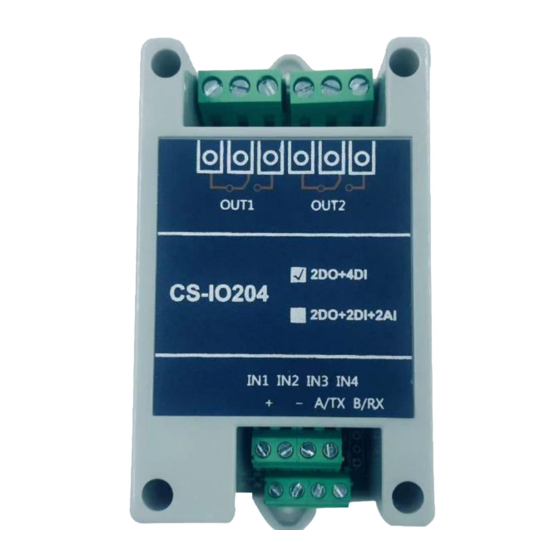
Page 1: Cs-Io204
CS-IO204 User Manual CS-IO204 Serial I/O Module Manual / 13... -
Page 2: Table Of Contents
CS-IO204 User Manual CS-IO204 ............................... 1 PRODUCT INTRODUCTION ......................5 ............................5 EATURES ............................5 ARAMETER ........................... 6 ELECTION ............................6 IMENSION WIRING INSTRUCTIONS ........................6 .......................... 6 ERMINAL EFINITION ........................7 OMMUNICATION IRING 2.2.1 RS485 Wiring ........................7 DO W ............................ - Page 3 CS-IO204 User Manual 5.2.4 Multiple devices on the 485 bus and ON/OFF operation failed to send the broadcast address 254..........................23 5.2.5 PLC and the device cannot communicate normally ............23 AFTER-SALE SERVICE ........................24 ............................. 24 OMMITMENT ............................24 ISCLAIMER UPDATE HISTORY ..........................
- Page 4 CS-IO204 User Manual Notice ❖ Please read this manual carefully before use and save it for reference. ❖ Please follow to the operating procedures and precautions in this manual. ❖ Please open the package carefully and check whether the device and accessories have been damaged due to transportation when you receive the device.
-
Page 5: Product Introduction
CS-IO204 User Manual Product Introduction CS-IO series products are serial IO module using standard Modbus-RTU protocol, supporting RS485/232. Support wide voltage power supply, multi-channel input and output control, which can be widely used in various application scenarios such as industrial production, agriculture, smart city and office buildings. -
Page 6: Item Selection
CS-IO204 User Manual Flash ON Flash OFF All ON All OFF Functions NOLock Linkage Mode Local Self-locking Linkage Interlock Dual-machine Non-locking Linkage Dual-machine Self-locking Linkage Working mode change DO independent control Software support DI status query Overall DO control; Debugging information query;... -
Page 7: Communication Wiring
CS-IO204 User Manual Normally ON The 2 DO normally ON terminal Public The 2 DO public terminal Normally OFF The 2 DO normally ON terminal Normally ON The 1 DO normally ON terminal Public The 1 DO public terminal Normally OFF... -
Page 8: Low Load Wiring
CS-IO204 User Manual 2.3.1 Low Load Wiring Applicable for non-resistive load current< 3A or resistive load current < 5A 2.3.2 AC 220V Load Device Wiring / 13... -
Page 9: Ac 380V Load Device Wiring 【With Zero Line
CS-IO204 User Manual 2.3.3 AC 380V Load Device Wiring 【With Zero Line】 2.3.4 AC 380V Load Device Wiring【Without Zero Line】 / 13... -
Page 10: Digital Input Wiring
CS-IO204 User Manual Please add an AC contactor/intermediate relay between this device and the load in the following four cases: 1. Load rated voltage>30VDC 2. Load rated voltage>250VAC 3. Non-Resistive Load Current>3A 4. Resistive load current>5A 2.4 Digital Input Wiring Parameters and Working Mode Configuration 3.1 Device and PC Connection Settings... -
Page 11: Device Communication Address Reading
CS-IO204 User Manual (4) DIP address table: 3.2.2 Device Communication Address Reading After the device connected normally, the IO module debugging software read the current address 254 [only support broadcast read address when there is one device on the bus]. -
Page 12: Baud Rate Reading And Setting
CS-IO204 User Manual 3.2.4 Baud Rate Reading and Setting Click "Read" and "Set" to read and set the baud rate and address respectively, which will take effect immediately after the operation. 3.3 Working Mode 3.3.1 Normal Mode The DO takes corresponding actions after ON or OFF command. -
Page 13: Lock Linkage Mode
CS-IO204 User Manual operates the DO, it is linked by the optocoupler state before the DO is still in action. 3.3.3 Lock Linkage Mode In this mode, each time the optocoupler inputs a signal, the corresponding DO is flipped once. -
Page 14: 2Device Lock Linkage
CS-IO204 User Manual In this mode, if the 485 bus is used, multiple devices can be connected in parallel, and the addresses of the devices match each other, so that the remote switch value can be transmitted. For example, if there are multiple low-speed... -
Page 15: Development Data Instruction
CS-IO204 User Manual Development Data Instruction 4.1 Communication Protocol Instruction This product supports standard Modbus commands. For detailed command generation and parsing methods, you can refer to "MODBUS Protocol English Version" based on the register table in this article. This product supports Modbus RTU format. - Page 16 CS-IO204 User Manual Parameters Configuration Modbus Explaination Register Register address address Communication 03E8H 41001 See the below corresponding baud rate table of baud rate values, the default value is 0, and supports 0- 5. This register determines the Holding communication...
-
Page 17: Command List
CS-IO204 User Manual 16 15 14 13 12 11 10 9 The bit 8 of the data of register 30009 is the same as the data of register 00001. The same is true for the optocoupler input. Bit8 and bit9 of register 30003 and registers 10001 and 10002 all correspond to the specified hardware. -
Page 18: Query Do Status
CS-IO204 User Manual Field Meaning Note Device address It is the broadcast address 05 command Single control command 00 00 Address Register address of the DO to be controlled FF 00 Command DO OFF action CRC16 CRC16 checksum of the first 6 bytes of data 98 35 4.4.2 Query DO Status... -
Page 19: Flash On Flash Off Command
CS-IO204 User Manual Number of queries Number of optocoupler status to be queried 00 04 6D C6 CRC16 CRC16 checksum of the first 6 bytes of data Optocoupler return information: Return code: FE 02 01 00 91 9C Field Meaning... -
Page 20: All On And All Off Command
CS-IO204 User Manual Return code:FE 10 00 03 00 02 A5 C7 Field Meaning Note Device address 10 command Return instruction:If the query is wrong, return 0x82 Device address Query the address of the device 00 03 00 02 Number of commands... -
Page 21: Active Reporting Protocol
CS-IO204 User Manual Starting address 00 00 Quantity Number of DOs returning information 00 02 C0 05 CRC16 Check digit 4.4.6 Active Reporting Protocol This function is a non-standard Modbus protocol, which can only be used in dual- computer mode, and is suitable for the IO module to actively report changed switch value. -
Page 22: The Do Can Only Be Turned On But Not Turned Off
CS-IO204 User Manual addresses; Confirm whether the serial port number on the software is correct; Check whether the power supply and work indicator are normal; For the RS232 version, please correctly identify the RS232 serial port module used as male or female. - Page 23 CS-IO204 User Manual 5.2.4 Multiple devices on the 485 bus and ON/OFF operation failed to send the broadcast address 254. If there are multiple devices on the 485 bus, the address of each device cannot be the same, and the broadcast address 254 cannot be used for communication.
- Page 24 After-sale Service 6.1 Commitment OneFex provides after-sales service of the device within 2 years from the date of sale. But for damage caused by improper use, you need to send it back and take the freight for repair or adjust. Make sure that the package is in good condition to avoid damage during transportation.
Need help?
Do you have a question about the CS-IO204 and is the answer not in the manual?
Questions and answers