Table of Contents
Advertisement
Quick Links
Advertisement
Table of Contents

Subscribe to Our Youtube Channel
Related Manuals for Juntek MHS-5200A


Summary of Contents for Juntek MHS-5200A
- Page 2 Hangzhou Junce Instruments Co., Ltd. MHS5200 Series Function/Arbitrary Waveform Signal Generator User Manual Rev1.0 AUG 2020...
- Page 3 Copyright Hangzhou Junce Instruments Co., Ltd. all right reserved. Trademark Information JUNTEK is a registered trademark of Hangzhou Junce Instruments Co., Ltd. Notices JUNTEK products are covered by P.R.C. patents, issued and pending. This document replaces all previously published documentation.
-
Page 4: Safety Requirement
Do Not Operate With Suspected Failures If you suspect that any damage may occur to the instrument, have it inspected by JUNTEK authorized personnel before further operations. Any maintenance, adjustment or replacement especially to circuits or accessories must be performed by JUNTEK authorized personnel. -
Page 5: Notices
Hangzhou Junce Instruments Co., Ltd. Provide Adequate Ventilation Inadequate ventilation may cause an increase of temperature in the instrument, which would cause damage to the instrument. So please keep the instrument well ventilated and inspect the air outlet and the fan regularly. Do Not Operate in Wet Conditions To avoid short circuit inside the instrument or electric shock, never operate the instrument in a humid environment. -
Page 6: Table Of Contents
Hangzhou Junce Instruments Co., Ltd. Contents Guaranty and Declaration ................. I Safety Requirement ..................II General Safety Summary ................II Notices ..................... III Inspection ......................1 ChapterⅠ MHS5200A Signal Generator Overview ..........2 1.The Instrument Introduction ..............2 2.Model Description .................. 2 3.Instrument characteristics ..............2 4.Specifications ..................3 ChapterⅡ... -
Page 7: Inspection
We would not be responsible for free maintenance/rework or replacement of the instrument. Check the Contents Please check the contents according to the packing lists. If the instruments are damaged or incomplete, please contact your JUNTEK sales representative. Host MHS-5200A Series Dual Channel Signal Generator... -
Page 8: Chapterⅰ Mhs5200A Signal Generator Overview
Hangzhou Junce Instruments Co., Ltd. ChapterⅠ MHS5200A Signal Generator Overview 1.The Instrument Introduction The MHS-5200A series of instruments use large-scale FPGA integrated circuits and high-speed MCU microprocessors. The internal circuit adopts surface mount technology, which greatly improves the anti-interference and service life of the instrument. -
Page 9: Specifications
Hangzhou Junce Instruments Co., Ltd. With -120%~+120% DC bias function; Pulse wave duty cycle adjustment is accurate to 0.1%; With 4 TTL outputs with variable phase difference; It has the functions of frequency measurement, period measurement, positive and negative pulse width measurement, duty cycle measurement and counter;... - Page 10 Hangzhou Junce Instruments Co., Ltd. Frequency stability ±1X10 /5 hours Arbitrary / other waveform 50Ω±10% Amplitude characteristic Amplitude range (peak-to-peak value) 5mVp-p~20Vp-p Amplitude resolution 1mVp-p (-20db attenuation) 10mVp-p(No attenuation) Amplitude stability ±0.5%(Each 5 hours) Amplitude error ±1%+10mV(Frequency1KHz,15Vp-p) Offset range -120%~+120% Offset resolution Relative range 0~359°...
- Page 11 Hangzhou Junce Instruments Co., Ltd. Total harmonic distortion <0.8%(20Hz~20kHz) Rise and fall time ≤20ns Square wave Overshoot ≤10% Duty cycle adjustment range 0.1%-99.9% Output level ≥3Vpp TTL signal Fan-out coefficient ≥20TTL Rise and fall time ≤20ns Low level <0.3V COMS signal High level 1V~10V Rise and fall time...
- Page 12 Hangzhou Junce Instruments Co., Ltd. Input voltage range 0.5V-pp~20Vp-p Counting range 0~4294967295 Counting method Manual Positive and negative pulse width 10ns resolution, maximum measurement 10s measurement Period measurement 20ns resolution, maximum measurement 20s Duty cycle measurement 0.1% resolution, measuring range 0.1% ~ 99.9% 1.
-
Page 13: Chapterⅱ Instrument Introduction
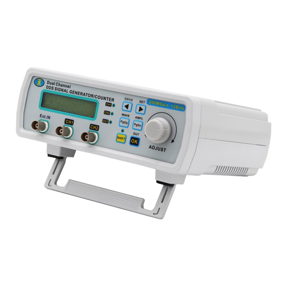
Hangzhou Junce Instruments Co., Ltd. ChapterⅡ Instrument Introduction 1.Front Panel Overview Panel introduction video:https://youtu.be/flecFKTi9v8 Figure 2-1-1 MHS5200A front panel diagram Table 2-1-1 MHS5200A front panel diagram illustration Label Illustration Label Illustration Ext.In input port Status Indicator CH1 output port Operation keys CH2 output port Shuttle knob 2.Rear Panel Overview... -
Page 14: Function Area Description
Hangzhou Junce Instruments Co., Ltd. Figure 2-2-1 MHS5200A rear panel diagram Table 2-2-1 MHS5200A rear panel diagram illustration Label Illustration Label Illustration DC5V power input interface TTL input/output interface USB communication interface Power switch 3.Function area description The liquid crystal display of the instrument is divided into 2 functional areas, as shown in Figure 2-2, and the description of each part is shown in Table 2-2. -
Page 15: Menu Function Description
Hangzhou Junce Instruments Co., Ltd. Confirm key Channel switching (CH1/CH2) Switch the function position, adjust the frequency when ”*” sign is in the first line, and adjust the function option when "*" sign is in the second line Press this combination keys to quickly enter the waveform adjustment interface Press this combination keys to quickly enter the amplitude adjustment interface... -
Page 16: Chapterⅲ Basic Operations Of The Instrument
Hangzhou Junce Instruments Co., Ltd. BURST:OFF It means that the burst function is on or off Ext.IN means analog signal input port, TTL.IN means digital signal MSR-SEL:Ext.IN input port Measurement mode,FREQ means measure frequency;COUNTR means counter function; POS-PW means MSR-MODE:FREQ. measure the positive pulse width;... - Page 17 Hangzhou Junce Instruments Co., Ltd. This section will introduce how to operate the instrument in detail. It should be noted that the CH2 channel of this instrument is similar to the CH1 channel. When the green light corresponding to the CH1 is on, it means that the current operation is the parameter of the CH1 channel.
- Page 18 Hangzhou Junce Instruments Co., Ltd. Figure 2-3-1 05.00V in the picture refers to the peak-to-peak value.In this mode of amplitude setting function, the maximum amplitude is 20V, the minimum value is 0.20V, and the minimum step value is 0.01 (10mV). As shown in Figure 2-3-2, press the key 【OUT/OK】...
- Page 19 Hangzhou Junce Instruments Co., Ltd. 【 SHIFT+SET/► 】 to switch the sign “*” to the second line, press the key 【CH1/2/◀ 】or 【SET/►】can move the cursor, and then rotate the “Adjust” knob to adjust the phase parameters as shown in Figure 2-6-1. It should be noted that the phase difference is only meaningful when the CH1 frequency and the CH2 frequency are the same after tracking function is turned on.
- Page 20 Hangzhou Junce Instruments Co., Ltd. Select Ext.IN port for inputting AC signals, and TTL.IN port for inputting digital signals. In the main interface, press the key 【 WAVE/PgUp 】 or 【AMPL/PgDn】 to enter the input port selection interface as shown in figure 2-9-1, then press the keys【SHIFT+SET/►】...
- Page 21 Hangzhou Junce Instruments Co., Ltd. Figure 2-10-2 (11) Frequency sweep function Setting the sweep function video: https://youtu.be/fDPzLjO4H-0 In the main interface, press the key【WAVE/PgUp】or 【AMPL/PgDn】to enter the initial frequency setting interface of the sweep function, and then adjust the initial frequency to 5kHz as an example as shown in Figure 2-11-1 below: Figure 2-11-1 ...
- Page 22 Hangzhou Junce Instruments Co., Ltd. Figure 2-11-5 (12) Save/Load function Set the store/modulation function video: https://youtu.be/pGs_o0EaBJo Save function: In the main interface ,press the key 【 WAVE/PgUp 】 or 【AMPL/PgDn】to enter the parameter saving interface, and then press the keys 【SHIFT+SET/►】 to switch the sign ”*” to the second line as shown in the Figure 2-12-1.
-
Page 23: Pc Software Control Output
Hangzhou Junce Instruments Co., Ltd. Figure 2-13-2 (14) Burst function Setting the burst function video: https://youtu.be/qns4jBj5jnU This function can realize the CH2 channel burst the CH1 channel output. The premise of the realization of the burst function is that the setting waveform frequency of the CH1 channel is greater than the CH2 channel. -
Page 24: Chapter Ⅳ For More Product Information
Chapter Ⅳ For More Product Information For more information about this instrument, refer to the relevant manuals by logging in to the official website of JUNTEK (www.junteks.com) to download them. "MHS5200A Operation Demo Video" provides operation video of this product.
Need help?
Do you have a question about the MHS-5200A and is the answer not in the manual?
Questions and answers