
Subscribe to Our Youtube Channel
Related Manuals for AERA AZURE 300


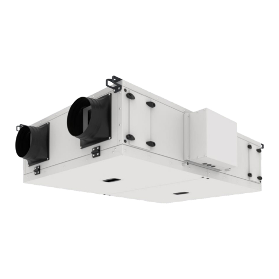
Summary of Contents for AERA AZURE 300
- Page 1 INSTALLATION AND OPERATING INSTRUCTIONS AZURE COUNTER FLOW HEAT RECOVERY VENTILATION...
- Page 2 Receipt The delivery contains one of the following unit types: MODEL ORDER NO MODEL ORDER NO AZURE 300 AZURE 1400 AZURE 500 AZURE 2200 AZURE 700 AZURE 3200 Please check delivery immediately on receipt for accuracy and damage. If damaged, please notify carrier immediately. In case of delayed notification, any possible claim may be void 1.4.
-
Page 3: Installation
1.8. Performance data Mechanical connections must be made correctly in order to obtain maximum efficiency from the device. The device's thermal efficiency, sound level and electrical performance may vary depending on the ambient conditions the device is operating. These conditions may affect the measurement result on site and vary from the catalogue data. 1.9. - Page 4 2.1. Ceiling installation Make sure the ceiling and fixing components can carry the device before installing The AZURE compact device. Unsuitable mounting material can lead to the unit falling uncontrollably from the ceiling. Different methods of protection should be used to prevent damage to devices due to the model.
-
Page 5: Functional Description
2.3. Flange connection/ adapter pieces Flange connections are recommended for Azure compact units are below MODEL Description Order No AZURE 300 AZURE 500 AZURE 700 AZURE 1400 AZURE 2200 AZURE 3200 Flange connections must be leakproof and firm. 2.4. Installation unit If installed in heated rooms and higher humidity, condensation can occur on the outside of the unit in the outside and extract air area. - Page 6 3.1. Functional diagram Name Item no. Outside air sensor Exhaust air sensor Extract air sensor Supply air sensor Adapter Controller Panel Frost protection sensor 3.2. Functions 3.2.0. Pre-heater and deicing The pre-heater, which is standard on the azure devices, comes after outside air F7 filtration. This application is to ensure that the heat recovery exchanger is protected from freezing in very cold weather.
- Page 7 Condition II: T-EHA is lower than +0 °C. Condition III: Preheater is not disabled. If all conditions are met, the preheater will be switched on and controlled according to T-EHA. PID-modulator values must be configurable. Step II: Reducing the flow rate / EHA and SUP air fan Condition I: Preheater has been switched on for longer than 3 minutes (100% power).
- Page 8 For this reason, the right sensor type connected to each analog input must be selectable. CO2 sensor can be done in E-Tool or on the HMI. VOD enabling/disabling Enabling/disabling of VOD mode by the user/installer (factory setting: deactivated) Scaling for different sensor types Linear function adjustment for sensors is possible in the scaling menu.
- Page 9 After 0-24 h of standby it runs again in VOD mode if there is a sensor signal The stopping time (0…24 h) is selectable by the installer. The VOD stop function can be disabled, when the stopping time is set to 0.
- Page 10 Position Explanation Alarm button: Gives access to the alarm list. Alarm LED: Indicates alarm by flashing red light. Write LED: Indicates by flashing yellow light that parameters can be set or changed. OK button: Press this button to be able to change or set parameters whenever possible. Also used to move between changeable parameters in one dialogue window frame.
- Page 11 4.1.1.1.1. Selected functions In these menus, you can see how some of the most important functions have been configured. Changes cannot be made. Heater, exchanger and cooling type. If one of the functions is not used, it will be shown as ”Not used”. This function is used during the summer to cool the building night-time using cool outdoor air, thereby reducing the need for cooling during the day and saving energy.
- Page 12 4.1.1.5. Digital inputs/ outputs This menu shows if the digital inputs and outputs are On or Off. 4.1.2. Temperature Here you can view all actual and setpoint values for temperature control. The menu is visible to all users, regardless of log on level.
- Page 13 4.1.2.3. Setpoint Cascaded room temperature control In control mode Supply air control/Room control, the setpoint is used when cascade connected room control is active. Submenu for setting the min and max limitation temperatures for the supply air. If two room sensors have been configured, you will also get this menu. The controller uses the average temperature of the two sensors.
- Page 14 Minimum run time is settable 0 to 720 minutes (FS= 20 minutes). 4.1.2.7. Frost protection temperature Relevant value for the water temperature at the frost protection sensor. Frost protection can be set to function either on Y1, Y4 or on both. The function only supports a single sensor.
- Page 15 4.1.3. Air control This menu is only shown if frequency controlled fans have been configured. Depending on the choice of fan control, different combinations of the menus below will be shown. 4.1.3.1. Pressure control SAF (there are also corresponding menus for EAF) Here, Actual and Setpoint values are displayed.
- Page 16 Submenu Setpoint values for normal speed (1/1) and reduced speed (1/2). The setpoint is set in % of the full output. 100 % = 10 V output signal. Submenu outdoor compensation. An outdoor temperature dependent compensation of the pressure setpoint value can be added. The compensation can be set for either the supply air fan alone or for both fans.
- Page 17 4.1.3.6. In applications with varying occupancy, the fan speed can be controlled by the air quality as measured by a CO2 sensor. CO2 can be set to function either on Y2, Y4 or both. 4.1.4. Time Setting 4.1.4.1. General This menu is only shown if humidity control has been configured. Corrigo has a year-base clock function.
- Page 18 4.1.4.5. Extended running Digital inputs can be used to force the unit to start although the timer says the running mode should be “Off”. For 2-speed fans and pressure/flow controlled fans, inputs for normal speed and reduced speed can normally be used. The unit will run for the set time.
- Page 19 If the access level is Operator, Service or Admin, the user will automatically be logged off to Normal after a settable time of inactivity. The time is settable. 4.1.5.3. Change password You can only change the password for access levels lower or equal to the presently active level.
-
Page 20: Dimensions (Mm)
DIMENSIONS & CHARACTERISTIC CURVES 5.0. Dimensions DIMENSIONS (mm) MODEL 1300 1338 160 X 160 1300 1338 200 X 200 1500 1055 1530 150 X 300 1400 1550 1355 1588 1295 250 X 500 2200 1850 1675 1888 1615 300 X 500 3200 2125 1950... - Page 21 5.1. Characteristic curves 5.1.1. Air performance Curves AZURE-300 AIR PERFORMANCE CURVE AZURE-500 AIR PERFORMANCE CURVE ECO DESIGN 2018 WORKING AREA ECO DESIGN 2018 WORKING AREA ECO DESIGN 2016 WORKING AREA Curves are presented at conditions where air density is Curves are presented at conditions where air density is measured 1,2 kg/m measured 1,2 kg/m AZURE-700 AIR PERFORMANCE CURVE...
- Page 22 5.1.2. Efficiency Curves AZURE-300 EFFICIENCY CURVE AZURE-500 EFFICIENCY CURVE EFFICIENCY EFFICIENCY % 100 % 100 % 97 % 97 % 94 % 94 % 91 % 91 % 88 % 88 % 85 % 85 % 82 % 82 % 79 % 79 % 76 % 76...
-
Page 23: Service And Maintenance
SERVICE AND MAINTENANCE Make sure that the power connection is disconnected before doing any work on the device. Danger of electric shock; moving parts (fan) and hot surfaces. Maintenance and service work must be performed by a minimum of 2 authorized personnel. Do not forget that the heat recovery device is heavy’... - Page 24 Unscrew the screws of the device service doors III. Remove the service door completely Remove filter from slides Be careful to air flow direction when installing the filter back into iii) The Azure compact unit is equipped with fine filters on the outside and extract airside as standard (pursuant to DIN EN 13779) It is recommended that filters be checked every six months for degree of soiling (danger of mould formation) and, if necessary, cleaned.
- Page 25 6.3. Service and maintenance of pre-electrical heater Make sure that the power connection is disconnected before doing any work on the device. Danger of electric shock; moving parts (fan) and hot surfaces. Unscrew the screws of the device service doors. Open device service covers (There may be water in the drain pan, be careful!) Unplug the electrical connections on the electric heater III.
- Page 26 Press down reset lever. III. Close the service doors and reconnect ventilation unit to power supply. Manual reset: 90 Automatically reset: 70 6.5. Terminal box with isolator/main switch The terminal box that is connected to the side of the casing ensures free access to the electronic component.
- Page 27 Wiring Diagram (the diagrams are going to be revised later.)
- Page 32 Spare parts Order No: Sparer Part’ Name Exhaust Air Fan Assembly Fresh Air Fan Assembly Main PCB Air Temperature Sensor (PT1000) Surface Temperature Sensor (PT1000) Heat Exchanger Heat Exchanger - Fixing sheet metal By-pass Actuator Main Transformer Contactor Presigo PCB Presigo PCB - CAP version TTC Triac Controller Fuse...
Need help?
Do you have a question about the AZURE 300 and is the answer not in the manual?
Questions and answers