Table of Contents
Advertisement
Quick Links
310 AirSense
Infrared CO
Installation & Operation of the
AMC-310 AirSense Infrared CO
IMPORTANT:
Please read these installation and operating instructions completely
and carefully before starting.
filename:
Manual_amc310_infrared CO2 analyzer.doc
215 Colonnade Road South, Nepean, Ontario, Canada K2E 7K3
Tel: (613) 225-9531 • Fax: (613) 225-6965 • Canada & U.S. Toll Free: 1-800-465-5777
E-mail: gas@armstrongmonitoring.com • Internet: www.armstrongmonitoring.com/gas/
INSTRUCTIONS
The Armstrong Monitoring Corporation
Analyzer
2
Analyzer
2
Copyright ©, Sept 2001, AMC
Revised, 7/16/2004
Advertisement
Table of Contents

Related Manuals for Armstrong Monitoring Corporation AMC-310

Summary of Contents for Armstrong Monitoring Corporation AMC-310
- Page 1 310 AirSense Infrared CO Analyzer INSTRUCTIONS Installation & Operation of the AMC-310 AirSense Infrared CO Analyzer IMPORTANT: Please read these installation and operating instructions completely and carefully before starting. filename: Revised, 7/16/2004 Manual_amc310_infrared CO2 analyzer.doc Copyright ©, Sept 2001, AMC...
-
Page 3: Table Of Contents
AMC-310 AirSense Infrared CO Analyzer TABLE OF CONTENTS Section Title Page WARRANTY......................3 LIABILITY......................3 MODIFICATIONS AND SUBSTITUTIONS............3 PRODUCT RETURN ..................3 PRODUCT INFORMATION..................4 ANALYZER ......................4 FACTORY CALIBRATION ................. 4 PRODUCT DESCRIPTION ..................5 GENERAL DESCRIPTION................. 5 3.1.1... - Page 4 AMC-310 AirSense Infrared CO Analyzer NOTE This page intentionally left blank...
-
Page 5: Warranty
18 months from date of shipment. During the warranty period, The Armstrong Monitoring Corporation will repair or replace components that prove to be defective in the opinion of AMC. We are not liable for auxiliary interfaced equipment, or consequential damage. -
Page 6: Product Information
AMC-310 AirSense Infrared CO Analyzer 2 PRODUCT INFORMATION 2.1 ANALYZER Analyzer Unit Order Number ………………..………………..Analyzer Part Number …………………..……………..….……. Analyzer Serial Number ….……………..…………..…….……. Sensor Part Number …………………………..………….…….. Sensor Serial Number ………………………..………….……… Power Supply Requirement ………………..……………….….. 20 – 28 VAC or 18 – 30 VDC Power Consumption ………………………………….…………. -
Page 7: Product Description
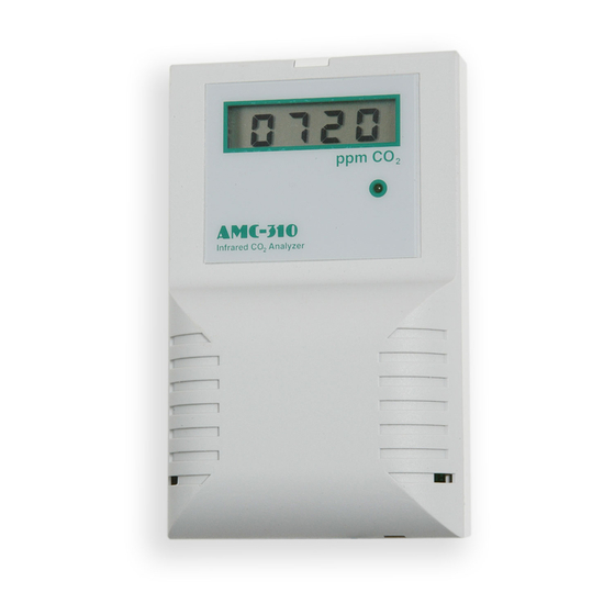
3 PRODUCT DESCRIPTION 3.1 GENERAL DESCRIPTION The AMC-310 AirSense is a non-dispersive infrared analyzer for measuring environmental CO concentration in ventilation systems and indoor living spaces. Its measurement range of 0 – 5000 ppm (parts per million; 1000 ppm = 0.1%) covers the range required to monitor compliance with ASHRAE or other ventilation efficiency standards. -
Page 8: Displays And Indicators
AMC-310 AirSense Infrared CO Analyzer 3.2 Displays and Indicators The basic Model 310 has a single green LED on the front panel which illuminates whenever the unit is operating. This LED is on steadily when the measured concentration is below the high limit, and blinks whenever the concentration is above the limit. -
Page 9: Installation
AMC-310 AirSense Infrared CO Analyzer 4 Installation 4.1 Cover Removal To open the Model 310 use a coin in the slot on the bottom to release the snap. Lift the cover up slightly to disengage the closure and remove cover with a downward motion to clear the catch at the top of the unit. -
Page 10: Wiring
AMC-310 AirSense Infrared CO Analyzer 4.3 Wiring This section describes the external connections to the Model 310. Wiring enters the chassis through the cutout in the center of the unit. 4.3.1 Power Supply The Model 310 will operate from an AC or DC input voltage between the values called out in the specifications on page 4. -
Page 11: Signal Output
AMC-310 AirSense Infrared CO Analyzer 4.3.2 Signal Output The Model 310 provides either a 0 – 10 volt or a 4 – 20 mA current loop output at the two terminals of the analog output connector shown in Figure 2. -
Page 12: Cover Replacement
AMC-310 AirSense Infrared CO Analyzer 3. Remove the shorting block from JP4 and restore it to its original position at jumper JP5. The Model 310 will reset and it’s output now corresponds to the actual detected CO concentration. 4.5 Cover Replacement Engage the top center of the cover under the latch at the top of the base, then press the bottom of the cover onto the base until it latches. -
Page 13: Field Adjustments
AMC-310 AirSense Infrared CO Analyzer 5 Field Adjustments This section describes the features that can be field configured and the procedures to make these changes. 5.1 Analog Output Range Adjustment This section refers to advanced features of the Model 310. -
Page 14: Altitude Correction
AMC-310 AirSense Infrared CO Analyzer 7. Use the ‘UP’ and ‘DOWN’ buttons to adjust the high output threshold to the desired value. In the example this would be set to 1000. 8. Remove the shorting block from JP4 and restore it to its original position at jumper JP5. -
Page 15: Calibration
AMC-310 AirSense Infrared CO Analyzer 6 Calibration This section describes the calibration verification procedure and calibration adjustment procedures. 6.1 Verification Procedure A quick but approximate calibration verification can be done by supplying the unit with outside air and letting the reading stabilize. CO concentrations in outside air are typically between 350 and 450 ppm. -
Page 16: Optional High Limit Contact
AMC-310 AirSense Infrared CO Analyzer display this setting can be adjusted by using a meter connected to the output. In this calibration mode the analog output is 10,000 ppm at full scale (i.e. 10.0 volts or 20.0 mA). If the voltage output is selected, this scaling corresponds to 1ppm per millivolt or 1 volt per 1000 ppm. -
Page 17: Duct Sampling Option
AMC-310 AirSense Infrared CO Analyzer 7 Duct Sampling Option 7.1 Overview The duct sampling option is used to divert a portion of the duct airflow through the Model 310. The difference between the total pressure at the upstream sample port and the static pressure at the downstream return port propels the sample stream. -
Page 18: Duct Kit Installation
AMC-310 AirSense Infrared CO Analyzer 7.2 Duct Kit Installation 1. Select a point along the duct where the probe assembly can be installed into unrestricted airflow without interfering with any internal duct components such as dampers, radiators, etc. 2. Mark and drill the four holes for the duct probe as shown in Figure 4. The centerline must be parallel to the air flow through the duct.
Need help?
Do you have a question about the AMC-310 and is the answer not in the manual?
Questions and answers