Table of Contents
Advertisement
Quick Links
Gavita
Master Controller EL3
™
1
Introduction
Thank you for purchasing the Gavita
the product. Mounting and installation of the Master Controller EL3 may only be executed by certified service personnel.
Please read and understand this manual completely before using the product. Only use the product as specified in this manual.
Failure to follow any of these directions for use and/or maintenance for this device will void any warranty on the product and
the owner will be fully liable for any damages.
1.1
Used Symbols
Warning! A warning indicates severe damage to the user and/or product may occur when a procedure is not carried
out as described.
Caution! A caution sign indicates problems may occur if a procedure is not carried out as described. It may also serve
as a reminder to the user.
Note: A note gives additional information, e.g. for a procedure.
This symbol is an internationally recognized symbol used to designate recyclable materials.
This symbol is an authorized use mark employed on electronic products manufactured or sold in the United States,
which indicates that the electromagnetic emissions from the device have been measured to be under the limits
published by the Federal Communications Commission. The FCC logo is a mark that declares that the equipment is
authorized to market and operate under the FCC's SDOC procedure.
This symbol shows that a product has been independently tested and certified to meet recognized standards for safety.
This symbol on material, accessories or packaging indicates that this product may not be discarded as household
waste. By properly disposing the equipment, you will be helping to prevent possible risks to the environment and public
health, which might otherwise be caused by improper handling of the discarded equipment. Recycling of materials
contributes to the conservation of natural resources. Therefore, please do not dispose of old electronics and electrical
appliances via household waste.
This symbol indicates the minimum distance (B) between the LED fixture (A) and the lit surface.
2
Product description
The Gavita Master Controller EL3 is a lighting controller with an 8" LCD touch screen display. Each controller can support up to
512 e-Series compatible fixtures on two channels.
The EL3 controller helps you control your lights to best suit your plants' growing needs. With this controller, you can program
on and off setpoints and build out complete growth schedules that allow you to automate your lights from early veg to late
flower. When using a compatible fixture (see Fixture Compatibility for reference), you can view their individual performance
at a granular level. It also lets you pick high-temperature dimming and shutdown setpoints to protect your plants if the room
temperature exceeds your desired level. An audible alarm can also be activated in the event that a setpoint is exceeded. The
EL3 can also utilize compatible Titan Controls™ sensors to gather additional environmental information.* A unique feature
of the EL3 is its data-logging capabilities, which allow you to look at your growing environment's historical metrics for
temperature, lighting cycles, humidity, CO
*This data is gathered when using compatible Titan Controls sensors only (sold separately).
Master Controller EL3. This manual describes mounting, installation and how to use
™
,* EC,* VWC, and substrate temperature.*
2
1
™
™
Advertisement
Table of Contents

Subscribe to Our Youtube Channel
Related Manuals for Gavita Master Controller EL3


Summary of Contents for Gavita Master Controller EL3
- Page 1 This symbol indicates the minimum distance (B) between the LED fixture (A) and the lit surface. Product description The Gavita Master Controller EL3 is a lighting controller with an 8" LCD touch screen display. Each controller can support up to 512 e-Series compatible fixtures on two channels.
-
Page 2: Product Information And Specifications
CAUTION – Changes or modifications not expressly approved by the party responsible for compliance could void the user's authority to operate the equipment. Contents (What’s included in the box) 1 x Gavita™ Master Controller EL3 1 mounting plate 7 x (expandable tube self-tapping screws) -
Page 3: Specification
EL3 Controller Dimensions ™ 238mm 33.6mm 33.6mm 250mm 12.2mm 21.4mm 12.2mm 21.4mm Connection Interface Introduction DC 15V 3A DC Power Adapter T-A Zone A Temperature Sensor Zone B Dimming Dry Contractor A&B Zone A Dimming 0-11.5V Input A&B Sensor Digital Sensor Debug Port ALARM Reset Key... -
Page 4: Safety Precautions
Doing so will void the warranty. Attention! Le contrôleur Gavita Master EL3 ne peut être utilisé que pour contrôler les ballasts compatibles de série électronique Gavita.Ne connectez pas le contrôleur à d'autres produits car cela peut être dangereux et peut causer des défaillances dans l'équipement connect é. - Page 5 ™ Cautions/Reminder Attention/Conseils Before using this product, please read all cautions and warnings. Avant d'utiliser ce produit, veuillez lire attentivement les conseils pertinentsLe contrôleur El3 appartient aux produits de précision de haute technologie, veuillez lire attentivement les conseils suivants. The EL3 features non-volatile memory, which will allow it to retain its settings and data in the event of a power loss. However, it does not have a backup battery to enable it to run when disconnected from power.
-
Page 6: Installation Of The Controller
512 luminaires in a single room. Warning! Only connect EL3 controllers to compatible fixtures. For an up-to-date list of compatible fixtures, visit gavita.com/EL3. Please note that when installing the temperature sensor and controller, hang the sensor at average canopy height between plants, preferably not against a wall. - Page 7 ™ Take the controller and carefully remove the mounting plate from the body. Use countersunk screws to secure the mounting plate to the wall Connect the luminaire cable to the controller...
- Page 8 ™ Connect the power adapter and temperature probe. The display will light up, and you can continue setting up the controller. Once all primary connections have been made, reconnect the controller to the wall mount bracket. (If using accessory output/inputs, i.e., Alarm, Sens or, External Control, or Contactors, make these connections prior to connecting controller to bracket.)
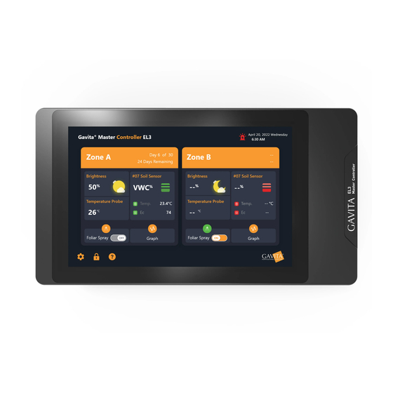
- Page 9 When the EL3 controller is powered on, the display will appear similar to the image below. At this point, you will see Zone A and Zone B, the current time, the Gavita logo, and the Settings button. Regional overview of Zone A and Zone B...
- Page 10 ™ 10.2 Device Settings Page Click the “Device Settings” button in the bottom right corner to enter the setup page. The settings page contains three sub-pages: Basic Settings, Data Transfer, and System Tools. 10.3 Basic Settings Time Setting 10.4 Time Setting: Click the time and scroll up and down in the pop-up box to select the current time. Click the “Confirm”...
-
Page 11: Screen Brightness
™ 10.5 Date Setting Date Setting: Select the current date in the calendar pop-up box. Click the “Confirm” button to save the date, or click “Cancel.” 10.6 Time Format Setting The default time format is 12 hours; click the slider to switch to 24 hours. 10.7 Screen Hibernation Adjust the screen’s sleep time to your desired setting. -
Page 12: Volume Control
™ 10.11 Volume Control Modify the buzzer volume for alarm events. When positioned to the far left, the buzzer will be deactivated. Unless deactivated, the alarm will sound until the cause has been fixed. 10.12 Data Transfer Import: Upload settings from another EL3 for quicker installation and setup when using multiple units. Export: Plugin the USB flash drive to export zone settings and growth plans to sync with other EL3s. -
Page 13: Software Updates
The user can update the EL3 to take advantage of new features and capabilities. These updates can be found on https:// gavita.com/EL3. Using the included USB drive, download and place the EL3 APK of the software to be upgraded in the EL3 directory of the USB drive. - Page 14 Click “Data Reset” to clear data and restore factory settings. 11.5 About Us This screen introduces Gavita's official website and provides a QR code that leads to the EL3 landing page. 11.6 Open Source License This screen lists the open source digital certificates used by the APK.
-
Page 15: Fixture List
Fixture types are divided into two categories: Intelligent Fixtures: Sun System RS1850, Gavita CT1930e, Gavita 2400e Legacy Fixtures: Gavita 900e, Gavita 1700e, Sun System HPS, Gavita HPS, and other (A user-defined option for fixtures that are not Gavita or Sun System branded. Use at own risk.) 11.9... -
Page 16: Sensor List
™ Sensor List Daisy-chain up to sixteen Titan Conrtols sensors (sold separately) from the sensor port. Sensors are assigned to Zone A by default but can be set to Zone B. Standard data displayed by the Substrate Sensor: EC, VWC, and substrate temperature Data displayed by the 3 in 1 - VPD Sensor: VPD, temperature, and humidity 1 Click on the tab for the 3 in 1 Sensor to go to the sensor’s Detailed Information page. - Page 17 ™ Zone Switching: When the sensor is in Zone A, click “OK,” and the sensor will switch to Zone B. When the sensor is in Zone B, click “OK,” and the sensor will switch to Zone A Sensor Locating: Click “OK,” and the indicator on the sensor will start flashing. Use it to confirm the physical location of the sensor.
- Page 18 ™ 12.1 Click on the tab for Substrate Sensors to go to the sensor details page. This page allows you to name the sensor, position it, locate it, switch the substrate calibration, and add it to the home page. Substrate switching: Switch soil sensor to substrate being used - CocoPro or Stonewool.
- Page 19 ™ 12.2 Lighting Schedule Set a new lighting schedule: After entering the strategy screen, click “Add Lighting Schedule.” 2) Set fixture strategy: • Enter the name of the fixture strategy. • Click the “Calendar” button to set the strategy start time. •...
- Page 20 ™ 12.3 Chart Data graphs showing current real-time date and historical data. This page shows the device and sensor history. • Click on the sensor list to select a temperature probe, VPD sensor, or substrate sensor. Click on the light to turn the light history display on or off.
- Page 21 ™ SETTINGS FUNCTION DESCRIPTION Alerts when the current temperature Low temperature alarm falls below the set temperature value. If the temperature rises above the set temperature value, the light brightness Dimming 50% automatically adjusts to 50% of the total power. Brightness is restored once the Sensor Alarm - Temperature temperature falls 2ºC below the set value.
- Page 22 ™ SETTINGS FUNCTION DESCRIPTION Positive action on the contactor in the current zone following the lighting Dry Contact Control Follow the lighting schedule schedule, i.e., if the lighting is on, the contactor is closed; if the lighting is off, the contactor is open. Features This depends on the external input voltage that the current contactor...
-
Page 23: External Control
™ Low temperature alarm: When the room temperature is lower than the value set by the user, a warning with an alert box and an alarm message will be added to the alarm log page. • 50% Brightness: When the indoor temperature is higher than the value set by the user, it will alert the user in the form of an alert box, add the alarm information to the alarm log page, and reduce the brightness of all current lamps to 50% to allow for cooling. -
Page 24: Troubleshooting
1-888-478-6544 or writing Hawthorne at: Hawthorne Hydroponics LLC, 3204 NW 38th Circle, Vancouver, WA 98660, Attn: Customer Service. Manufactured for Hawthorne Hydroponics LLC, a subsidiary of The Hawthorne Gardening Company, 3204 NW 38th Circle, Vancouver, WA 98660 HawthorneGC.com | Canada: HawthorneGC.ca | +1-360-883-8846 | info@gavita.com ©2022. World rights reserved. 220712aSD...
Need help?
Do you have a question about the Master Controller EL3 and is the answer not in the manual?
Questions and answers