Table of Contents
Advertisement
Advertisement
Table of Contents

Summary of Contents for Harmopool Hydrolyse EC20
-
Page 2: Table Of Contents
Extra : operational use and maintenance of the chlorinator specification ......23 Maintenance of the peristaltic pump................26 Warnings ..........................26 Problem solution for the small steering box ..............27 Assembled by: Swimming pool BVBA Industrial Road 9 3190 Boortmeerbeek Belgium www.harmopool.eu... -
Page 3: Incharge
Incharge This manual contains all necessary information for installation, troubleshooting and maintenance. Read the manual thoroughly before opening or using the unit. The manufacturer of this product will not be held responsible for any injury and/or damage to the product, if that is the result of improper installation or unnecessary/intended maintenance. -
Page 4: Specifications
Specifications ZBSXxxxx ZBSXxxxxxx ZBSXXxxxxP 50 m3 75m3 120m3 pH Control ZWMX2155 Chlorine regulation Peristaltic pump Swimming pool EC 20 20g/h connection Flow switch safety 50mm rubber Dimension plate 38 x 48 cm (2x) Display card Harmo pool ref ZWMX7010 Relay map Harmo pool ref ZWMX7011 Installation Installation items... - Page 5 ○ It is recommended to put the installation of the water treatment unit in bypass configuration. ○ Install the water treatment unit on a solid basis. ○ Always keep the product upright. If the product is tilted or laid on the side, the electrodes cannot measure correctly.
-
Page 6: Installation Of The Water Treatment Plate
Installation of the water treatment plate 1. Attach the water treatment unit to a solid wall. Fix both the lower and upper part of the plate. 2. Insert pH and chlorine electrodes into the electrode holders. Fix the nut with pliers or wrench to tighten the cap. - Page 7 5 Make the electrical connections in such a way that: The salt electrolysis and acid pump cannot work if the filter pump does not work. The salt electrolysis and acid pump can be switched off if the filter pump is working. Zoutelectrolyse filter pump safety fuse with timer...
-
Page 8: Set The Parameters Of The Control Unit
Set the parameters of the control unit 9 Calibrate the electrodes The following steps, you have calibrated the electrodes in no time: 1. Immerse the probes in the calibration fluids for pH (pH 7) and Redox (465-468 mV) and wait 5 minutes to balance before proceeding with the calibration process. 2. - Page 9 With a good calibration of Ph and Rx, the screens disappear automatically. After 2 minutes the screens will disappear and you can read the values from the screen. If the calibration is correct, the values are as follows: a. pH 7.0 +- 0,1 b.
- Page 10 Attention! With salt electrolysis you may not use the dosing modes Continuous and Proportional. Explanation of the dosing method Proportional With the "Proportional" dosing method, the controller runs continuously through a cycle: pH and chlorine content are measured and stored for 40 seconds (no dosing at this moment) The chlorine (if necessary) is dosed for 2 minutes The pH-min (if necessary) is dosed for 2 minutes...
- Page 11 When the voltage drops or a flow interruption occurs, the timer will be reset and its time will be completely expired again. This procedure runs if the set time. After the time has elapsed, the pH dosage and measurement will continue, but no more chlorine will be generated. At the next 24 hours the timer resumes its settings or set time.
- Page 12 -The unit will measure Ph and Rx (redox) for 40 seconds. This measurement will be stored in memory. If PH is set to -: If the Ph value is much higher than the setpoint (target value), the Ph dosing pump runs for 2 min.
- Page 13 11.6) Flow switch; no, yes Here you can enter if the installation is equipped with a Flow switch. If you enter YES, the unit assumes that a flow switch is active. In case of a water flow a contact will close. When the contact is closed, the dosing pumps Ph and salt electrolysis can function, when there is no flow, the contact is open and so the dosing pump and salt electrolysis will not function or will stop at a flow stop.
-
Page 14: Chlorine Control Via Rx: Set Up The Rx Set Point
13) Build in suction nipple Insert the Ph suction cap into the acid canister. It is recommended not to lower the suction cap to the bottom of the canister. If something would go wrong with the dosage, the whole can of acid will not be pumped into the pool. 14) Start installation Start the installation by switching on the electricity of the pump until the salt is dissolved... - Page 15 Free Chlorine ORP/mV vs pH 8,2 ppm 0,65 0,67 0,75 0,95 0,95...
-
Page 16: Specification Of Ph Addition
Specification of Ph addition The pH value is corrected with pH min. We recommend the use of 15% -30% sulfuric acid, the weaker the sulfuric acid and how accurate the pH dosage will work. In the exceptional case that the pH drops below 7.2, it is best to bring it back to zone 7.2- 7.6 by adding pH plus. -
Page 17: Connecting A Level Switch
Connecting a level switch Two level switches can be added to the unit, for devices produced in 2020 or later. On the circuit board with the display, the "WLH" and "WLL" connections are located at the bottom center and right. These are connected to the two contacts of the level switch. Connect connection WLH to the level switch in the acid drum, and the connection WLL to the level switch in the chlorine drum. - Page 18 Auto power on means a power failure occurs during operation and when power is restored, the system automatically turns on. Remembering the last operation setting means the state before a power failure, or the system setting before a system failure, including the acceleration status, the acceleration status timer is reset.
-
Page 19: Installation Instructions
Installation instructions 1. Make sure that the pipe used for the installation is the same size as the salt chlorinator. The nominal diameter of the chlorinator's connecting pipe is: 1.5" or 50 2. Make sure the tap for the chlorinator is closed before use. 3. -
Page 20: The Use Of The Chlorinator
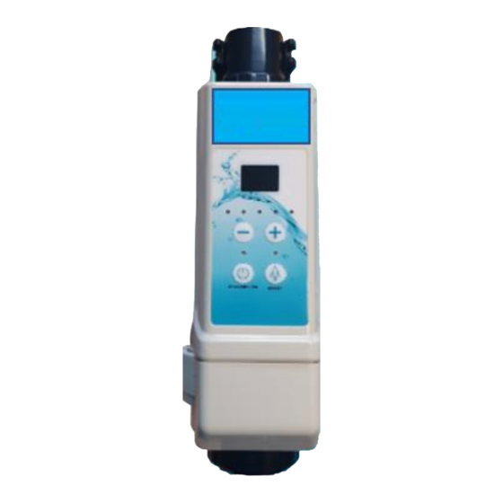
The use of the chlorinator 1. When the chlorinator is connected to the faucet, adjust the water flow with the valve to ensure there is enough water through the salt chlorinator. 2. To connect the power cord, open the decorative cover of the chlorinator in the direction indicated by the arrow on the cover. - Page 21 9. When the chlorinator reports a malfunction or warning, press the shift button. 1. Led monitor(shows the water temperature under normal operation, shows the corresponding error code when a problem occurs ) 2. level indicator light (1 light stands for level 1.2 light stands for level 2 ..
-
Page 22: Error Codes And Corresponding Chlorinator Solutions
Error codes and corresponding chlorinator solutions Code Reason for failure Remark Solution Coal fin Coal fin temperature is First check if the error code E6 is present, if temperature is too too high present , check if the temperature sensor is high connected , if connected replace the sensor ;... -
Page 23: Extra : Operational Use And Maintenance Of The Chlorinator Specification
Code Reason for failure Remark Solution The sensor in the the error must be check if the corresponding temperature controller is not working corrected manually sensor is attached, replace the sensor if this is properly the case water temperature the error must be first check if the corresponding temperature sensor defective corrected manually... - Page 24 1.2 The type of salt The purer the salt, the better the tide, the more economical the salt chlorinator. This also extends the lifespan of the chlorinator. The sodium chloride (NaCl) in the salt must be at least 99.6%. It is best if the salt is dehydrated granular sea salt of nutritional quality. Attention: a.
- Page 25 1.4 The correct way to add salt: A. Turn on the pool circulation pump and let the water circulation begin. B. Turn off the chlorinator. C. Test the current salt content of the pool. D. Calculate the amount of salt needed to add to the pool according to the corresponding formula.
-
Page 26: Maintenance Of The Peristaltic Pump
Maintenance of the peristaltic pump. The pump line has reached the end of its service life after 500/600 hours of operation (chemical compatibility) and must be replaced annually. The hoses of the inlet and outlet line must be replaced every two years. The nozzles should be descaled and rinsed every two years. -
Page 27: Problem Solution For The Small Steering Box
Problem solution for the small steering box PROBLEM CAUSE SOLUTION Screen does not light up No voltage present Verify voltage Acid pump does not dose Switch under the dosing pump Set switch to "1" is set to "O" Settings of pH control are wrong Verify settings : pH+ while pH- is dosed (or vice versa) - Page 28 Calibration failed Calibration fluid outdated or Replace calibration fluid dirty Probe not yet balanced Repeat calibration Probe broken Replace probe Probe left dry for a long time Leave probe in pool water for 24 hours, and recalibrate Device goes into alarm : pH too pH >...
- Page 29 A level detector is attached that Koppel niveaudetector gives incorrect contact A flow siwtch is connected and Verify flow and flow switch (go it indicates that there is no flow to setting flow switch : no) Acid pump continues to dosing Setpoint not yet reached No action required Wrong parameter set : pH+...
- Page 30 Liquid (acid or chlorine) in Santoprene dosing hose leak Check if dosing nipple is dosing compartment of chlorine clogged, and replace dosing or acid pump hose. Dosing hose in pH or chlorine Supply of acid or chlorine in Stop immediately aciding and dosing forms a bladder injection nipple stymied by dirt / clean/replace nipple.
- Page 31 LED8 flashes Too little salt in the water Add salt if necessary Te weing salt The salt is not dissolved Deposits or foreign objects Clean the cells cause flooding The electrolytic cell is worn Replace the cells Led9 flashes Too much salt in the water No action prepares or really too much, Too much salt diluting water...
Need help?
Do you have a question about the Hydrolyse EC20 and is the answer not in the manual?
Questions and answers