Table of Contents
Advertisement
Quick Links
Advertisement
Table of Contents

Summary of Contents for SAFE FLIGHT SCc Angle of Attack
-
Page 3: None Revision Notice
Dwg. 56201-2 PROPRIETARY NOTICE This document contains proprietary information and covers equipment in which Safe Flight has proprietary rights. No data contained herein may be duplicated, used, or disclosed, in whole or in part, for any purpose, without the express written permission of Safe Flight Instrument Corporation. -
Page 4: Table Of Contents
Page 4 of 28 Sym B Dwg. 56201-2 TABLE OF CONTENTS Para. Description Page None Title Page ........................1 None Revision Notice ......................2 None Proprietary Notice ......................3 None Table of Contents ......................4 System Description ....................... 5 SCc..........................5 System Components ..................... -
Page 5: None Table Of Contents
Page 4a of 28 Sym Dwg. 56201-2 TABLE OF CONTENTS (continued) Para. Description Page None Appendices ......................... 24 Appendix A: Method to Determine Lift Transducer Placement Appendix B: Flight Check Data Appendix C: Lift Transducer Adjustment Based on Indication... -
Page 6: System Description
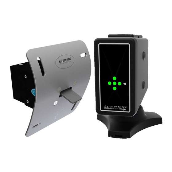
Dwg. 56201-2 SYSTEM DESCRIPTION The Safe Flight SCc Angle of Attack (AoA) System is an accurate wing lift measuring and display system designed as an aid to help the pilot achieve consistent takeoff, climb, cruise and landing approach performance. Using a wing leading edge flow measurement device, the SCc AoA System precisely senses the flow field about the wing’s leading edge. - Page 7 Page 6 of 28 Sym A Dwg. 56201-2 Table 2: Installation Parts Description Hardware Part Number Quantity Lift Transducer Doubler Doubler 3704-223-1 Plate Label Advisory Placard 55562-1 Backup Disc Assembly 1504-114-4 Ball Assembly 1504-128-4 Base & Spring Assembly 1504-126-4 Cover 1504-229-4 Cable Assembly, CAT5e 8 ft.
-
Page 8: Theory Of Operation
Page 7 of 28 Sym Dwg. 56201-2 Theory of Operation As the aircraft wing moves through the air it divides the air mass. At the center of this divided airflow is a narrow region known as the stagnation point. The location of the stagnation point uniquely represents the wing’s AoA. -
Page 9: Scope
Limitations 1.5.1 The Safe Flight SCc System is non-required and is to be used only as advisory information to the pilot. The system cannot replace the certified stall warning system. No performance credit can be taken from the system, such as reduced approach speeds, reduced takeoff or landing distances, etc. -
Page 10: Installation, Adjustment And Functional Check
Page 9 of 28 Sym Dwg. 56201-2 INSTALLATION, ADJUSTMENT AND FUNCTIONAL CHECK Installation Procedure The installation of the SCc AoA System requires installing the Lift Transducer on the leading edge of the wing, installing the Indexer Computer, and system wiring. After installation, both a ground functional and a flight check are performed. -
Page 11: Indexer Computer
Page 10 of 28 Sym Dwg. 56201-2 Make a mark on the wing corresponding to the center point of the vertically slotted holes in the Lift Transducer mounting plate. At these marks, drill two pilot holes through the wing and through the Doubler. When the Lift Transducer is installed, it should be able to be moved 0.25’’... - Page 12 Page 11 of 28 Sym Dwg. 56201-2 Next, the Base Assembly is mounted to the Backup Disc Assembly. Using MS24693-C28 screws or equivalent, attach the Base Assembly to Backup Disc through glareshield as shown above. Base Assembly Installation to Backup Disc Ball Assembly Installation to Indexer Computer Install the Ball Assembly through the Cover into the Indexer Computer.
- Page 13 Page 12 of 28 Sym Dwg. 56201-2 Ball Assembly Installation to Base Assembly Insert the Ball Assembly into the Base Assembly. Rotate the Indexer Computer until view of front face is acceptable. Lock the cover onto the Base Assembly. Locking the cover exercises the locking rings on the Base Assembly, requiring greater force to move the Indexer Computer.
-
Page 14: System Wiring
Page 13 of 28 Sym Dwg. 56201-2 System Wiring When ringing out wires in TYCO 1-794617-2 or equivalent connector, WARNING DO NOT insert oversized pins or probe into the main connector. Wire the system in accordance with the Wiring Schematic 70308800-15 Rev. A. Maximum current in any wire is 0.5 A. -
Page 15: Flight Check And Adjustment
NOTE verified prior to AoA System calibration. Background The Safe Flight SCc System is calibrated using a two-step process: accurate placement of the Lift Transducer, followed by an in-flight calibration procedure using Landing Approach and Low Airspeed Awareness data points. -
Page 16: In-Flight Final Calibration Adjustment
Page 15 of 28 Sym Dwg. 56201-2 In-Flight Final Calibration Adjustment Once the lift transducer has passed the transducer location verification flight, the system is ready for in-flight calibration. At a safe altitude for possible stall recovery, using the POH recommended landing approach speed, power setting, and flap extension, fly a simulated approach. -
Page 17: Final Lift Transducer Installation
Page 16 of 28 Sym B Dwg. 56201-2 In-Flight Final Calibration Adjustment (continued) If the calibration is unsuccessful, the system will return to flashing slowly for 5 seconds; then will transition again to flashing quickly for another 5 seconds. This sequence will repeat until the calibration is successful. Press and hold both the top and bottom button for two seconds to exit the calibration mode. -
Page 18: Failure Modes
Page 17 of 28 Sym B Dwg. 56201-2 Failure Modes The Indexer Computer and Lift Transducer are not field repairable. If the operation of the system is in doubt, apply power to the system. If the system successfully completes the Power-On Self-Test, then the system is in operation and can be flight checked. -
Page 19: User Manual
USER MANUAL General The Safe Flight SCc AoA System, when properly installed and calibrated in accordance with the installation instructions, will serve as a reliable aid for flight associated with normal and short-field takeoff, climb, long range cruise, maximum endurance, and normal and short-field landing approach. -
Page 20: Additional Button Press Functions
Page 19 of 28 Sym B Dwg. 56201-2 Additional Button Press Functions 5.4.1 Reference Marker 5.4.1.1 Overview The Reference Marker, a scrolling white LED arrow on the right-hand side of the Indexer Computer, is used to designate a pilot-selected AoA reference. The flight modes described below show the typical location to place the Reference Marker for the desired flight condition. -
Page 21: Takeoff And Climb
Page 20 of 28 Sym Dwg. 56201-2 Takeoff and Climb Normal Takeoff and Climb Set the Reference Marker at the center marker, adjacent to the three-dot center green indication. Fly the aircraft at the AFM/POH listed airspeed for the Normal Takeoff. After rotation, climb out using airspeed as the primary indication. - Page 22 Page 21 of 28 Sym Dwg. 56201-2 following example any particular aircraft NOTE make/model and is only given as a demonstration. The actual AoA cruise speed adjustment for headwind/tailwind will vary by specific aircraft. Consult the aircraft POH for the required speed (AoA) bias to be applied to the SCc for your aircraft Long Range Cruise Indications, Compensated for Wind (Typical)
-
Page 23: Landing Approach
Page 22 of 28 Sym Dwg. 56201-2 Landing Approach Normal Landing Approach Fly the aircraft at the speeds indicated by the FAA-approved POH/AFM, for the applicable gross weight and flap setting. When flying this approach speed, the centermark LEDs will be illuminated, as shown below. -
Page 24: Low Airspeed Awareness (Laa)
Page 23 of 28 Sym Dwg. 56201-2 Low Airspeed Awareness (LAA) The SCc AoA System is designed with an LAA function. When the airplane reaches the near maximum limit AoA, the Indexer Computer will display two flashing red LEDs and an increasing frequency of ‘Geiger counter’... - Page 25 Page 24 of 28 Sym Dwg. 56201-2 APPENDICES Appendix A: Method to Determine Lift Transducer Placement Appendix B: Flight Check Data Appendix C: Lift Transducer Adjustment Based on Indication...
- Page 26 Dwg. 56201-2 APPENDIX A APPENDIX A Method to Determine Lift Transducer Placement For the SCc AoA System to work properly, the Lift Transducer must be installed in the correct location. The correct spanwise location should be at least two feet outboard of any propeller slipstream, clear of any leading edge devices (stall strips, etc.) or internal obstructions (ribs) and, ideally, spanwise near the flap-aileron junction.
- Page 27 Dwg. 56201-2 APPENDIX B APPENDIX B Flight Check Data Aircraft Data Date Make Model Year Registration Number On Speed Calibration LAA Calibration Check Check Flaps DOWN, Flaps DOWN, Landing Approach Landing Approach Power Power kts IAS kts IAS Weight of airplane at time of above readings. Passengers Fuel Weight Empty Airplane Weight...
- Page 28 Dwg. 56201-2 APPENDIX C APPENDIX C LIFT TRANSDUCER ADJUSTMENT BASED ON INDICATION NOTE: This chart is included as a guide for the suggested movement of the Lift Transducer mounting plate based on the Indexer Computer indication during the initial flight check. Move Lift Transducer 1/4”...
Need help?
Do you have a question about the SCc Angle of Attack and is the answer not in the manual?
Questions and answers