Table of Contents
Advertisement
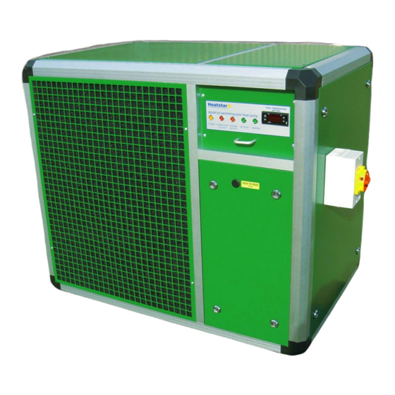
Aquarius
Product Manual
© Copyright HS Europe Limited 2009
All rights reserved. No part of this document may be stored in a retrieval system, or transmitted in any form or by any means to persons not
employed by Heatstar without written permission of HS Europe Limited.
Although every effort has been taken to ensure the accuracy of this document it may be necessary, without notice, to make amendments or
correct omissions. HS Europe Limited cannot accept responsibility for damage, injury, or expenses resulting there from.
Printed in the UK
Advertisement
Table of Contents

Subscribe to Our Youtube Channel
Summary of Contents for HeatStar Aquarius 1
- Page 1 All rights reserved. No part of this document may be stored in a retrieval system, or transmitted in any form or by any means to persons not employed by Heatstar without written permission of HS Europe Limited. Although every effort has been taken to ensure the accuracy of this document it may be necessary, without notice, to make amendments or correct omissions.
- Page 2 IMPORTANT This product has been thoroughly tested before leaving the Heatstar factory. However, please check at the earliest opportunity that the product has arrived in good condition and that no transport damage is apparent. If any damage is suspected, please contact the suppliers / carriers immediately.
- Page 3 The Heatstar product is in any way incorrectly applied for the application in terms of performance capacity or suitability. The Heatstar product is installed in any way that is not in accordance with current procedures as defined by HS EUROPE LIMITED from time to time and documented in the installation manual.
-
Page 4: Table Of Contents
HOW TO USE THIS MANUAL This manual provides information to support the installation and operation of the Heatstar product. The manual is divided into sections covering the various aspects of the installation and operation procedure. The following index is given to assist in locating and using the information contained within the manual :... -
Page 5: Warranty Registration
Do you wish to receive details relating to routine maintenance of the equipment at this time (See ‘maintenance’) : SEND TO : HS EUROPE LIMITED Manners View, Dodnor Park, Newport, Isle Of Wight, England, UK. PO30 5FA Heatstar would be pleased to provide a stamped, addressed envelope on request. Thank you for your assistance. -
Page 6: Product Overview
Fresh air is drawn through the Heatstar unit by the electric fan and chilled by the refrigeration system. The heat chilled from the fresh air, together with all the electrical energy consumed in operating the refrigeration circuit, is then transferred via a heat exchanger directly into the pool water as it is passed through the Heatstar unit. -
Page 7: Installation Requirement Summary
It does not matter if the unit is sited in sunlight or in shade. All that is required is a free flow of fresh air and that the air already used by the Heatstar unit is discouraged from re-cycling back into the unit. -
Page 8: Minimum Maintenance Access
MINIMUM MAINTENANCE ACCESS A minimum clearance of 900mm is required on the control panel side and on one other side of the Heatstar unit and 120mm minimum clearance on the other two sides. This represents the absolute minimum clearance required for essential maintenance. Ideally, considerably greater access all around the Heatstar unit is desirable. -
Page 9: Pool Water Plumbing
Heatstar unit. PIPE WORK CONNECTIONS : The inlet and outlet to the Heatstar unit are connected via the return line going to the pool i.e. after the pump and filter. The pool water inlet and outlet connections on the Heatstar unit are marked and must be connected as indicated. - Page 10 Effective operation of the Heatstar unit can only take place if the pool water filtration pump is providing an adequate flow of water to the unit. If the filter pump is not running then the Heatstar unit can not operate.
-
Page 11: Electrical Installation
ELECTRICAL INSTALLATION WARNING ! The Heatstar unit embodies electrical and rotational equipment. Only qualified personnel who thoroughly understand the operation of this equipment and any associated machinery should install, start-up or attempt maintenance of this equipment. Non-compliance with this warning may result in personal injury and / or equipment damage. - Page 12 Heatstar unit will be damaged. Such damage is not covered under the manufacturers warranty. CIRCUIT BREAKER : In addition to an RCD, the mains supply to the Heatstar unit must be protected by a Miniature Circuit Breaker (MCB). An MCB is a circuit protection device similar to a simple fuse, but re-settable.
- Page 13 Therefore time clocks etc. should not be installed on the heat pump. If the operation of the Heatstar unit is required to be limited on a time basis, then a time clock should be fitted to the pool filtration pump and the Heatstar unit will then function in line with the pool pump.
-
Page 14: Condensate Water Drainage
The left hand terminal of the pair carried a 240v supply on the control circuit and is protected by a 3 Amp fuse. If this supply is ‘returned’ to the right hand terminal of the pair (i.e. closed circuit), then the Heatstar unit will run normally. -
Page 15: Principle Of Control
The digital electronic thermostat control on the Heatstar unit is intended to automatically maintain the required pool water temperature. The thermostat measures the actual condition of the pool water as it is pumped through the Heatstar unit by the pool filtration pump and automatically switches ‘ON or ‘OFF’ heating accordingly. -
Page 16: About The Controls
Should this light, please refer to Fault finding. No pool water heating is possible until the cut-out has been re-set. ‘DE-FROST’ NEON - This neon, when lit, indicates that the Heatstar unit has sensed an excessive build up of ice on the cold refrigerated air coil and is acting to regulate ice formation. -
Page 17: Putting The Heatstar Unit Into Commission
The Heatstar unit cannot be started until the pool is full of water and the pool filtration circuit ready to operate. Before connecting the mains electricity supply to the Heatstar unit, the following procedure should be followed : CHECK ELECTRICAL SAFETY Check correct and good Earth connection. -
Page 18: Checking The Installation Services
Check that there is appreciable air flow from the air discharge vent on the Heatstar unit. CONDENSATE WATER DRAINAGE : If the Heatstar unit is located within a plant room, the small plastic drain out let on the base of the product must be connected to a suitable waste drain. -
Page 19: About The Warming Up Period
It should be noted that, if the pool water heating is switched ‘OFF’, the pool water will take a similarly long time to cool down. During the initial warming of the pool water, the Heatstar unit together with the pool filtration pump will require to operate continuously 24 hrs per day. -
Page 20: Icing Regulation
Therefore, ice is expected to form on the refrigerated air coil under certain conditions and this is perfectly normal. Even when ice has formed on the refrigerated coil, the Heatstar unit is still able to function normally and continue to heat the pool water. -
Page 21: Winterising
Disconnect and drain the pool water circulation pipe work circuit. Consider where such a large quantity of water will go! Flush out, using a hose, the pool water inlet and outlet connections on the Heatstar unit with FRESH water and drain again. -
Page 22: Corrosion Damage Prevention
All metals can be damaged through corrosion if exposed to pool water with an aggressive and incorrect chemical composition. In the case of the Heatstar unit, if the heating coil is damaged, then pool water may enter and contaminate the refrigeration system and repair costs can be very expensive indeed. - Page 23 INCORRECT WINTERISING : If the Heatstar unit and filtration system are not required to be in operation for a period of time and are not flushed with fresh water, then the conditions of the stagnant pool water retained within the system may prove damaging.
-
Page 24: Fault Finding
WATER FLOW CUT-OUT : If this red neon is lit then there is insufficient flow of pool water through the Heatstar unit. If this is lit, check that : The pool water filtration pump is running. Any valves controlling flow through the Heatstar unit are in the correct position. - Page 25 Heat pump ‘Over heating’ is caused by a problem with inadequate pool water flow or air in the pool filtration circuit. It is simply a reflection that all the heat generated by the Heatstar unit is not being carried away by the flow of pool water.
- Page 26 If the control setting temperature is set very high and the green neon remains off, then this may indicate a faulty thermostat. Contact Heatstar for advice. The Heatstar unit and the pool filtration pumps are not on time clocks. The pool or the pool filtration pipe work are not leaking – switch off any automatic pool top-up.
-
Page 27: Extended Warrantees
HEATSTAR EXTENDED WARRANTEES In the UK the Heatstar is supported by a full parts and labour warranty which initially runs for one year from the original supply date. When this initial period expires, continuing extended warranty cover is then available at an additional premium. -
Page 28: Ec Declaration Of Conformity
DISPOSAL OF REDUNDANT PRODUCT The refrigeration circuit within the Heatstar incorporates refrigerant and oil. When the time comes to renew the Heatstar, a refrigeration company should be employed to recover any remaining refrigerant and to safely dispose of the oil.
Need help?
Do you have a question about the Aquarius 1 and is the answer not in the manual?
Questions and answers