Table of Contents
Advertisement
Quick Links
Advertisement
Table of Contents

Related Manuals for M. Bartels Stairclimber TRE-70

Summary of Contents for M. Bartels Stairclimber TRE-70
- Page 1 Operation Manual Stairclimber TRE-70 FE-32-2...
- Page 2 INTRODUCTION Thank you for purchasing STAIR X TRE-70, SUNWA POWERED STAIR CLIMBER. This manual describes proper operation procedure, inspection and maintenance. Before running the machine, be sure to read this manual thoroughly. Please keep this manual in the same, easily accessible place. All machines are referred to by their serial numbers.
-
Page 3: Table Of Contents
CONTENTS ESSENTIALS OF SAFE OPERATION....................5-7 CONFIGURATION AND SPECIFICATIONS....................8 PRODUCT CONFIGURATION...........................8 SPECIFICATIONS ............................8 PARTS................................ 9 DESCRIPTION OF PARTS........................10-12 KEY SWITCH............................10 STAIRS/GROUND TRANSFER / LOADING / UNLOADING SELECTION SWITCH..........10 RAIL SWITCH............................10 OPERATION SWITCHES..........................11 BATTERY PACK REMOVAL/INSTALLATION....................11 BATTERY GAUGE INDICATION........................12 BATTERY CHARGE SYSTEM......................13-17 BATTERY...............................13 CHARGER..........................13 CHARGING... - Page 4 SAFETY PRECAUTIONS To maintain safe operation, important safety precautions, classi ed into Danger, Warning and Caution, are indicated in corresponding parts of the operation manual. The de nition of each precaution is explained in the following section. Neglecting this warning indication or operating the machine improperly may cause serious personal injury or even death.
- Page 5 AFTER-PURCHASE SERVICING LOCATIONS OF SAFETY WARNING LABELS For fear of falling, the front casters of wheelchair WARNING must not be placed beyond this line ● Warranty and repair Do not load on the Ramp except for loading wheelchair. 1) The term of the warranty is one year from the purchase date. The distributor from which you made a purchase will repair your product.
-
Page 6: Essentials Of Safe Operation
1. ESSENTIALS OF SAFE OPERATION Bevor using STAIR X This machine cannot be used on spiral stairs, curved stairs, stairs with a slope angle of over 35 de- grees, or stairs with rough edges. 30 to 35 degrees 30 to 35 degrees 20 to 30 degrees 20 to 30 degrees <Spiral staircase>... - Page 7 2. Handling of Battery • Battery is a sealed type. It is unnecessary to refi ll it with water. Never dismantle Battery. • Never position Battery near a fl ame or short-circuit Battery. • If Battery is cracked and its electrolytic solution contacts skin or clothes, immediately rinse the contaminated area with plenty of clean water.
-
Page 8: Configuration And Specifications
2. CONFIGURATION AND SPECIFICATIONS 2.1 PRODUCT CONFIGURATION The “STAIR X TRE-70” Battery-powered Stair Climber model contains the following parts. Floor Winch (optional) • • Handle Battery Pack 2 units • • Drive Unit S t a n d a r d Cargo Tie 1 piece (5 m) •... -
Page 9: Parts
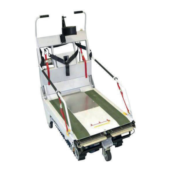
3. PARTS Belt hook fixed position (six positions in total) Travelling Wheels Front wheel (swivel) Hydraulic Cylinder Rubber Crawlers Travelling Wheels Rear wheel (fixed) Rail Reduction Gear Operation Panel (switches) Sensor Manual Switches (For how to use the Manual Switches, refer to 12. How to use the Manual Switches on page 34.) Floor Knob bolt... -
Page 10: Description Of Parts
4. DESCRIPTION OF PARTS 4.1 KEY SWITCH Indicator Lamp The Key Switch on the operation panel turns the power on and off. Turning the Key Switch clockwise turns the power on, and turning it counterclockwise turns the power off. The LED goes on (Ready) after three seconds after the Key Switch is turned on, making the machine ready for operation. -
Page 11: Operation Switches
4.4 OPERATION SWITCHES 2) UP/DOWN Selection Switch 3) Emergency Stop Switch 1) Run Switches (push-button) Stairs: The machine is activated only when the Run Switches on both sides are being pressed. Lifting your fi nger off even one side of the switch causes the machine to stop. Ground Transfer: The Floor is lowered and the Travelling Wheels touch the fl... -
Page 12: Battery Gauge Indication
4.6 BATTERY GAUGE INDICATION The position of the LED illumination on the Battery Gauge shows the remaining battery capacity. CAUTION • Do not turn the Key Switch on when the battery is being charged. • Doing so causes the Battery Gauge to indicate the Battery Pack is fully charged even when the charging process has not yet been completed. -
Page 13: Battery Charge System
5. BATTERY CHARGE SYSTEM 5.1 BATTERY A Sealed Lead Battery is used in STAIR X. It is a maintenance-free and non water requiring Battery. Whenever Battery is handled, be sure to follow the cautions shown below. NOTE: Immediately after Battery is used, Battery must be charged using Battery Charger of STAIR X. If insuffi... -
Page 14: Charging Procedure
5.3 CHARGING PROCEDURE 1.1) If the Battery Pack has not yet been detached for charging, connect the Charger’s Plug to the Receptacle on the side of the Switch Box. 1.2) If the Battery Pack has been detached for charging, connect the Charger’s Plug. Receptacle 2.) If the Battery Packs are removed from the STAIR X: Charging... -
Page 15: Voltage Range Selection
Turn on Charger´s Power Switch (Set it to —). When Red and Yellow LEDs illuminate, the charging process will start. When the charging process advances and Green LED illuminates instead of Yellow LED, the charging process will stop. Turn off Charger´s Power Switch (Set it to O). Disconnect Power Plug from the 115 V/230 V AC outlet. -
Page 16: Malfunction, Inspection, Resolution Rocedure
5.6 MALFUNCTION, INSPECTION, RESOLUTION PROCEDURE TROUBLE CAUSE COUNTERMEASURE Insuffi cient insertion of Power Plug Check outlet and securely connect into outlet. Power Plug. Check power and other relevant No power is supplied. parts. Power Cord is broken. Arrange its repair or replacement. No power supplied. -
Page 17: Battery Replacement
5.7 BATTERY REPLACEMENT 1. Unscrew the screw mounting Battery Case and Cover. Battery Screw Battery Case 2. Disconnect cables from Battery Terminals, Floating Connector remove exhausted Batteries, and install new ones. Black 3. Connect cables to Battery Terminals as shown Battery in the fi... -
Page 18: Pre-Use Inspection
6. PRE-USE INSPECTION Before using the machine, be sure to carry out the daily inspection. The daily inspection will prevent trouble. It is essential before handling STAIR X. If any problem is found in each inspection, take appropriate measures, referring to 9. Inspection and Maintenance on page 32. - Page 19 SEATBELT INSPECTION WHEELCHAIR SECURING STRAP INSPECTION Wheelchair Two locations, one each Two locations, one each Front Rear for the right and left for the right and left Seatbelt Wheelchair Wheelchair Fixing Belt Fixing Belt Check that the seatbelt and buckles Check that the wheelchair securing straps exhibit exhibit no cracking or damage and that no deformation or cracking and that they function...
- Page 20 RUBBER CRAWLERS CHECK FOR UNUSUAL NOISES INSPECTION Motor, Reduction Gear Slip sign Check the Rubber Crawlers for any cracking Check for unusual noises, cracks, or or wear (whether the slip sign is visible or not), hydraulic leakage. or for any misalignment that might exist in the crests of both Rubber Crawlers.
-
Page 21: Operating Procedure
7. OPERATING PROCEDURE 7.1 LOADING THE WHEELCHAIR Stairs/Ground Transfer/Loading/ Unloading Selection Switch 1) Leave clearance of about two meters in the front and to the rear of the STAIR X. • Be sure to load/unload the wheelchair on fl at ground. Key Switch Approx. - Page 22 8) Apply the brake on the wheelchair. When using an electric wheelchair, make sure that the power is turned OFF. Main switch turned [OFF] Parking brake [ON] 9) To avoid the danger that the wheelchair may move Two locations, one each Two locations, one each Front Rear...
-
Page 23: Unloading The Wheelchair
If the seatbelt is not locked in properly, STAIR X will not operate. CAUTION Be sure to fasten the seatbelt for the safety of the passenger and the operator. 13) Retract the slope into the original position. Slope Lock Tie •... -
Page 24: Loading The Wheelchair Using The Winch (Optional)
7.3 LOADING THE WHEELCHAIR USING THE WINCH (OPTIONAL) • For how to extend/retract the slope, refer to steps 1) to 5) in Section 7-1. 1) Turn the Key Switch on the operation panel to the ON position. 2) Select the “TRANSFER” mode using the “MODE” Switch. -
Page 25: Unloading The Wheelchair Using The Winch (Optional)
8) Once the wheelchair has been loaded on the fl oor, release the UP button on the remote controller, and then have the operator push the wheelchair forward until the front wheels stand back behind the arrow (red) and until the rear wheels touch the back part of the fl... -
Page 26: Ascending Stairs
7.6 ASCENDING STAIRS • Before each step, be sure to ensure the safety of others in the area. (1) Positioning the machine to ascend Use the Travelling Wheels to approach the foot of the stairs, and then set the machine (facing back- ward) perpendicular to the stairs. - Page 27 2) Hold the handgrips on both sides of the handle securely, and then press both of the RUN Switches with your fi ngers at the same time. The machine starts ascending the stairs. Lifting your fi ngers off the switches causes the STAIR X to stop in place.
- Page 28 4) Even after the Rubber Crawlers have touched the landing or fl at ground, keep pressing the Travelling Switches and pull the machine backward for over approx. 30 cm from the top of the stairs. RUN Switches 5) If the operator selects the “GROUND” mode using the “MODE”...
-
Page 29: Descending Stairs
7.7 DESCENDING STAIRS Stairs/Ground Transfer/Loading/Unloading Selection Switch • Before each step, be sure to ensure the safety of others in the area. (1) Positioning the machine to descend Approach the top of the stairs using the Travelling Wheels and stop the machine approx. - Page 30 (3) Ending descent 1) When the machine has fi nished its descent, continue pressing and holding the RUN Switches until it stops after moving approx. 1 meter forward. RUN Switches Approx. 1m Stairs/Ground Transfer/Loading/Unloading Selection Switch 2) If the operator selects the “GROUND” mode using the “MODE”...
-
Page 31: Daily Maintenance And Storage
8. DAILY MAINTENANCE AND STORAGE 8.1 CONSIDERATIONS FOR KEEPING STAIR X Avoid keeping this product in: • Locations where the ambient temperature or relative humidity exceeds the specifi ed range; • Locations where condensation may form because of sudden fl uctuations in temperature; •... -
Page 32: Inspection And Maintenance
9. INSPECTION AND MAINTENANCE Performing daily inspections and maintenance greatly affects the life of the machine. We strongly advise that you perform periodic self inspection and maintenance in order to prevent trouble from occurring and ensure the safe and extended use of the machine. Inspection Point Inspection Details Action... -
Page 33: Troubleshooting
10. TROUBLESHOOTING Problem Cause Remedy There is no • The Key Switch is not turned on. • Turn the Key Switch to the right to set it to the indication on the ON position. Battery Gauge. • The Battery has not been charged. •... -
Page 34: Indicator Lamp Indications And Countermeasures
11. INDICATOR LAMP INDICATIONS AND COUNTERMEASURES If any problem occurs, such as a failure, the indicator lamp on the operation panel fl ashes, and at the same time, the operator hears the audio warning saying “STAIR X has stopped running.” The number of times the lamp fl ashes indicates the possible causes of the problem. -
Page 35: How To Use The Manual Switches
12. HOW TO USE THE MANUAL SWITCHES The basic instructions for using the Manual Switches are shown in the right illustration. Manual operation is also possi- ble in the following cases. • When loading this machine into vehicles with limited height, such as minivans, you have two choices: You can load the machine with the handle folded down or you can load the machine by controlling it manually... -
Page 36: Chimes And Volume Control
13. CHIMES AND VOLUME CONTROL “Ding-dong” Chime • If both sides of the Travelling Switches are pressed when either “Stairs” or “Ground Transfer” mode is selected, the Chime sounds “Ding-dong” to warn people nearby. The Chime does not sound when only one side of the switches is pressed. -
Page 37: After-Purchase Servicing
4) Push the High Speed button for both of the fl oor and the travelling wheels on the manual switch panel and push the Rail Bent button on the operation panel, at the same time. 5) Set the Operation Switch on the manual switch panel back to the “AUTO”... - Page 38 16. DEALER Austria/Czech Germany Latvia Lehner Lifttechnik GmbH S alling 8 Perfekta-Lift GmbH E levet SIA 4724 Neukirchen am Walde Glehner Heide 1 Vestienas street 20 P hone: +43 7278 3514 41352 Korschenbroich LV 1035 Riga F ax: +43 7278 3514-12 P hone: +49 2182 886060 Phone: +371 25708022 office@lehnerlifttechnik.at F ax: +49 2182 8860610 Fax: +371 67574023 www.lehner-lifttechnik.at ...
- Page 39 Slovenia JR Product d.o.o. S tegne 7 1000 Ljubljana Phone: +386 1511 4482 F ax: +386 1511 4483 info@jr-product.si www.jr-product.si Spain Stannah Incisa S.L.U. c/ Eduard Marquina 26 08911 Badalona Phone: +34 93 4646770 F ax: +34 93 3891534 otecnica@stannah.es www.stannah.es Spain Enier Av. De Franca 205 17840 Sarrià de Ter Phone: +34 972 171374 Fax: +34 972 170678 enier@enier.com w ww.enier.com Switzerland ...
- Page 40 M. BARTELS Reha Im - & Export GmbH Fangdieckstr. 68 22547 Hamburg Tel. +49 (0) 40 | 54 75 33 33 m.bartels@reha-europe.com www.reha-europe.com Presented by:...
Need help?
Do you have a question about the Stairclimber TRE-70 and is the answer not in the manual?
Questions and answers