
Related Manuals for Bitmos sat801+


Summary of Contents for Bitmos sat801+
- Page 1 © Bitmos GmbH Himmelgeister Straße 37 D-40225 Düsseldorf Germany Tel.: +49 (0) 211 / 60 10 10 - 30 Fax: +49 (0) 211 / 60 10 10 - 50 E-Mail: info@bitmos.de Internet: www.bitmos.de 36-8101.EN – TD075215 09.12.2013...
-
Page 2: Table Of Contents
sat801+ Pulse Oximeter 1 General ............................. 5 1.1 Information on operating instructions ...................5 1.2 Symbol designation......................5 1.3 Liability and warranty ......................6 1.4 Copyright protection......................7 1.5 Removal and disposal......................7 2 Safety............................8 2.1 Intended use........................8 2.1.1 Possible misapplications....................8 2.2 User responsibility .......................9 2.3 Possible dangers from the equipment................10 2.4 Users ..........................11 2.5 Customer service.......................11... - Page 3 sat801+ Pulse Oximeter 7.2.2 Calling the main menu....................33 7.2.3 Menu structure ......................33 7.3 Switching On ........................33 7.4 Turning the unit off......................35 7.5 Alarm limits (Alarm limits) ................... 37 7.5.1 Setting the alarm limits ....................37 7.5.2 Setting the Alarm Filter ....................39 7.6 Configuration (Configuration) ..................
- Page 4 sat801+ Pulse Oximeter 11 Cleaning and Maintenance ....................67 11.1 Cleaning ..........................67 11.1.1 Cleaning the Unit .......................67 11.1.2 Cleaning of the Masimo-Sensors ................67 11.1.3 Cleaning of Patient Cables ..................68 11.2 Maintenance ........................68 11.2.1 Yearly Maintenance ....................68 11.2.2 User Check of Alarm Function ...................68 12 Accessories and replacement parts ...................
-
Page 5: General
sat801+ Pulse Oximeter General 1 General 1.1 Information on operating instructions These operating instructions describe the safe and appropriate handling of the unit. Adherence to specific safety notices and instructions as well as to the applicable on-site accident prevention regulations and general safety regulations is an imperative requirement. Before beginning all work on the unit, read the operating instructions completely;... -
Page 6: Liability And Warranty
sat801+ Pulse Oximeter General 1.3 Liability and warranty All data and notices in this operating manual were arranged in consideration of valid regulations, the current state of the art, as well as our many years of knowledge and experience. This operating manual must be read carefully before beginning all work on and with the unit! The manufacturer does not accept liability for damages and malfunctions that result from not observing the operating instructions. -
Page 7: Copyright Protection
sat801+ Pulse Oximeter General 1.4 Copyright protection The instruction manual is to be kept confidential. It is exclusively intended for active personnel that work on and with the unit. All textual data, texts, drawings, illustrations, and other representations are predicted by copyright laws and are entitled additionally to commercial patent rights. -
Page 8: Safety
The unit may not be opened or altered except for changing the battery. Parts other than those pertaining to the supply scope may be used only after release by the company, Bitmos GmbH. 2.1.1 Possible misapplications WARNING! Fire Hazard! The pulse oximeter may not be used during nuclear magnetic resonance imaging tests. -
Page 9: User Responsibility
sat801+ Pulse Oximeter Safety – Pulse rate measurement is based on the optical detection of a peripheral flow pulse and therefore may not detect certain arrhythmias. The pulse oximeter should not be used as a replacement or substitute for ECG based arrhythmia analysis. –... -
Page 10: Possible Dangers From The Equipment
sat801+ Pulse Oximeter Safety The unit may only be used in technically sound and operational condition. Before each use the unit must be examined for any possible defects. The directions in the user manual are to be followed completely and without any changes! In order to use the unit, the directions in this user manual, the stated safety indicators, the local accident prevention regulations and general safety guidelines, as well as current environmental provisions are to be observed and implemented. -
Page 11: Users
The unit may only be used by trained specialists and instructed users. The configuration of the unit (e.g. the alarm limits) in particular has to take place with corresponding medical expertise. 2.5 Customer service You can contact Bitmos GmbH as follows: Office hours: Mo-Fri 8.00 a.m. - 4.00 p.m. -
Page 12: Technical Data
sat801+ Pulse Oximeter Technical data 3 Technical data 3.1 Unit data Feature Value Unit dimensions (L x W x H) 128 x 85 x 46 mm Weight, including batteries 230 g External power supply 240 V ~50 Hz 5 V DC 1 A Internal power supply LiIonMn 2 x 3.6 V / 2250 mAh (each) Maximum service life with battery... - Page 13 sat801+ Pulse Oximeter Technical data NOTICE! A functional tester cannot be used to assess the accuracy of a pulse oximeter probe or a pulse oximeter. NOTICE! If there is independent demonstration that a particular calibration curve is accurate for the combination of a pulse oximeter and a pulse oximeter probe, then a functional tester can measure the contribution of a monitor to the total error of a monitor/probe system.
-
Page 14: Factory Default Settings
sat801+ Pulse Oximeter Technical data 3.2 Factory default settings Setting Value Alarm limit SpO high 100 % Alarm limit SpO 85 % Alarm limit Pulse high 160 1/min Alarm limit Pulse low 40 1/min Alarm filter SpO Alarm filter Pulse high Memory configuration Permanent, overwrite SmartTone... -
Page 15: Assembly
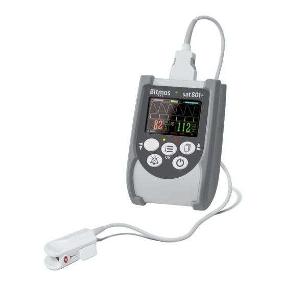
sat801+ Pulse Oximeter Assembly 4 Assembly 4.1 Displays and controls TFT display green LED red alarm LED micro SD card slot Navigation button right / up On / Off button Loud speaker Alarm mute button Menu / OK button Navigation button left / down yellow alarm LED Fig. -
Page 16: Lcd Display
sat801+ Pulse Oximeter Assembly 4.3 LCD display Perfusion index,, graphical and numerical representation Plethysmogram, displays the actual and normalized pulse curve in standard display mode Signal IQ – bouncing bar display, displays graphically the current Signal-IQ-value; the Signal-IQ-value represents the signal inadequacy display Oxygen saturation in % Data storage capacity in %... - Page 17 sat801+ Pulse Oximeter Assembly What is signal IQ™? Signal-IQ™ is a measurement for Signal-Identification and Signal-Quality. Masimo developed this indicator to give the user information when a measurement is questionable. Signal-IQ™ is a visual reliability indicator for the oxygen saturation and pulse frequency measurements.
-
Page 18: Pictograms On The Unit
sat801+ Pulse Oximeter Assembly 4.4 Pictograms on the Unit Symbol Bedeutung Consult instructions for use! On / Off button Menu / OK button Navigation button right / up Navigation button left / down Alarm tone mute IP 22 Ingress Protection Rating Manufacturer Ambient pressure range storage condition Humidity storage range condition... - Page 19 (1). NOTICE! It is not possible to connect the patient connector and the USB cable at the same time. NOTICE! Fig. 3: USB-Interface The necessary Interface software is available from the medical devise supplier or directly from Bitmos GmbH.
-
Page 20: Shipping, Packaging And Storage
sat801+ Pulse Oximeter Shipping, Packaging and Storage 5 Shipping, Packaging and Storage 5.1 Shipping inspection Examine the delivery immediately upon receipt for completeness and possible shipping damage. With visible external shipping damage do not accept delivery or only with reservation. Indicate the extent of damage on the accompanying delivery document i.e. -
Page 21: Use
sat801+ Pulse Oximeter 6 Use 6.1 Environmental Conditions The unit uses high frequency energy exclusively for its internal functions. That is why its high frequency emission is very low and it is improbable that electronic units in close vicinity can be disturbed. -
Page 22: Battery Operation
sat801+ Pulse Oximeter Connect the network adapter plug (1) to the unit connector (2) Plug the other end of the cable into an electric outlet. Fig. 4: Plug adapter cable into socket The Network-LED (1) displays. NOTICE! The Network-LED only signals that the unit is supplied with electricity. - Page 23 sat801+ Pulse Oximeter For charging, connect the mains adapter plug to the unit connector. Plug the other end of the cable into an electric outlet. Fig. 6: DC power adapter The green power LED (1) displays. NOTICE! The green power LED only signals that the unit is supplied with electricity.
-
Page 24: Changing The Energy Supply
sat801+ Pulse Oximeter 6.3.3 Changing the energy supply The unit can be supplied either by the mains network (with the power plug adapter) or by the internal rechargeable batteries. 6.3.3.1 Changing from mains to battery supply Unplug the power supply from the mains network. -
Page 25: Changing From Battery To Mains Supply
sat801+ Pulse Oximeter After 30 seconds the alarm will be reset and the display returns to standard mode display. Now, the unit is supplied by the internal batteries. Fig. 11: Standard display mode 6.3.3.2 Changing from battery to mains supply The device is in battery operation. - Page 26 sat801+ Pulse Oximeter Connect the patient cable connector (1) into the unit socket (2). The plug only fits in one direction and audibly snaps in. Select the required Masimo-Sensor. Fig. 14: Connect patient cable Insert the sensor connector into the patient cable connector.
-
Page 27: Disconnecting The Sensor From The Patient Cable
sat801+ Pulse Oximeter 6.4.2 Disconnecting the sensor from the patient cable LNOP sensors Press the two disconnect buttons (1) together. The locking mechanism unlocks the sensor plug. Remove the plug from the coupling (2). Fig. 17: LNOP sensor coupling LNCS sensors Lift the protective cover (1). -
Page 28: Installing The Unit
sat801+ Pulse Oximeter 6.5 Installing the unit Install the unit in such a way so that it interferes with the patient’s mobility as little as possible. Under normal circumstances, the unit should be positioned on the night table next to the patient’s bed. -
Page 29: Using Masimo Sensors
sat801+ Pulse Oximeter 6.6 Using Masimo sensors WARNING! Danger from not observing user instructions! Pay attention to the notices in the user instruction manual for Masimo sensors. If not observed the measurement results can be false. Only use approved Masimo sensors with the unit. Use of other sensors can reduce the performance capacity of the unit and thus produce danger to the patient! Tissue damage can be caused by incorrect application or use of a sensor, for example by wrapping the sensor too tightly. -
Page 30: Selecting The (Correct) Sensor
sat801+ Pulse Oximeter 6.6.1 Selecting the (correct) sensor Select the sensor based on the patient’s age and weight and its re-usability. This table is a guide. The correct sensor has to be matched individually to the patient. NOTICE! The latest list of all sensors is directly available from the manufacturer. Disposable sensors Product code Sensor Type... - Page 31 sat801+ Pulse Oximeter Reusable sensors Product code Sensor Type Patient Type and Weight ® 16-1269 LNOP Adults > 30 kg ® 16-1276 LNOP DCIP Children > 10 kg and < 50 kg ® 16-1396 LNOP DCSC Adults > 30 kg, Spot Check-Applications ®...
-
Page 32: Operation
sat801+ Pulse Oximeter Operation 7 Operation 7.1 General Control of the unit takes place on the display in combination with the control buttons. In the directional text of this user manual, the texts, appearing in the display, are highlighted to assist in understanding. -
Page 33: Calling The Main Menu
sat801+ Pulse Oximeter Operation 7.2.2 Calling the main menu Press the menu button The main menu is displayed. Fig. 21: Main menu 7.2.3 Menu structure The menu structure is as follows: Level 1 Level 2 Level 3 Remark Alarm limits Setting the alarm limits and alarm filter parameters Data... - Page 34 sat801+ Pulse Oximeter Operation Press On/Off button An optical, audio, and internal self test is completed: – The LEDs are activated. – An alarm sound is issued. – The unit goes through extensive internal hardware testing. Fig. 22: Power-up screen ATTENTION! TOO SILENT ALARMS! If the alarm tone volume setting is...
-
Page 35: Turning The Unit Off
sat801+ Pulse Oximeter Operation ATTENTION! Unsuccessful tests! If one or several tests are not successfully executed, an error message is displayed in the display. The unit can and may not be used on patients. Fig. 25: Power-up error message ATTENTION! Defective alarm loudspeaker! The sat801+ system is equipped with a redundant alarm loud... - Page 36 sat801+ Pulse Oximeter Operation minimal non-zero value = 01. For Perfusion Sensitivity, the manufacturer’s default setting will be set. To turn the unit OFF: Press the On-/Off button approx. 2 seconds. The display shows the turn-off confirmation message. Press the On-/Off button again.
-
Page 37: Alarm Limits (Alarm Limits)
sat801+ Pulse Oximeter Operation 7.5 Alarm limits (Alarm limits) CAUTION! Changing the alarm settings is a serious intervention in the device functions and must never be done without first consulting the doctor in charge of the treatment! NOTICE! Until the modified alarm limit value has been accepted, the most recently stored value remains in force. - Page 38 sat801+ Pulse Oximeter Operation Select SpO2 hi , for setting the upper SpO2 alarm limits, select SpO2 lo for setting the lower SpO2 alarm limit Select PR hi, for setting the upper pulse rate alarm limit, select PR lo for setting the lower pulse rate alarm limit.
-
Page 39: Setting The Alarm Filter
sat801+ Pulse Oximeter Operation 7.5.2 Setting the Alarm Filter CAUTION! Activating or changing the alarm filter settings is a serious intervention in the device functions and must never be done without first consulting the doctor in charge of the treatment! For canceling short and therefore irrelevant alarm conditions, an alarm filter can be set. - Page 40 sat801+ Pulse Oximeter Operation Select the alarm filter to be changed and confirm it. Set the new period (in seconds) value and confirm it. Fig. 35: Modifying the alarm filter Set other values if needed. Leave the menu with Return. Confirm all new values by confirming the safety question Accept? Y/N.
-
Page 41: Configuration (Configuration)
sat801+ Pulse Oximeter Operation 7.6 Configuration (Configuration) 7.6.1 Screen options (Screen) Starting from the main menu, call: Configuration Screen Select Backlight, Mode or Language Confirm the selection. Fig. 37: Screen selection Fig. 38: Screen submenus 7.6.1.1 Backlight (Backlight) This function activates the LCD backlight; settings are “ON” and “AUTO”. –... -
Page 42: Menu Language (Language)
sat801+ Pulse Oximeter Operation Starting from the main menu, call: Configuration Screen Backlight The setting options ON or AUTO can be selected with the navigation keys. NOTICE! The changes made will be shown in the settings. Confirm the selection. Fig. 39: Backlight 7.6.1.2 Menu language (Language) This function sets the menu language. - Page 43 sat801+ Pulse Oximeter Operation – The “HomeCare mode” access protects the inexperienced user from modifying important monitoring parameters. These parameters are invisible. – The “Clinic mode” access allows users to set all the configuration parameters. – The “Sleep Lab mode” will turn off all alarms during monitoring. This is useful for overnight sleep studies.
- Page 44 sat801+ Pulse Oximeter Operation Access permissions HomeCare on HomeCare off Alarm limits Alarm filter Vital alarm list Total alarm list Trend Pulse tone volume Alarm tone volume +/- (Off is not available) Alarm tone suppression time Erase data Overwrite data Masimo averaging time Masimo perfusion sensitivity SmartTone...
-
Page 45: Acoustical Alarms (Acoust. Alarms)
sat801+ Pulse Oximeter Operation NOTICE! An invalid access code is answered by the error message: "Incorrect access code! “ Re-enter the correct code. Fig. 43: Invalid access code 7.6.2 Acoustical alarms (Acoust. alarms) Starting from the main menu, call: Configuration Acoustic. -
Page 46: Alarm Tone Volume (Volume Alarm)
sat801+ Pulse Oximeter Operation Fig. 45: Pulse tone volume NOTICE! This de-activation of the pulse signal tone is not shown on the display. 7.6.2.2 Alarm tone volume (Volume Alarm) Starting from the main menu, call: Configuration Acoust. Alarm Volume Alarm Adjust the alarm tone volume from OFF und loud (10). -
Page 47: Masimo Signal Processing (Signalprocessing)
sat801+ Pulse Oximeter Operation Starting from the main menu, call: Configuration Acoust. Alarms Silence Time Set the alarm tone silence time between 30 and 120 sec. Confirm this setting with RETURN. NOTICE! During the alarm silence time, the display shows the alarm silence Fig. -
Page 48: Perfusion Sensitivity (Algorithm Mode)
sat801+ Pulse Oximeter Operation CAUTION! Variations in oxygen saturation cannot be recognized! Rapid changes in oxygen saturation are not recognized with the selection of a long averaging time! Starting from the main menu, call: Configuration Signal process Averaging time Set the averaging time between 2-4 and 16 sec. -
Page 49: Smarttone (Smarttone)
sat801+ Pulse Oximeter Operation APOD may be appropriate under conditions in which the Clinician/Patient ratio is lower than in the intensive care unit and when contact between clinician and patient may be less continuous. It is recommended for "step down" and "ward" care, and nursing home care situations. -
Page 50: Artifact Filter (Artifact-Filter)
sat801+ Pulse Oximeter Operation Starting from the main menu, call: Configuration Signal process. Smart Tone Select the setting (on/off). Confirm this setting with RETURN. Fig. 51: SmartTone 7.6.3.4 Artifact filter (Artifact-filter) The Artifact filter rejects sensor-related alarm messages that are shorter than 5 seconds. A sensor alarm must be at least for 5 seconds of the same type to be processed. -
Page 51: System Time (Clock)
sat801+ Pulse Oximeter Operation 7.6.4 System time (Clock) The function sets the date and time of the unit. For a precise analysis of the stored monitoring data, it is necessary to set the device time always correctly. ATTENTION! The user will need to adjust the time from summer to winter and vice versa manually! Starting from the main menu, call: Configuration Clock... -
Page 52: Alarms
sat801+ Pulse Oximeter Alarms 8 Alarms 8.1 In General As a monitoring system the unit has been equipped audio and optical signals for a multiple number of alarm situations. Alarms are activated: When deviations from pre-set value limits occur – In problem situations during technical monitoring –... -
Page 53: Alarm Categories
sat801+ Pulse Oximeter Alarms For canceling short and therefore irrelevant alarm conditions, an alarm filter can be set. The alarm filter produces a “silent alarm”. During the set alarm filter time period (adjustable between 0=OFF and 20 seconds maximum), the occurrence of an alarm condition for oxygen saturation and/or pulse rate will NOT lead to an acoustical nor optical alarm. -
Page 54: High Priority Alarms
sat801+ Pulse Oximeter Alarms 8.3.1 High Priority Alarms WARNING! Wrong alarm limits! Check the alarm limits each time the device is used to ensure they are appropriate for the patient being monitored. High priority alarms require immediate user intervention in order to avoid possible damage to the patient. -
Page 55: System Alarms
sat801+ Pulse Oximeter Alarms Possible Cause Description Solution Sensor not The patient cable is not or incorrectly Check connection connected connected to the unit. between unit and sensor. The connection between sensor input and If needed, replace sensor patient cable is interrupted. or patient cable. - Page 56 sat801+ Pulse Oximeter Alarms System alarm messages: Message Source The battery voltage is below a level that guarantees SYST ALARM: bat low! reliable operation. SYST ALARM: MS-FIFO! An error has arisen in the Masimo input data memory. The Masimo-circuit board has not responded to several SYST ALARM: MS-timeout! queries.
-
Page 57: Mid-Level Priority Alarm
sat801+ Pulse Oximeter Alarms 8.3.2 Mid-level Priority Alarm WARNING! Insufficient monitoring at mid-level priority alarms. With alarms of mid-level priority a correct signal processing cannot be guaranteed. At times the patient will not be monitored correctly for the duration of the alarm. The cause of the alarm must be corrected as soon as possible. - Page 58 sat801+ Pulse Oximeter Alarms Possible Cause Description Solution Unknown Sensor The unit has discovered a Only connect approved Masimo sensor not approved for this sensors! system. Battery depleted Remaining operation time of Recharge battery 15 minutes or less...
-
Page 59: Low-Level Priority Alarms
sat801+ Pulse Oximeter Alarms 8.3.3 Low-level Priority Alarms With a low-level priority alarm – the audio sound of low-level priority is heard, – the yellow alarm indicator lights continuously and – alarm message in the status line Low-level priority alarms: Status line message Description Solution... -
Page 60: Data
sat801+ Pulse Oximeter Data 9 Data 9.1 Alarm lists (Alarm lists) The sat801+ continuously stores monitoring data. SpO2, pulse and IQ values are continuously logged on a second-by-second basis. In addition, data related to monitoring, such as alarms and device settings, are also stored. In the basic extension stage, the device stores 160 hours of continuous monitoring with a maximum of 4000 alarm list entries. -
Page 61: Total Alarm List (Vital Alarm List)
sat801+ Pulse Oximeter Data 9.1.2 Total alarm list (Vital alarm list) Selecting Total alarm list displays a list of all the alarm events (vital and technical alarms) as a table on the display. Starting from the main menu, call: Data Total alarm list The total list of vital alarms is displayed. -
Page 62: Trend Display
sat801+ Pulse Oximeter Data The device records the oxygen saturation and pulse rate data every second continuously. In the Trend display, this can be shown as a trace (SpO or pulse) or both simultaneously over different time as (24, 16, 12, 8, 4, 2 hours; 60, 20, 8, 4 minutes) 9.2.1 Trend display Starting from the main menu, call: Data... -
Page 63: Exporting The Data
sat801+ Pulse Oximeter Data 9.3 Exporting the data 9.3.1 SD-Card For further analysis, the stored data can be exported to a micro SD card. CAUTION! Whilst the data is being exported, there is no monitoring and therefore no alarms are activated, should the patient be in a life-threatening situation! NOTICE! The pulse oximeter only accepts... -
Page 64: Usb Connection
Pull the SD card out. The data on the SD card can then be processed with a graphics and analysis program, e.g. “Bitmos satview”. 9.3.2 USB connection Data can also be transferred by USB. Switch off the device. Connect the computer to the sat801+ via a mini USB cable. -
Page 65: Malfunctions
sat801+ Pulse Oximeter Malfunctions 10 Malfunctions WARNING! Insufficient Monitoring by Malfunctions! With the occurrence of function failure the patient cannot be correctly monitored in certain cases. The cause of the function failure must be removed as soon as possible. Assure monitoring of patient by other means. Action at Function Failure: Secure monitoring of patient by other means. - Page 66 sat801+ Pulse Oximeter Malfunctions Message Cause Solution Low perfusion The unit has determined Remove the sensor and connect insufficient circulation for at a different place. reliable determination of oxygen saturation values. The unit has determined Do not expose the sensor to a Interference influence from a second direct light source.
-
Page 67: Cleaning And Maintenance
sat801+ Pulse Oximeter Cleaning and Maintenance 11 Cleaning and Maintenance 11.1 Cleaning 11.1.1 Cleaning the Unit ATTENTION! Danger to the Unit! Do NOT use strong cleaning agents with petroleum base or acetone solution. Proceed particularly cautiously in the area of the LCD display to avoid scratching the surface. -
Page 68: Cleaning Of Patient Cables
Never correct defects on the unit, repair it or perform maintenance yourself! Corrections of defects, repairs or any maintenance should be done exclusively by Bitmos GmbH or by a Bitmos authorized medical device supplier! NOTICE! A functional tester cannot be used to assess the accuracy of a pulse oximeter probe or a pulse oximeter. - Page 69 sat801+ Pulse Oximeter Cleaning and Maintenance Set the lower oxygen saturation alarm limit at 98%. NOTE! If the displayed SpO -value is larger or equal to 98% this test must be ignored. 98 % will be accepted as the lower alarm-value limit for oxygen saturation. If the actual and displayed SpO —value is less than 98 % the alarm will activate.
-
Page 70: Accessories And Replacement Parts
sat801+ Pulse Oximeter Accessories and replacement parts 12 Accessories and replacement parts ATTENTION! Wrong or defective accessory or replacement parts as well as parts from secondary manufacturers can lead to severe damage to the unit. All guarantees and service agreements are void without prior notice by the use of unapproved accessories or replacement parts. -
Page 71: Advanced Information
sat801+ Pulse Oximeter Advanced information 13 Advanced information 13.1 Averaging time This figure represents a faster desaturation slope and a more realistic, noisier saturation signal curve 1). Curves 3 and 4 underestimate the depth of the fall in saturation. Curve 2, faster averaging, can cross a low saturation alarm limit sooner than curve 3, normal averaging, or curve 4, slower averaging, which might not cause an alarm condition at all. -
Page 72: Alarm Signal Generation Delay
sat801+ Pulse Oximeter Advanced information 13.2 A A A A larm signal generation delay Graphic representation of components of alarm system delay The delay due to the pulse oximeter equipment processing and averaging is t , the alarm condition delay. The interval t , the alarm signal generation delay, is attributed to the alarm system strategy and the communication time to the alarm signal generation device or distributed alarm system (e.g. -
Page 73: Index
sat 801+ Pulse Oximeter Index 14 Index Combination of Alarms of different Priorities..........59 Access permissions .......42 Configuration......... 41 Accessories ...........70 Connections ........15, 25 Acoustical alarms........45 Controls..........15 Advanced information ......71 Copyright protection ........ 7 Alarm categories........53 Customer Service........11 Alarm details..........61 Alarm filter ..........39 Alarm filter ..........53... - Page 74 sat 801+ Pulse Oximeter Index Liability............ 6 Screen........... 41 Loss of pulse signal ......52 SD card ..........63 Low-level Priority Alarms....... 59 SD Card ..........63 Shipping inspection ....... 20 Sleep Lab ..........42 Mains connection ........21 SmartTone ..........49 Maintenance .........
- Page 75 sat801+ Pulse Oximeter Index...
Need help?
Do you have a question about the sat801+ and is the answer not in the manual?
Questions and answers