Advertisement
Quick Links
Advertisement

Summary of Contents for Painless Performance Products PERFECT TORC
- Page 1 Installation Instructions PERFECT TORC GM 4L60/65E and 4L80/85E Part #66501...
- Page 2 Painless Performance Products of Texas, LLC 2501 Ludelle Street Fort Worth, TX 76105-1036 Phone: 800-423-9696 Web Site: www.painlessperformance.com E-Mail: support@painlessperformance.com If you have any questions concerning the installation of this product or use of this product, feel free to call the Painless Performance Product tech line at 1-800-423- 9696.
-
Page 3: Table Of Contents
Painless Performance Products recommends you, the installer, read this installation manual from front to back before installing the PERFECT TORC system. Due to the variables in modifications done to transmissions and vehicles; reading this manual will give you considerable insight on the proper installation of this product. - Page 4 4L60E/65E Transmission: • The PERFECT TORC Transmission Controller only supports 1996 and newer 4L60E transmissions. • When using a later model 4L65E transmission it will not be necessary to plug into the input shaft speed sensor.
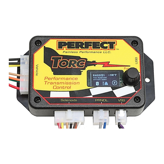
- Page 5 Kit Contents Photo: 66501 Included:(1) PERFECT TORC Module (1) 4L60/65E / 4L80/85E Transmission Harness (1) PERFECT TORC Vehicle Harness (1) USB communication cable (1) Spare 10amp ATO Fuse (1) 1 3/8” Firewall Grommet w/ ½”Hole (2) Mounting Screws (2) Mounting Bolts w/ Nuts (4) Hook &...
-
Page 6: Installation Steps
Installation Steps: Transmission Harness 1. Start by removing the system from the box and carefully laying it across a workbench or table. Take notice of the loomed transmission harness which contains the round transmission connector and vehicle speed sensor connector. These are the only two connections needed for both 4L60E (65E) or a 4L80E (85E) transmissions. - Page 7 Install Picture 2 – VSS (Vehicle Speed Sensor) Connector Figure 1 – Transmission Harness Connections on Transmission...
- Page 8 Installation Steps: Module Mounting & Connections THIS MODULE IS NOT INTENDED TO BE PLACED OR MOUNTED UNDER THE HOOD OR ANY PLACE EXPOSED TO EXSESSIVE HEAT OR MOISTURE. 1. The three TORC Module connectors from the transmission harness will need to be routed through the firewall.
- Page 9 Diagram 1 – 4L60E/65E Connection Diagram...
- Page 10 Diagram 2 – 4L80E/85E Connection Diagram...
-
Page 11: Vehicle Harness
Installation Steps: Vehicle Harness 1. The Vehicle Harness has a 16 pin connector that plugs into the left side of the TORC Module. See Figure 2 on page 8 for the connection. See Diagram 3 on page 15 for a diagram identifying the wires in this connector. 2. - Page 12 B. Black Wire(s) Labeled – “Module Ground” & “TPS Ground” Connection of these wires will depend on what type of throttle position sensor you are using: one that is part of an EFI system or one fitted to a carburetor or mechanically injected diesel engine. Electronic Fuel Injection Systems Splice both, “MODULE”...
- Page 13 C. Green Wire Labeled – “Throttle Position Sensor Signal” Connection of this wire will depend on what type of throttle position sensor you are using: one that is part of an EFI system or one fitted to a carburetor Electronic Fuel Injection Systems Connect this wire to the Throttle Position Sensor signal on a “Throttle-By- Cable”...
- Page 14 Identifying the Terminals of an Unknown Throttle Position Sensor This is a procedure for identifying the correct terminal connections of any potentiometer-style throttle position sensor (almost all three-terminal TP sensors). A DVOM or analog Ohmmeter is required. 1. Set the meter to resistance mode and set it to a scale that can read up to 10K or 20K Ohms (if it is not auto-ranging).
- Page 16 Optional Accessories within the TORC Module E. Tan Wire printed – “Speedometer Signal Output” We have provided an adjustable speed signal output on the tan wire on pin 12 of the vehicle connector that can be used to drive an electronic speedometer.
- Page 17 F. Yellow Wire printed – “Engine RPM Input” This is not a signal to operate a tachometer, but the same signal from your ignition system that operates a tachometer. The engine RPM signal input on the yellow lead (pin 7) can be connected to a digital tachometer output from an engine computer or the tachometer output from an MSD ignition or similar CDI (Capacitive Discharge Ignition) system, but NEVER to the coil outputs (coil negative stud) of a CDI system...
-
Page 18: Setting Up The Module
SETTING UP THE TORC MODULE Software Due to the growing number of PCs lacking a CD drive, the software is not included with this kit, but rather downloadable to a Windows PC from the 66501 product page on the Painless website. You will need the “Second Generation Software”... - Page 19 If needed, you can manually adjust TPS values by choosing “Adjust Idle” or “Adjust WOT” in the TPS setup menu. Once the TPS calibration procedure is completed, the values are permanently stored in the controller and will be active for every tune written. TPS values displayed within individual tunes are then irrelevant.
- Page 20 BUILT-IN DISPLAY The second generation built-in display of the Torc is easier to use and more intuitive than our previous module. It provides useful information, such as current speed, gear, transmission temperature, and TCC lock status, along with any fault messages. Using the menus, you’ll be able to access many of the same options found in Shiftware.
- Page 21 Home Screen Normal Mode Home Screen Enlarged Mode...
- Page 22 MAIN MENU Home Screen = Chooses the home screen as your default view. Info Screen = Shows current sensor values, replacing the home screen as default view. Info includes TPS voltage and percentage, battery voltage, commanded pressure in PSI, and engine RPM. Setup Menu = Use this menu to choose preliminary settings essential for operating the vehicle.
- Page 23 Speed Sensor = This menu allows you to choose your speed sensor type and configure its details such as speedometer drive gear teeth, driven gear teeth, and pulses per revolution. Rotating the knob in this screen changes the speed sensor type. Available speed sensor types will vary depending on the current transmission type.
- Page 24 TUNE MENU Shift Points = Sets the RPM at which shifts occur for all shifts. You will be presented with a menu showing 10% throttle, 40% throttle, and Wide Open Throttle. Under each is shown shift point RPM. You can adjust each throttle percentage individually.
- Page 25 Override = There are several options in this menu which are useful when troubleshooting. “Line Prs” can be used to override line pressure manually. Use this only if you were instructed to do so by a Painless technician. “TCC Sol” can be used to manually lock the TCC by holding the knob down. When released, the TCC will unlock.
-
Page 26: Shiftware Software
SHIFTWARE SOFTWARE Introduction Using the Shiftware software allows you to modify the way your Torc Transmission Control System behaves. You can customize shift-points as well as monitor and diagnose the Torc unit in real-time. Setup To create a calibration for the Torc module, it is best to start with one of the standard calibrations which are included with the software. - Page 27 Customize The main window is where all of the shift points and line pressure editing is done. The graph displays the up-shift and down-shift speeds in relation to throttle position for each shift. It also displays the line pressure & firmness curve in relation to throttle position.
- Page 28 If Select Pairs Together is enabled, then the corresponding down-shift point will be automatically selected along with the up-shift point. This can be turned off by clicking the checkbox on the right. You can select multiple points by holding CTRL while clicking the points or a range of points by holding SHIFT and clicking the two points on each end.
- Page 29 Once you have created your calibration, you can save the file to your hard drive or an external storage device. To save, click the Save button on the toolbar. Then, browse to the location where you want it saved and click Save. Use “Save As”...
- Page 30 Also note that torque converter slip at low speeds renders engine RPM values meaningless. It is usually desirable to have light-throttle shift points within a low RPM range. In this case, it is best to base light-throttle shift points on vehicle speed rather than engine RPM (as most auto manufacturers do).
-
Page 31: Error Messages
TROUBLESHOOTING ERROR MESSAGES WARNING! If the transmission does not begin to operate correctly within the first few feet of the road test, STOP immediately, check the for error messages, and troubleshoot. In some cases, just a few blocks of operation with low fluid pressure can destroy a transmission. - Page 32 TCC Solenoid overcurrent error An over-current condition was detected on the torque converter clutch pressure solenoid. A short circuit may be present in the solenoid circuit. The controller will attempt to disable the TCC solenoid until the ignition is turned off. TCC On/Off Solenoid overcurrent error An over-current condition was detected on the torque converter clutch solenoid.
- Page 33 TCC PWM Solenoid undercurrent error Current measured on the torque converter clutch pressure solenoid was too low, indicating that the solenoid circuit may be open. The controller will attempt to disable both TCC solenoids until the ignition is turned off. TCC Solenoid undercurrent error Current measured on the torque converter clutch pressure solenoid was too low, indicating that the solenoid circuit may be open.
- Page 34 TCC Solenoid circuit shorted TCC pressure solenoid resistance measured too low during the power-on solenoid check. The controller will attempt to disable the TCC solenoid until the ignition is turned off. Refer to the data display screen in the diagnostic menu to see the measured solenoid resistance.
- Page 35 TCC Solenoid circuit open TCC pressure solenoid resistance measured too high during the power-on solenoid check. The controller will attempt to disable the TCC solenoid until the ignition is turned off. Refer to the data display screen in the diagnostic menu to see the measured solenoid resistance.
- Page 36 Checksum error in table A Checksum error has been found in the calibration table. It will also disable saving Setup Menu changes and disable the tuning menu. Connect the controller to a PC and load a calibration using Shiftware. Torque Converter Clutch Slip Error Torque converter clutch slip detected when fully engaged.
- Page 37 Painless Performance Limited Warranty and Return Policy Chassis harnesses and fuel injection harnesses are covered under a lifetime warranty. All other products manufactured and/or sold by Painless Performance are warranted to the original purchaser to be free from defects in material and workmanship under normal use.
Need help?
Do you have a question about the PERFECT TORC and is the answer not in the manual?
Questions and answers