
Related Manuals for Ahlborn ALMEMO 8390-2

Summary of Contents for Ahlborn ALMEMO 8390-2
- Page 1 Operating instruction Universal transmitter ® ALMEMO 8390-2 V1.0 13.11.2003 ® ALMEMO 8390-2...
-
Page 2: Table Of Contents
Table of contents Operating istruction Universal transmiter ® ALMEMO 8390-2 With supplementary reference to the ALMEMO® Manual Table of contents page INTRODUCTION Functions Operating controls PUTTING INTO SERVICE POWER SUPPLY Power supply via the mains adapter DC voltage supply (option U) Sensor supply Data safeguarding, reinitialization CONNECTING THE TRANSDUCERS... - Page 3 Table of contents 6.3.2 Cyclic measuring point scan 6.3.3 Output formats for measured value lists 6.3.4 Manual data output Averaging 6.4.1 Smoothing out measured values by means of a sliding average 6.4.2 Averaging mode 6.4.3 Averaging over the time from start to stop 6.4.4 Averaging over single measurements 6.4.5...
-
Page 4: Introduction
Functions 1. INTRODUCTION ® The universal measuring instrument ALMEMO 8390-2 is a new member in our family of unique measuring devices - all equipped with Ahlborn GmbH’s paten- ® ® ted ALMEMO connector system. The intelligent ALMEMO connector offers decisive advantages when connecting sensors and peripherals because all pa- rameters are stored in an EEPROM on the connector itself;... -
Page 5: Functions
Functions SENSOR PROGRAMMING ® The measuring channels are automatically programmed via the ALMEMO sen- sor connectors. However, the user can easily supplement or modify this pro- gramming via the keypad or via the interface. Measuring ranges Appropriate measuring ranges are available for all sensors with a non-linear characteristic, e.g. - Page 6 Functions decimal point position can be set by means of the exponent function. By setting to zero and entering the nominal value the scaling values can be calculated au- tomatically. Limit values and alarm Per measuring channel two limit values can be set (1 maximum and 1 mini- mum).
- Page 7 Functions out, or deleted from memory. Average value of a channel Averaging can be performed per selected channel for the purposes of signal smoothing, either over a certain period or over single measurements. Volume flow measurement For all flow sensors not only the functions for averaging are provided but also functions for entering the cross-section and diameter of ventilating channels and for calculating the volume flow.
- Page 8 Functions a conversion rate of either 2.5 or 10 measuring operations per second. It is al- so possible to output all measured values to the interface. Control outputs It is possible via the interface to individually address up to four external output relays and one analog output.
-
Page 9: Operating Controls
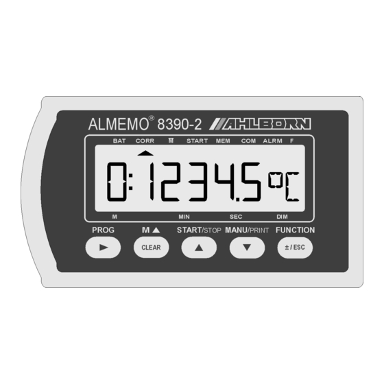
Operating controls 1.2 Operating controls ( 1 ) Front: CORR START ALARM F (1) LCD display (a) Symbols for operating states Battery voltage < 7 V ▲ CORR Measured value correct. ▲ Averaging ▲ START Measuring operat. started ▲ COM Measured value output ▲... - Page 10 Operating controls (2) FUNCTION KEYS PROG, ▲ ▼, +/-, Input of programming parameters PROG, CLEAR Clear data, set measured value to zero PROG, ▼, PROG Adjust measured value ▲ Select measured value, measuring point START/ STOP Start and stop a measuring operation MANU/ PRINT Manual measuring point scan, data output...
-
Page 11: Putting Into Service
Putting into service 2. PUTTING INTO SERVICE 1. Connect transducer to socket M0 (3); (see Section 4). 2. Ensure the power supply is connected via the mains adapter; (see Sections 3.1, 3.2). 3. Displaying the measured values Select MEASURED VALUE function by pressing the key M▲ (2). Select measuring channels by pressing key M▲, read out the measured values;... -
Page 12: Power Supply
Power supply 3. POWER SUPPLY As power supply there are the following possibilities : Mains adapter 12 V / 200 mA ZB 1012-NA1 DC voltage supply, 7 to 13 V DC DC voltage supply, 9 to 30 V DC, electrically isolated OA 8390-U 3.1 Power supply via the mains adapter On the rear of the device there is the socket (5) for connecting an external po-... -
Page 13: Connecting The Transducers
To withdraw the connector, both these levers must be pressed in at the sides. 4.2 Measuring inputs and additional channels Measuring instrument ALMEMO 8390-2 incorporates an input socket M0 (1), to ® which initially measuring channel M0 is assigned. ALMEMO sensors can, however, if necessary, provide up to four channels. - Page 14 Connecting the transducer On the measuring instrument this gives the following channel assignment : continuous sequencing numbered in decimal form (default) chann. 4 chann. 3 chann. 2 chann. 1 8390-2 Sensors combined within one connector and sensors with their own power supply, however, are electrically interconnected and must therefore be operated in isolation.
-
Page 15: Display And Keypad
Display and keypad 5. DISPLAY AND KEYPAD 5.1 Display ® The display (1) on measuring instrument ALMEMO 8390-2 comprises an LCD with 6½ x 7-segment characters, two 16-segment characters, a battery symbol, and seven arrows to indicate the operating status. CORR START COM ALARM F... - Page 16 Display and keypad Special operating states Segment test for display This is performed automatically each time the device is switched ON. Supply voltage: below 7 volts: symbol lights up 1:L o b A t below 6 volts: Checksum error during C A L E r r ...
-
Page 17: Function Selection And Function Activation
Display and keypad 5.2 Function selection and function activation ® Measuring instrument ALMEMO 8390-2 provides a wide variety of functions for controlling measuring sequences, for acquiring, averaging, monitoring, and saving measured values, for outputting data to various peripheral equipment, and for scaling, adjusting, and correcting sensors, etc.. Since these functions will not be needed by the normal user all at once, they can be activated in va- rious ways on an application-specific basis. - Page 18 Display and keypad Value Abbrev. Memory Functions Activation 01.12.99 DA Hold down FUNCTION key Date Device first time it is pressed Un 9600 BR Hold down FUNCTION key Baud rate, output format Device first time it is pressed 00 A Hold down FUNCTION key Device address Device...
-
Page 19: Keypad
Display and keypad 5.3 Keypad Each of the keys (2) initially has the normal function noted above it : Function Normal Eingabe PROG Programming M ▲ CLEAR Select measured value and measuring point START / ▲ Start and stop measuring point scanning STOP ▼... -
Page 20: Data Input
Display and keypad 5.4 Data input Numeric parameters are programmed as follows : FUNCTION Select the desired function by pressing the FUNCTION key PROG Start programming by pressing the PROG key. The front digit flashes and can now be changed. ▲... -
Page 21: Measuring Operations
Measuring operations 6. MEASURING OPERATIONS ® Measuring instrument ALMEMO 8390-2 provides the following options for measured data acquisition : 1. Continuous measuring point scanning of all active measuring points (see Section 6.1 and Manual, Section 6.5.1.3) Representation of a selectable measuring point in the display Measured value output to an analog output (see Chapter 8). -
Page 22: Maximum And Minimum Value Memories
Measuring operations 6.1.2 Maximum and minimum value memories From the measured values acquired per measuring point the highest and the lowest values are determined and saved for each. To display these extremes first the desired channel must be set and then the MAXIMUM VALUE or MINI- MUM VALUE function selected by pressing the FUNCTION key. -
Page 23: Sensor Adjustment, Zero-Point, And Gain
Measuring operations When the PROG key is pressed in function ´CL´ the measured value 000.0 flashes; when the CLEAR key is then pressed, the measured value is saved as base value and set to zero. So long as the deviation from the base value is shown (rather than the actual measured value), the CORR arrow appears in the display. -
Page 24: Entering A Setpoint
Measuring operations In this case the corrected value is not saved to the connector’s EE- PROM but only to the RAM; i.e. once the device is switched off, then the next time it is switched on, this will be restored to its origi- nal value. -
Page 25: Cold Junction Compensation
Measuring operations 1. Set the locking mode to level 4 or 3 (e.g. by switching on with the PROG and FUNCTION keys held down, see above) 2. Select meas. value and apply the calibration value 1: 0 9 8.7 °C (e.g. -
Page 26: Atmospheric Pressure Compensation
Measuring operations 6.2.5 Atmospheric pressure compensation Some measured variables depend on the ambient atmospheric pressure (see Section 7.7, measuring range list ´with PC´) with the effect that pronounced de- viations from normal pressure (1013 mbar) may lead to measuring errors. e.g. -
Page 27: Measuring Point Scans And Data Output
Measuring operations 6.3 Measuring point scans and data output Measuring point scans can be used to acquire and then evaluate data from all active measuring points at particular times (for the purposes e.g. of averaging, outputting to the interface, or saving to memory). A measuring point scan can be initiated at any time-of-day either manually or automatically by a cycle. -
Page 28: Output Formats For Measured Value Lists
Measuring operations START/STOP To start a cyclic measuring point scan: key: cycle programmed To stop automatic measuring point scanning press the START/STOP key again. The ´START´, ´COM´, and ´MEM´ lights go out again.. START/STOP To stop a cyclic measuring point scan : key: 6.3.3 Output formats for measured value lists Both for manual and for cyclic measuring point scans (see Sections 6.3.1/2) the measured values are output as measured value lists in a wide variety of output... -
Page 29: Manual Data Output
Measuring operations 6.3.4 Manual data output In all functions selected by pressing the FUNCTION key, the function values can, by pressing the MANU/PRINT key, be output to a printer or computer, partly as ta- bles and with the following printout formats : Function Abb Printout MH MAXIMUM:... -
Page 30: Averaging
Measuring operations 6.4 Averaging The average value of the measured value is required for various applications : e.g. the average flow velocity in a ventilation channel smoothing of a widely fluctuating measured value (e.g. wind, pressure etc.) hourly or daily average values of weather data (temperature, wind etc.) as above, for consumption values (current, water, gas, etc.) The average value of a measured value is obtained by adding together a se-... -
Page 31: Averaging Over The Time From Start To Stop
Measuring operations ® If a sensor with an ALMEMO connector is connected, the following modes can be set by pressing keys PROG, ▲ ▼, PROG : Function Display No averaging: - - - - Continuous averaging from start to stop (see Section 6.4.3) C o n t or over single measurements, if not started (see Section 6.4.4): C Y C L... -
Page 32: Averaging Over Single Measurements
Measuring operations CORR 2. Start averaging by pressing the START/ STOP 1: 1 1.5 6 The average value is automatically deleted with each new start ! In the display the ´START´ and ´´ arrows light up. All measured data can be saved to memory or output 3. -
Page 33: Volume Flow Measurement
Measuring operations 6.4.5 Volume flow measurement To determine the volume flow VF in ventilating channels multiply average flow velocity ¯ v by cross-section area CS.: VF = ¯ v 0.36 VF = m /h, ¯ v = m/s, CS = cm For approximate air volume measurements at air vents and gratings the aver- age flow velocity can be determined by means of time-based averaging. -
Page 34: Cyclic Averaging
Measuring operations Entering the cross-section The cross-section area CS can be entered in the ´Flow´ channel either directly in the ´CS´ function up to a maximum of 32000 cm2 or as diameter in the ´DN´ function up to a maximum of 2000 mm; (see Section 5.4). When the function channel ´Flow´... -
Page 35: Sensor Programming
Sensor programming 7. SENSOR PROGRAMMING ® ® Since on ALMEMO devices all sensor programming is stored in the ALMEMO connector, the user will not normally need to reprogram. Programming will only be necessary e.g. if sensor errors are corrected, if your own sensors are sca- led, or if certain limit values are stipulated;... -
Page 36: Limit Values
Sensor programming Locking mode function ´LM´ FUNCTION 1:0 0 0 5 Select by pressing key: ... Enter as per Sec. 5.4 In the display, in front of the locking mode, you should see output function, ele- ment flags and multiplexer position - assuming these have been programmed (see Manual, Section 6.10.2/3/4). -
Page 37: Scaling, Decimal Point Setting
Sensor programming Sensor adjustment To simplify the correction of sensors for zero-point and if necessary also for gain, the MEASURED VALUE function includes a special function which per- forms this adjustment automatically (see also Section 6.2.2). 7.5 Scaling, decimal point setting To display the electrical signal of a sensor as measured value in its physical si- ze, it is nearly always necessary to perform decimal point shift, zero-point cor- rection, and multiplication with a factor. -
Page 38: Changing The Units
Sensor programming 7.6 Changing the units Per measuring channel the default units for the measuring range in question can be replaced with any two-character units; (see also Manual, Section 6.3.5). All upper-case and lower-case letters, special characters °, °, Ω, %, [, ], *, -, =, ~, and space (_) can be used. - Page 39 Sensor programming After pressing and holding down the PROG key for a short while the abbrevia- ted designation for the measuring range appears in the display and starts ▲ und ▼, all possible measuring ranges can flashing. Now, by pressing keys be selected in the order listed in the table below.
- Page 40 Sensor programming Sensor / connector Display Transducer Measuring range Units FrEq ZA 9909-AK 0... 25000 Frequency PULS ZA 9909-AK 0... 65000 Pulses Digital input ZA 9000-EK2 0.0... 100.0 diGi ZA 9919-AKxx -65000... +65000 Digital interface Ir 1 ZA 9000-FS 0.0... +200.0 °C Infrared 1 Ir 2...
- Page 41 Sensor programming Sensor / connector Display Transducer Measuring range Units S[P] ZA 9909-AK2 0... 65000 Pulses / print cycle of Mb1 Alrn beliebig Alarm value of channel Mb1 q/dt Therm. coeff. M(Mb1)/M(M03) ZA 9000-FS UbGt Wet bulb globe temperature ZA 9000-FS °C MESS Measured value of Mb1...
-
Page 42: Analog Output
Analog output 8. ANALOG OUTPUT For the analog registration of the selected measuring point you can, to socket A1, connect either an analog output cable ZA 1601-RK (see Manual, Section 5.1.1) without electrical isolation or a relay trigger analog adapter ZA 8000-RTA (see Manual, Section 5.1.3) with electrically isolated analog output. -
Page 43: Device Programming
(see Section 9.2). 9.1 Date and time-of-day The ALMEMO 8390-2 incorporates an integrated clock with date and time-of- day for logging measuring times. This clock is not buffered, with the effect that date and time-of-day must be set anew each time you switch on. -
Page 44: Device Address And Networking
Device programming or 115.2 kbaud (paying attention not to exceed the maximum baud rate for the interface module !). BAUDRATE function ´BR´ U n 9 6 0 0 Select by pressing the FUNCTION key For example : Output to interface ´U´, in ´side-by-side´ format, 9600 baud To enter this information press the PROG key twice, then set the baud rate by ▲... -
Page 45: Trouble-Shooting
Trouble shooting 10. TROUBLE - SHOOTING ® ALMEMO 8390-2 measuring instruments can be configured and programmed in many versatile ways. These measuring instruments are suitable for con- necting a wide variety of very different sensors, additional measuring instru- ments, alarm signaling devices, and peripheral equipment. Given these nu- merous possibilities the devices may in certain circumstances not behave quite as expected. -
Page 46: Electromagnetic Compatibility
Electromagnetic cmpatibility Test data transmission by means of a terminal (AMR-Control, WIN- Control, WINDOWS-Terminal) : Address the device using its as- signed device number Gxy (see Manual, Section 6.2.1), Check the programming by means of P15 (see Manual, Section 6.2.3), Test the transmit line by entering a cycle with command ´Z123456´... - Page 47 Appendices Technical data (see also Manual, Section 2.2) ® Measuring inputs : 1 ALMEMO socket ® for ALMEMO flat connector Channels : 4 channels / sensor maximum (measuring and function channels, depending on sensor type) A/D converter : delta-sigma, 16-bit resolution Measuring rate : 2.5 / 10 measuring operations per second continuous on all channels...
- Page 48 Appendices Product overview Order No. ® Universal measuring instrument ALMEMO 8390-2 1 input, maximum 4 channels, with LCD and 5 keys, output for interface or analog output MA 8390-2 Option HS: Adapter for top-hat rail mounting OA 2290-HS Option U : DC voltage supply, electrically isolated, 9 to 30 V DC OA 8390-U Option I:...
- Page 49 Appendices Index Keyword Section Page Additional channels Analog output - start / end Atmospheric pressure compensation 6.2.5 Averaging Averaging mode 6.4.2 Averaging over cyclic measuring point scans 6.4.6 Averaging over manual single measurements 6.4.4 Averaging over time 6.4.3 Base value Baud rate Changing the units Cold junction compensation...
- Page 50 Appendices Keyword Section Page Final value adjustment of force transducers 6.2.3 Function abbreviations 1.2, 5.2 9, 17 Function activation Function display 5.1, 5.2 15, 17 Function keys 1.2, 5.3 9, 19 Function printouts 6.3.4 Function selection Functions 6.2.2 Gain adjustment Gain correction Hysteresis Introduction...
- Page 51 Appendices Keyword Section Page Sensor adjustment 6.2.2 Sensor programming Sensor supply voltage Service address Setting the measured value to zero 6.2.1 Sliding average 6.4.1 Smoothing of measured values 6.4.1 Smoothing, measured value 6.4.1 Start and stop a measuring operation 6.3.2 Supply voltage monitoring Table of contents Technical data...
- Page 52 Appendices Your contact partners ® ALMEMO 8390-2...
Need help?
Do you have a question about the ALMEMO 8390-2 and is the answer not in the manual?
Questions and answers