Table of Contents
Advertisement
Quick Links
Advertisement
Table of Contents

Related Manuals for Zap ZAPVAN SHUTTLE 2010


Summary of Contents for Zap ZAPVAN SHUTTLE 2010
- Page 2 FAILURE TO COMPLY WITH THE STANDARDS OUTLINED IN THIS MANUAL COULD RESULT IN FIRE AND/OR SERIOUS INJURY. ZAP IS NOT LIABLE FOR ANY DAMAGE OR INJURIES CAUSED BY UNSAFE OR FAULTY REPAIRS, OR ALTERATIONS. ANY REPAIRS MADE TO THIS PRODUCT BY UNAUTHORIZED SERVICE TECHNICIANS ARE THE SOLE RESPONSIBILITY OF THE OWNER.
- Page 3 We are looking for dealers. If you are interested please contact us! We are proactive, not perfect. If you have ideas, we want to hear from you. If you can help spread the word about ZAP, please do so.
-
Page 4: Table Of Contents
Introduction of Devices Chapter 6 Service and Maintenance and Control Mechanism 1. Cleaning and maintenance........30 1. Position of switches and ZAP Registration Card ........55 control levers in the cabin......11 2. Routine maintenance..........31 3. Regular maintenance..........31 2. Keys, doors and windows......17 3. -
Page 5: General Information
2010 Owner and Operator’s Manual General Information 1. Overall Dimensions... -
Page 6: Table Of Performance, Structure
2010 Owner and Operator’s Manual General Information 1. Table of performance, structure and specifications for entire vehicle 1.1 Table of Dimension and Mass parameters : ZAPVAN Shuttle Item flat head 4×2 driving with rear wheels Type 4 seats 138.4” Length 54.9”... - Page 7 2010 Owner and Operator’s Manual General Information 1.2 Table of performance parameters Item ZAPVAN Shuttle Minimum turn radius 177.2” Ground clearance 6” Approach angle° Trafficability Departure angle° parameters Front overhang 30.7” Rear overhang 28” Camber angle° 2±15´ Kingpin inclination° Steering parameter Kingpin caster°...
- Page 8 2010 Owner and Operator’s Manual General Information 1.3 Table of Structure and Specifications (cont’d) Item ZAPVAN Shuttle Type of tires Meridian tire Tire specification 155 R12 LT 6PR wheel rim 4.5B×12 Wheel No-load: 200 Kpa (31 PSI) Front Kpa(PSI) Tire pressure Full-load: 200 Kpa (31 PSI) (COLD) No-load: 200 Kpa (31 PSI)
- Page 9 2010 Owner and Operator’s Manual General Information 1.3 Table of Structure and Specifications (cont’d) Item ZAPVAN Shuttle The connection type of wire cathode ground strap connection Rated voltage of circuit Battery 12V/36 Ah Hoot ≥93dB (the position of 2m distance) Washer intermittent washing and wiping with motor Motor auto-return, intermittent and two-speed (no-load 45times/...
-
Page 10: Vehicle Marking
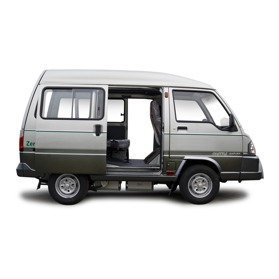
3. Branding life, safety provisions and may even be Body surface has the ZAP logo in font and back. illegal by state law. Vehicle damage and ZAPVAN and Zero Emissions are also branded... -
Page 11: Vehicle Maintenance
2010 Owner and Operator’s Manual Tire pressure (Cold conditions) kPa (PSI) 3. Vehicle Maintenance Item No-Load Full-Load In order to maintain the vehicle in good running 200Kpa 200Kpa condition, please service the vehicle according to Front (31 PSI) (31 PSI) this manual. -
Page 12: Introduction Of Devices And Control Mechanism
2010 Owner and Operator’s Manual Introduction of Devices and Control Mechanism 1. Switches and Control Levers in the Cabin 1. Combination switch (for turn signal lights, headlights and dimmer) 2. Combination instrument panel 3. Wiper and washer switches 4. Odometer 5. - Page 13 2010 Owner and Operator’s Manual Introduction of Devices and Control Mechanism As shown in the picture, when turning the switch 1. Ignition switch and steering lock When the key is turned to this position, all clockwise, the right turn signal light is on; In electrical power systems of the vehicle are reverse, the left turn signal light is on.
- Page 14 2010 Owner and Operator’s Manual Introduction of Devices and Control Mechanism 5. Direction select switch 3. Windshield Washer There are three positions of the direction al Lift the switch toward the direction of the arrow select switch, all of which can change the driving and cleaning fluid will spray on the windshield.
- Page 15 2010 Owner and Operator’s Manual Introduction of Devices and Control Mechanism 4. Combination instrument 8. High beam Indicator light The indicator light is on when high beam lights are activated. 9. Auxiliary battery charge light - Red This warning light turns on when voltage of Auxiliary battery is below 11.8V and ignition switch is in “ON”...
- Page 16 2010 Owner and Operator’s Manual Introduction of Devices and Control Mechanism 5. Multi-functional display Auxiliary battery voltage: two digits + P + one Code Definition digit, for example: 13P5 means that Auxiliary E-02 IGBT malfunction battery voltage is 13.5 volts at present Electric power combination battery: Two digits E-03 motor over-current...
- Page 17 2010 Owner and Operator’s Manual Introduction of Devices and Control Mechanism E-12** Contactor failure If direction select switch will periodically beep, and the charge indicator 3. Format and content of display: is in shift “R” or shift “F” when starting vehicle , light will be on as well At this time, you should Accumulation of all mileage:three digits with one electric control system has nothing to export but...
-
Page 18: Keys, Doors And Windows
2010 Owner and Operator’s Manual Introduction of Devices and Control Mechanism 2. Keys , doors and windows Keys Each vehicle is equipped with two identical keys which unlock all doors and compartments. Inside the door (as shown in Figure 2) NOTE 1. -
Page 19: Seats
2010 Owner and Operator’s Manual Introduction of Devices and Control Mechanism 3. Seats 2. Folding the seat down Lift up the angle adjuster handle on the outer side of the seats. Then loosen the rear anchor Front seats butterfly bolt or pull the locking handle when The angle adjuster, mounted on the outer side of seatback contacts the cushion. -
Page 20: Safety Belts
2010 Owner and Operator’s Manual Introduction of Devices and Control Mechanism 4. Safety belt Adjust the seat and sitting posture until it is This Van is equipped with three-point Emergency comfortable, and fasten the waist belt above NOTE Locking Retractor (hereafter called ELR) safety thighs (under the pelvis). - Page 21 2010 Owner and Operator’s Manual Introduction of Devices and Control Mechanism Fasten the safety belt Determine if the metal shackle is in correct angle Protect the safety belt from contamination and then lengthen or shorten the belt to tighten by contact with chemicals (especially the or loosen it.
-
Page 22: Other Devices
2010 Owner and Operator’s Manual Introduction of Devices and Steering Mechanism 5. Other Devices Adjustment 4. Safety handrail Adjust the internal rearview mirror so that driver 1. External rearview mirror has a clear rear field of vision. WARNING! While driving, do not attempt to adjust the internal &... - Page 23 2010 Owner and Operator’s Manual Introduction of Devices and Steering Mechanism 6. Ash tray Pull out the ashtray when in use. Press the cover tab and pull it out empty contents and clean. WARNING! To avoid fire, the ashtray should not be used as a junk receptacle.
- Page 24 2010 Owner and Operator’s Manual Introduction of Devices and Steering Mechanism 8. Other Control Devices 9. Pedals The battery array is charged by the on board charger. Operation sequence is as below: Parking Brake Lever Pull the lever up to activate the parking brake. The •Connect the charger to the AC power higher the lever is pulled up the more braking supply.The AC indicator light on charger is on.
-
Page 25: Driving Suggestions
2010 Owner and Operator’s Manual Driving Suggestions I. Driving Operation 3. Running accelerator completely and press the brake •Adjust the driving direction by controlling the pedal. In this case the controller activates steering wheel. “strong regenerate braking”, and you will feel 1. -
Page 26: Economical Driving Suggestions
2010 Owner and Operator’s Manual Driving Suggestions 3. Economical Driving Suggestion descending driving. WARNING! To achieve economical driving, always service, •When the vehicle is moving on a slope, the and maintain the vehicle periodically to keep it in mechanical brake takes priority, and the motor Pull manual brake tight when parking. -
Page 27: Emergency Conditions
2010 Owner and Operator’s Manual Emergency Conditions I. Vehicle Starting Failure slowly steer the vehicle to the roadside and NOTE consult your service technician. 1. Check Charging You should routinely brush off dirt and dust The vehicle has a charging check function. Check If the steering system is completely out of control, from the radiator of the on-board charger, the charge connect from the AC to source. -
Page 28: Deflated Tires
2010 Owner and Operator’s Manual Emergency Conditions 6. Deflated Tires If the wheel is equipped with an ornamental cover, pry off the cover with a straight screwdriver. WARNING! Jack up positions of the hoisting jack: In case of a flat tire while running, do not Front axle apply hard braking, as the vehicle could go Jack up the underside of lower trailing arm with... - Page 29 2010 Owner and Operator’s Manual Emergency Conditions WARNING! NOTE To avoid vehicle damage and personal Do not apply machine oil or grease on injury: wheel nut, otherwise it may become loose during driving. Do not place the hoisting jack in positions other than those specified.
-
Page 30: Emergency Towing
2010 Owner and Operator’s Manual Emergency Conditions 7. Emergency Towing Towing trailing Precautions for using the draw ring: It is suggested to schedule vehicle towing only by If it is impossible to start the vehicle, attach a ·•Make sure the draw ring is secure. a qualified towing service organization. -
Page 31: Service And Maintenance
2010 Owner and Operator’s Manual Service and Maintenance I. Cleaning and Maintenance MAINTENANCE OF SAFETY BELT WARNING! •Keep the safety belt dry and clean. •Clean belts only by neutral soapy water and 1. External Cleaning and Maintenance for Wet brakes may lead to an accident. Wet warm water. -
Page 32: Routine Maintenance
2010 Owner and Operator’s Manual Service and Maintenance When cleaning the inside of the vehicle door, door SAFETY CHECK NOTE sill, sole bar and other parts, the drain hole should •Check that lights, instruments, wipers, hand be unobstructed. brake and foot brake, wheels, steering, drive Before repairing electrical equipment, please •Keeping garage dry. - Page 33 2010 Owner and Operator’s Manual Service and Maintenance Tale of regular inspection and maintenance: Intercal (months) Breaking- in period Distance (m) Check and Maitenance Items 1000 3000 6000 12000 18000 24000 Accelerator, shaft, check, adjustment, lubrication or replacement J.T.R.G Gear box lubricant Transmission shaft:inspect Reducer lubricant Bolts for connecting: Fastening...
- Page 34 2010 Owner and Operator’s Manual Service and Maintenance Tale of regular inspection and maintenance: Intercal(months) Distance(km) Check and Maitenance Items 1000 3000 6000 12000 18000 24000 Inspect brake pipe;Inspect,adjsut and lubricate the performance of parking brake and pedal brake;Inspect and adjust the free stroke of J.T.R brake pedal.
-
Page 35: Requirement For Regular Maintenance
2010 Owner and Operator’s Manual Service and Maintenance 4. Requirement for Regular Maintenance 2. DC/DC Converter 3. AC Asynchronous Motor and Controller This converts 72VDC which comes from power The AC asynchronous motor (Fig.1) and controller batteries to 12VDC by DC/DC conversion and supplies (Fig.2) are the power equipment of the vehicle, 1. - Page 36 2010 Owner and Operator’s Manual Service and Maintenance 4. Inspect and Clean The Accumulator NOTE WARNING! Keep battery surface and binding post clean. Apply lubricating grease onto joints to prevent from rust If the controller stops due to various Accumulator will generate combustible...
- Page 37 2010 Owner and Operator’s Manual Service and Maintenance Fuse box (Equiped on left side under IP) please replace with a new one of the same type. check the connection of following parts: • ball pin of steering linkage • engagement of steering gears and racks, •...
- Page 38 2010 Owner and Operator’s Manual Service and Maintenance the brake booster, then depress the brake pedal to 9 teeth, the travel of parking brake meets the again until the resistance increases (push rod of requirement, otherwise it is necessary to adjust. the brake booster contacts with When adjusting, disassemble the plate of tea table, release the handle of parking brake, unscrew...
-
Page 39: Solutions For Malfunctions
2010 Owner and Operator’s Manual Solutions for Malfunctions Chapter 7 Solutions for Frequent Malfunctions 1. Rear Axle Malfunctions Trouble designation Trouble description Remedy Oil seal is damaged or worn Replace Oil leaks There is too much oil Adjust oil level Air plugs are blocked Clean (Constant noise) gear oil is deteriorated or contains water... -
Page 40: Steering, Suspension, Wheel And Tire
2010 Owner and Operator’s Manual Solutions for Malfunctions 2. Steering, Suspension, Wheel and Tire Malfunctions Trouble designation Trouble description Remedy Tires are unmatched Replace Tire pressure is improper Adjust tire pressure to specified value Front spring is damaged or shortened due to plastic deformation Replace spring Wheels do not run Evenness of radial tire (referring to lateral oscillating range) exceeds... - Page 41 2010 Owner and Operator’s Manual Solutions for Malfunctions 2. Steering, Suspension, Wheel and Tire Malfunctions (cont’d) Trouble designation Trouble description Remedy Tire is with bulge or damaged Replace tire Evenness of radial tire (referring to change in radial rigidity) exceeds Replace tire limit value Wheels’...
- Page 42 2010 Owner and Operator’s Manual Solutions for Malfunctions 2. Steering, Suspension, Wheel and Tire Malfunctions (cont’d) Trouble designation Trouble description Remedy Tire pressure is insufficient Charge the tire to specified pressure Ball pin of steering linkage or balljoint of left and right lower trail- Replace ball pin of steering linkage or lower trailing ing arm jams Steering is difficult...
- Page 43 2010 Owner and Operator’s Manual Solutions for Malfunctions 2. Steering, Suspension, Wheel and Tire Malfunctions (cont’d) Trouble designation Trouble description Remedy Tires are unmatched or charged unevenly Replace tire or charge it to specified pressure Globe joint of lower trailing arm or ball pin of steering linkage was loose Replace suspension arm or ball pin of steering linkage Front shock absorber or fitting piece goes wrong.
- Page 44 2010 Owner and Operator’s Manual Solutions for Malfunctions 2. Steering, Suspension, Wheel and Tire Malfunctions (cont’d) Trouble designation Trouble description Remedy Vehicle is overloaded or load on one side is extremely heavy. Check loading status Suspension is pressed to Spring holder of front shock absorber is sealed off Replace front shock absorber the bottom.
-
Page 45: Braking Malfunctions
2010 Owner and Operator’s Manual Solutions for Malfunctions 3. Braking Malfunctions Trouble designation Trouble description Remedy Friction lining is damaged Replace brake shoe or brake pad Braking system is oil leaking. Find out leaked part and repair it Malfunctions of brake master cylinder Repair or replace brake master cylinder Brake height of brake pedal is too low... - Page 46 2010 Owner and Operator’s Manual Solutions for Malfunctions 3. Braking Malfunctions (cont’d) Trouble designation Trouble description Remedy Friction lining is contaminated with oil stains or grease Replace brake shoe Malfunctions of self-adjustment mechanism of rear wheel brake Repair or replace self adjustment mechanism Brake force is uneven Brake drum or brake disc is out of round Replace brake drum or brake disc...
-
Page 47: Malfunctions Of Power System
2010 Owner and Operator’s Manual Solutions for Malfunctions 4. Malfunctions of power System Fuse(F8) of 30A blows out. Check fuse When the ignition The relay, which guide the DC/DC conversion and output has check the relay switch is in position failed “ACC”... -
Page 48: Malfunctions Of Electric Controlling System
2010 Owner and Operator’s Manual Solutions for Malfunctions 6. Malfunctions of Electric Cooling System Trouble Code Trouble description Remedy E-01 Overvoltage of generatrix Turn the ignition switch to the position “OFF” and then restart the vehicle after the system resetting. If the problem occurs repeatedly , please have the controller checked and repaired. -
Page 49: Malfunctions Of Lights, Instruments, Switches And Indicating Lights
2010 Owner and Operator’s Manual Solutions for Malfunctions 6. Malfunctions of Electric Cooling System (cont’d) Trouble Code Trouble description Remedy Dimish the load of the vehicle E-08 Overload of temperature sensitive relay Clean the feculency of radiator of the controller Turn the ignition switch back to position “OFF”... - Page 50 2010 Owner and Operator’s Manual Solutions for Malfunctions 7. Malfunctions of lamps, instruments, switches and indicating lamps 1) MALFUNCTIONS OF FRONT HEAD LIGHTS Trouble designation Trouble description Remedy Lamps are damaged Check lamps Malfunctions of front head lamp switch Check front head lamp switch Front head lamps are off.
- Page 51 2010 Owner and Operator’s Manual Solutions for Malfunctions 7. Malfunctions of lamps, instruments, switches and indicating lamps (cont’d) 3) MALFUNCTIONS OF TURN SIGNAL LAMPS AND EMERGENCY ALARM LAMPS Trouble designation Trouble description Remedy Lamps on the side with high flashing frequent are damaged Check lamps Lamp arrangement is incorrect Check lamps...
- Page 52 2010 Owner and Operator’s Manual Solutions for Malfunctions 7. Malfunctions of lamps, instruments, switches and indicating lamps (cont’d) 4) MALFUNCTIONS OF BACKUP LIGHT Trouble designation Trouble description Remedy Backup light is off. Lamps are damaged Check lamps Fuse (F11) of backup light blows out Check fuse, replace if necessary (In case of replacement, check for short circuit) Malfunctions of backup light switch...
- Page 53 2010 Owner and Operator’s Manual Solutions for Malfunctions 6) MALFUNCTIONS OF ALARM LIGHTS FOR BRAKING FLUID LEVEL AND PARKING BRAKE Lamp for combination instrument is damaged Check lamp Check fuse (In case of replacement, check for short Fuse (F11) blows out circuit) When braking fluid Malfunctions of combination instrument circuit...
- Page 54 2010 Owner and Operator’s Manual Solutions for Malfunctions 7) WIPER AND WASHER MALFUNCTIONS Fuse (F6) for wiper (washer) blows out Check fuse (In case of replacement, check for short circuit) Wiper will not work or Malfunctions of wiper motor Check wiper motor can’t return to its original position.
-
Page 55: Specification And Capacity Of Lubricant, Lubricant Grease And Braking Fluid
2010 Owner and Operator’s Manual Oil, Fluid for Vehicle and Electrical Values of Complete Vehicle 7. Oil, Fluid for Vehicle and Circuit Diagram of Complete Vehicle 1) SPECIFICATION AND CAPACITY OF LUBRICANT, LUBRICANT GREASE AND BRAKING FLUID ITEM STANDARD (Recommended) CAPACITY (Liters) REMARK Gear-box lubricating oil... -
Page 56: Zap Registration Card
REGISTRATION CARD (Not returning this card will not void the original 6-months limited warranty.) 8. What most influenced your decision to purchase a ZAPVAN? 1. Name & Address: * Title Mrs. Miss Factors (check all that apply): Received as a gift Advertisement Brand name Friend's/relative's recommendation... - Page 57 Own an Apple/Macintosh Speak Spanish Computer Own a CD-ROM Drive Thank you for filling in this registration card. Please tear off along the doted line and mail to the following address: ZAP 501 Fourth Street, Santa Rosa, CA 95403 USA.
Need help?
Do you have a question about the ZAPVAN SHUTTLE 2010 and is the answer not in the manual?
Questions and answers