Table of Contents
Advertisement
Quick Links
OPERATION & MAINTENANCE MANUAL
TELELIGHT
TL-90 LIGHTING TOWER
The information in this manual is subject to change without prior notice.
SMC Light & Power
SMC Light & Power a division of Arc-Gen Ltd.
Belchmire Lane, Gosberton, Lincs PE11 4HG UK
Tel: 44 (0)1775 840020 Fax: 44 (0)1775 843063 E-mail: info@smclightandpower.com Web: www.smclightandpower.com
S.OPM.004 Aus.
ISSUE 25.11.11
Advertisement
Table of Contents

Summary of Contents for ArcGen Hilta SMC TELELIGHT TL-90
- Page 1 OPERATION & MAINTENANCE MANUAL TELELIGHT TL-90 LIGHTING TOWER The information in this manual is subject to change without prior notice. SMC Light & Power SMC Light & Power a division of Arc-Gen Ltd. Belchmire Lane, Gosberton, Lincs PE11 4HG UK Tel: 44 (0)1775 840020 Fax: 44 (0)1775 843063 E-mail: info@smclightandpower.com Web: www.smclightandpower.com S.OPM.004 Aus.
- Page 2 SMC Light & Power Enter the machine Serial Number here for future reference when ordering replacement parts. ……………………………… Enter name & address of authorised distributer if applicable. ………………………………………………. ………………………………………………. ………………………………………………. ………………………………………………. Original Instruction v 25.11.11...
- Page 3 SMC Light & Power This page is left intentionally blank...
-
Page 4: Table Of Contents
SMC Light & Power TABLE OF CONTENTS Section Subject Page WARRANTY IDENTIFICATION OF WARNINGS & DANGER Personal Protective Equipment (PPE) Introduction to the machine Introduction to the handbook Warning Safety Instructions Instructions & Safety Labels Controls GENERAL Using the operation & maintenance manual Marking EC Declaration of Conformity Technical information... -
Page 5: Warranty
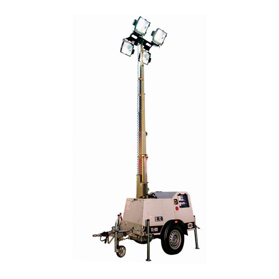
SMC Light & Power WARRANTY Warranty pertaining to your Telelight is explained in the Company’s separate booklet entitled Registration & Warranty Information. This booklet should be read in conjunction with these operator’s guidance notes. IDENTIFICATION OF WARNINGS & DANGER Failure to follow the warning instructions could result in severe injury or death to the operator, a bystander or a person inspecting or repairing the machine. - Page 6 SMC Light & Power A central lifting eye and fork pockets are incorporated for ease of loading on & off transport. The rotating mast has 9 sections that extend by hydraulic cylinder and via wire ropes to a height of 9.0 metres. The mast is fitted with four Metal Halide Lamps. Two external power sockets are provided.
-
Page 7: Safety Instructions
SMC Light & Power WARNING It is the responsibility of the operator to fully read the handbook & understand it before operating the machine. WARNING Voltage used in this equipment can endanger life. Before attempting WARNING replacement of components or maintenance operations, ensure that any power supply and the generator are switched off. - Page 8 SMC Light & Power Do not use the unit for lifting purposes or for anything other than that for which it is designed. 2.6 INSTRUCTION & SAFTEY LABELS ON MACHINE The drawings are provided by way of example. The operating instruction, warning & safety labels form an integral part of the Telelight.
- Page 9 SMC Light & Power Figure 2 Side Elevation Figure 3 Rear Elevation + Radiator...
- Page 10 SMC Light & Power LA15647 Figure 4 Upper Elevation DIAGRAMS/ LABEL EXPLANATIONS Danger Symbols LA15461 Danger of entanglement and cutting. Presence of rotating parts, pulleys, belts and fan. LA16533 Danger of burns: Hot surfaces. LA15459 Danger of electric discharge: consult the manual. Danger of possible corrosive acid leaks.
- Page 11 SMC Light & Power LA 01945 Danger of burns: Possibility of pressurised hot water expulsion. LA15447 The fuels are highly flammable and can be explosive. Fill in well ventilated area with engine off. Do not smoke or create sparks while filling. Immediately clean off any fuel leaks.
- Page 12 SMC Light & Power General Labels LA16313 LA16351 LA15604 LA15584 Lamp Deployment Transport Mode Deployed Mode 1 Deployed Mode 2 LA15587 LA16350 (optional) LA15587 LA15933...
-
Page 13: Controls
SMC Light & Power LA15649 LA15602 Operation & Maintenance Manual Located behind rear access door LA16996 LA16996 CONTROLS Control Module... - Page 14 SMC Light & Power Control Module Button and LED Function This button switches on the engine control module and starts the engine. This button stops the engine and resets the module. This button tilts the lamps upwards (optional equipment) This button tilts the lamps downwards (optional equipment) This button raises mast This button lowers mast Permanent LED illumination means engine protection working...
-
Page 15: General
SMC Light & Power GENERAL USING THE OPERATION & MAINTENANCE MANUAL The scope of this document is to support the operator in safely deploying and maintaining the Telelight. This manual is organised in sections with the following information: Section 1 Warranty Information. - Page 16 SMC Light & Power SMC LIGHT & POWER A DIVISION OF ARC-GEN LTD MACHINE TYPE TL-90 SERIAL No. SGNT90003 7. 7 kW @ 1500rpm ENGINE POWER 1050 YEAR OF MANUFACTURE SMC Light & Power 1 - 1050 KG A DIVISION OF ARC-GEN LTD Gosberton, Lincs, PE11 4HG Tel: 44 (0) 1775 840020 Fax: 44 (0) 1775 843063 Website: www.smclightandpower.com...
-
Page 17: Ec Declaration Of Conformity
SMC Light & Power EC DECLARATION OF CONFORMITY 2. EC CONFORMITY CERTIFICATE No. 1. MANUFACTURER 1 SMC Light & Power A division of Arc-Gen Ltd. 2 SMC/EC/2248 Belchmire Lane, Gosberton, Lincolnshire PE11 4HG United Kingdom 3. CERTIFICATE HOLDER 4. ISSUING DIRECTIVE APPLICABLE 2006/42/EC 2000/14/EC and 2005/88/EC 2004/108/EC... -
Page 18: Tl-90 Technical Information
SMC Light & Power TL-90 TECHNICAL INFORMATION ENGINE Model Kubota D905-BG Type Diesel Water Cooled Cylinders Bore mm Stroke mm 73.6 Displacement cu.cm. Power. kWm 1500 Oil Sump Capacity. Litres Engine Stop System 12v Solenoid. Energised To Run Fuel Pump 12v Electric Fuel Tank Capacity. -
Page 19: Operation
SMC Light & Power OPERATION INSPECTION & PRELIMINARY OPERATION 4.1.1 Prior to each operation of the Telelight, including raising or lowering the mast, a thorough inspection should be made. Included in this inspection must be: a) Wire ropes and pulleys. Check rope for fraying, kinks and stretching. Replace if not good working order. -
Page 20: Manoeuvring
SMC Light & Power MANOEUVRING 4.2.1 Use sufficient persons and equipment to control the lighting tower when manoeuvring. Never manoeuvre with the mast raised. Prior to raising mast check for overhead obstructions and in particularly overhead electric power lines. Please consult HSE Guidance Note GS 6, Avoidance of danger from overhead electric power lines. -
Page 21: Starting The Engine
SMC Light & Power STARTING THE ENGINE 4.6.1 Ensure MCB’s are switched off when starting and stopping the engine, failure to do so could damage the alternator. 4.6.2 Check fuel, oil and coolant, if appropriate, as per the instructions in the engine manufacturer’s handbook. -
Page 22: Operating The Lights
SMC Light & Power OPERATING THE LIGHTS 4.8.1 Ensure procedures described in 4.4 have been carried out. 4.8.2 Check, wherever practical, that electrical connections are in good condition. 4.8.3 Carry out procedures described in 4.6.1 4.8.4 Switch on lamp MCB’s, one at a time. WARNING OUTLET POWER SOCKETS. -
Page 23: Preparing For Removal From Site
SMC Light & Power CAUTION 4.11 PREPARING FOR REMOVAL FROM SITE. 4.11.1 Following lowering of the mast as described in 4.10 above. 4.11.2 Raise jacklegs and ensure they are well secured in their clamps. Retract outriggers and ensure they are well secured. 4.11.3 Adjust lamp fittings to transport position, see instruction labels on unit, lock off all retaining fasteners. -
Page 24: Lifting The Telelight
SMC Light & Power WARNING LIFTING THE TELELIGHT 5.2.1 Employ suitable slings and equipment. Follow best practices and obey local regulations. 5.2.2 Ensure mast, lamps, stabiliser legs and control panel covers are all locked in their transport mode as 4.11. Note: when utilising the central lifting eye rotate lamps through 90 degrees to enable safe access to the lift point. -
Page 25: Storage
SMC Light & Power STORAGE The storage operation is very important in order to preserve the efficiency of the Telelight. There are some operations suggested only for long-term storage (over 3 months) and others for medium term storage (up to 3 months). Others are to be carried out each time that the Telelight is out of regular use. -
Page 26: Safety Information
SMC Light & Power Note: for terminology refer to descriptions in parts manual. NOTE! In case of emergency it is always possible to shut down the Telelight by pushing the Emergency Stop push button located on the control panel. WARNING SAFETY INFORMATION In addition to the general safety information mentioned in section 2, it is important to pay attention during maintenance operation to the instructions listed below:... -
Page 27: Routine Maintenance
SMC Light & Power ROUTINE MAINTENANCE This section provides general instructions for the Telelight maintenance and a summary of the principal maintenance operations of the parts. Complete maintenance instructions for the main parts (engine & alternator) are detailed in the relevant specific manuals supplied with the Telelight. OPERATION DAILY 125Hr... -
Page 28: Diesel Generator Maintenance
SMC Light & Power DIESEL GENERATOR MAINTENANCE OPERATION The engine oil level should be checked daily. The level must be between the marks ‘Min’ and ‘Max’ marked on the dipstick. Refill if necessary without exceeding the ‘Max’ position. The oil must be replaced in accordance with the engine manufacturers recommendation. -
Page 29: Mast Disassembly & Reassembly
SMC Light & Power MAST DISASSEMBLY & REASSEMBLY 7.1. DISASSEMBLY 7.1.1 Disconnect the coiled cable from the terminal box on top of the light bar and remove the cable gland. Remove the upper & lower cable guides. Pull the coiled cable down through the square hole in the outer mast section ring. 7.1.2 Remove the hydraulic hose from the hose fitting at the base of the hydraulic cylinder taking care to contain any spillage of hydraulic oil. -
Page 30: Reassembly - Wearpads
SMC Light & Power pulley mounting plates at the top of section 2 and secure the rope to the anchor point on mast section 1 using cable retaining pin (PM15486) and 2 off 16mm circlips. Place a large pulley assembly (TM15490) and pin (TM15819) into the pulley mounting plates at the top of Mast Section 2 and slide this section in until the wire rope is wrapped securely around the pulley. - Page 31 SMC Light & Power 1-off yellow corner pad (TM15165), 1-off white corner pad (TM15164), 4-off M6 x 25 setscrews, 4-off M6 nyloc nuts, 8-off M6 flat washers, 1-off pulley assembly (TM15491), 1-off pulley pin (TM15818) at the top of section 5. 1-off pin (PM15264), 2-off 10mm circlips at the top of section 4.
-
Page 32: 8. Tl-90 Troubleshooting
SMC Light & Power 8. TL-90 TROUBLESHOOTING Fault Probable Cause Emergency Stop Switch Engaged Thermal Fuses Activated (LED Illuminated on Control Panel) Flat Or Low Battery Voltage Machine Will Not Switch On Battery / Starter Cable Disconnected, Loose or Broken Broken or Loose Positive Feed Cable Broken or Loose Negative Feed Cable Faulty Control Module... - Page 33 SMC Light & Power TL-90 TROUBLESHOOTING MAINS VOLTAGE ALTERNATOR FAULTS Fault Probable Cause Low Engine Speed Faulty Capacitor No Output From Faulty Windings Alternator Loose or Broken Output Cables Faulty RCD High Engine Speed High No-Load Voltage Output From Alternator Faulty or Incorrect Capacitor Low Engine Speed Faulty Rotary Diodes...
- Page 34 SMC Light & Power TL-90 TROUBLESHOOTING MAST OPERATING FAULTS Probable Cause Fault Handbrake Not Applied Low Battery Voltage (Engine Not Running) Thermal Fuses Activated (LED Illuminated on Control Panel) No or Low Hydraulic Oil in Reservoir Hydraulic Hose Connection Leaking Mast Will Not Raise Faulty or Broken Handbrake Switch Mast Raise Solenoid Feed Cable Loose or Broken...
- Page 35 SMC Light & Power TL-90 TROUBLESHOOTING LAMP OPERATING FAULTS Probable Cause Fault RCD not Switched On Lamps Are Hot Fused or Loose Lamp Faulty MCB Lamps Will Not Ignite Loose or Broken Ballast Cable / Connections Loose or Broken Mast Cable / Connections Faulty Ballast Faulty Igniters No Output From Alternator...
Need help?
Do you have a question about the SMC TELELIGHT TL-90 and is the answer not in the manual?
Questions and answers