
Summary of Contents for Devantech dS2832
- Page 1 User Manual v4.10 dS2832 dS2832 User Manual Version 4.10 Copyright © 2016-2022, Devantech Ltd. www.robot-electronics.co.uk All rights reserved.
-
Page 2: Table Of Contents
User Manual v4.10 Table of Contents Documentation history.........................3 A quick look..........................4 Introduction..........................5 Getting started...........................6 Locating the IP Address....................7 Configuring the dS2832.......................9 Status page......................10 Network page......................11 Webpage security......................12 TCP/IP page......................14 Configuring relays.....................16 Relay automation.....................17 Input/Output configuration..................20 Connecting I/O to Relays....................21 dSx Configuration.....................22... -
Page 3: Documentation History
Analogue channels......................64 Serial port connections....................66 dS2832 dimensions........................67 Notes............................68 Documentation history V4.06 First release of the dS2832 manual. V4.07 Added new features: Ping Used to ping other machines to check if responding. Sequencer Added a 120 step, 12 output sequencer v4.08... -
Page 4: A Quick Look
Schedules – Able to schedule events based on time of day/week Counter/Timers – Count or time events. 10 counts/second Max. Also available when optionally programming in dScript is a TTL level serial port and an RS485 serial port. Copyright © 2016-2022, Devantech Ltd. www.robot-electronics.co.uk All rights reserved. -
Page 5: Introduction
Each relay has both normally open (NO) and normally closed (NC) as well as the common available on three terminals. In addition to the relays, the dS2832 has 8 flexible I/O channels which may be individually configured to be: 1. -
Page 6: Getting Started
Just go to the chapter on installing the firmware and follow the instructions there). If you are using a Win7/8/10 PC, open your browser and into the address bar (not the search bar) type: http://dS2832/index.htm You should now see the application webpage and you can control relays and I/O's. Copyright ©... -
Page 7: Locating The Ip Address
IP address. Alternatively, if you have a DHCP server on your network (your router is normally the DHCP server) then the dS2832 will get its IP address from that. Log on to your router and navigate to the LAN client list. - Page 8 LAN. DevantechModuleFinder.jar If you do not have a DHCP server the dS2832 will use a default IP address of 192.168.0.123 so make sure your PC is on the same subnet of 255.255.255.0 and its IP address is 192.168.0.xxx...
-
Page 9: Configuring The Ds2832
User Manual v4.10 Configuring the dS2832 There are a set of configuration pages to get the dS2832 operating as you want it. These pages are all _configx.htm, (that's a leading underscore character). _config.htm _config2.htm Anything that starts with _config is considered a special name for configuration pages and can only be seen if you have the the USB cable plugged in and connected to your PC. -
Page 10: Status Page
The system reboot button should be used with caution. If the module is at a remote site and you change the IP address, you may not be able to reach it again. Copyright © 2016-2022, Devantech Ltd. www.robot-electronics.co.uk All rights reserved. -
Page 11: Network Page
Red led comes on after you press the reset button, its because you pressed it for too long (and entered bootloader mode). Just have another go with the reset button for a bit less time. Copyright © 2016-2022, Devantech Ltd. www.robot-electronics.co.uk All rights reserved. -
Page 12: Webpage Security
Accessing a special webpage, _pw.htm, will install the password on your browser. To do this make sure the Enable _pw.htm box is checked. When the “Update Pending” light goes out, re-boot the module and go to yourIP/_pw.htm You will see something like this: Copyright © 2016-2022, Devantech Ltd. www.robot-electronics.co.uk All rights reserved. - Page 13 The default port used by html webpages is 80. You can change this if required. If you do so then you will need to include the port number in the address. If you change the port to 2345 then the webpage will be at: YourIP:2345/index.htm For example: 192.168.0.123:2345/index.htm Copyright © 2016-2022, Devantech Ltd. www.robot-electronics.co.uk All rights reserved.
-
Page 14: Tcp/Ip Page
Phone App confiqures the module for control with our “IO network 2” app, available on iTunes/Play store. Password is an 8 character password used only with the App. Change this to a password of your choice and use the same password on your phone. Copyright © 2016-2022, Devantech Ltd. www.robot-electronics.co.uk All rights reserved. - Page 15 When selecting the Modbus commands, an additional set of configuration boxes are available. These allow you to select the UID, normally you will leave this at the default of 1. The dS2832 will respond to commands on this UID. If you send any other UID it will be treated as the ad- dress of a Modbus module connected to the RS485 port.
-
Page 16: Configuring Relays
Use the Relay No. box to select the relay to configure. There are 32 relays available. Unlike other dS modules the dS2832 does not have virtual relays. All relays 1-32 are the physical re- lays, however I/O lines may still be be linked to relays to provide additional physical outputs, see next section for details. -
Page 17: Relay Automation
This selects the relay you wish to configure. On other dS modules this is to connect virtual re- lays to the I/O ports, however as the dS2832 has all 32 relay slots occupied there are no vir- tual relays. Relays can still connected to an I/O port, but on the dS2832 it provides limited ad- ditional function. - Page 18 The exclamation mark is read as “Not R1”. Now relay 1 will always be the opposite of relay 2. Try it. Boolean equations may be used for controlling relays and other objects such as email. See the “Boolean equation” section later in this manual for full documentation. Copyright © 2016-2022, Devantech Ltd. www.robot-electronics.co.uk All rights reserved.
- Page 19 When checked, the relay is restored to the previous state it had when power was lost. If the relay was on when power was lost or the module was turned off, then the relay will be turned on when the module is powered up again. Copyright © 2016-2022, Devantech Ltd. www.robot-electronics.co.uk All rights reserved.
-
Page 20: Input/Output Configuration
The analogue modes convert the input volts to a digital number in the range 0-4095 (12-bit conversion). The input voltage range is selectable for 4.096v (Analog Ref4) and 5v (Analog Ref5). Copyright © 2016-2022, Devantech Ltd. www.robot-electronics.co.uk All rights reserved. -
Page 21: Connecting I/O To Relays
Any relay may be selected for an I/O. When you have configured the I/O, wait for the “Update Pending” light to go out and press the reset button, as new I/O modes are set on power-up. Copyright © 2016-2022, Devantech Ltd. www.robot-electronics.co.uk All rights reserved. -
Page 22: Dsx Configuration
I/O modules that are connected to the RS485 bus (serial port 3). Up to 16 dSx modules may be added, controlled by the dS2832 as if they are local I/O. The outputs are mapped to 2 of the 32 relays – real or virtual and the inputs can be accessed in the range 100-163. -
Page 23: Dsx Mapping Table
(real or virtual). Mapping a module to position 5 means that relays 1 and 2 on the dSx module will be controlled by virtual relays 5 and 6 on the dS2832. The mapping can be changed by selecting a new mapping with the drop-down box. - Page 24 Position 1 is not shown because all dScript modules have relays there and inputs 100 & 101 are not available so you will probably not use that position, but you can if you need to. Copyright © 2016-2022, Devantech Ltd. www.robot-electronics.co.uk All rights reserved.
-
Page 25: Dsx Example
As part of your system documentation, record the mapping number against mod- ule task so you can quickly restore the system should you need to. Copyright © 2016-2022, Devantech Ltd. www.robot-electronics.co.uk All rights reserved. - Page 26 This means the relay will turn on when the input is below 509 (508 or less), but will not turn off again until the input is above 512 (513 or more). The greater the difference between the two numbers, the greater the hysteresis. Copyright © 2016-2022, Devantech Ltd. www.robot-electronics.co.uk All rights reserved.
-
Page 27: Pinging Remote Machines
If set to 5 it will take 5 consecutive failed responses to trigger a failure. If a response is received, say on the 3 try, the attempt counter is reset to 5. Copyright © 2016-2022, Devantech Ltd. www.robot-electronics.co.uk All rights reserved. -
Page 28: Delay
To do this enter 2000 in the pulse/follow box and P1<1 in the Set Relay box. If you are going to reboot by removing power, you might want a longer pulse, say 30000mS or 30 seconds. You might also send a notification email: Copyright © 2016-2022, Devantech Ltd. www.robot-electronics.co.uk All rights reserved. -
Page 29: Email Notifications
Boolean equations are used for controlling relays as well as triggering email notifications. See the “Boolean equation” section later in this manual for full documentation. Note - Email notifications are limited to 100/hour. Copyright © 2016-2022, Devantech Ltd. www.robot-electronics.co.uk All rights reserved. -
Page 30: Peer To Peer
3 – Reset Relay, the relay will be reset by this event. You will need another P2P event to set it. 4 – Toggle Relay, this will toggle the relay each time the event is triggered. 20+ - Pulse relay, Pulse times are in mS. (1000mS=1Second). 5-19 will have no action. Copyright © 2016-2022, Devantech Ltd. www.robot-electronics.co.uk All rights reserved. -
Page 31: Sequencer
The K1 – K12 outputs may be used in boolean equations to control relays, send emails, etc. Placing K1 in a relays Pulse/Follow box will make the relay follow the K1 output, in this case pulsing the relay on and off every two seconds. Copyright © 2016-2022, Devantech Ltd. www.robot-electronics.co.uk All rights reserved. -
Page 32: Sequencer Commands
Tests R1 (Relay 1) and jumps to line 12 if active (on). D1, 20 Tests D1 (Digital Input 1) and jumps to line 20 if active. S1, 30 Tests S1 (Schedule 1) and jumps to line 30 if active. Copyright © 2016-2022, Devantech Ltd. www.robot-electronics.co.uk All rights reserved. -
Page 33: K Outputs
Here is a sequence for a 2-way traffic control of the type you normally see at road works. Copyright © 2016-2022, Devantech Ltd. www.robot-electronics.co.uk All rights reserved. - Page 34 To watch it happen, set relays 21, 25 & 29 to K1, K2 & K3 and set relays 24, 28 & 32 to K4, k5 & K6. Then look at the application page. Copyright © 2016-2022, Devantech Ltd. www.robot-electronics.co.uk All rights reserved.
- Page 35 Reset Relay box. Also enter K8 and K9 into relay 23 and relay 27 pulse/follow boxes. While we are in the relay section, lets rename the relays to better reflect their functionality. Copyright © 2016-2022, Devantech Ltd. www.robot-electronics.co.uk All rights reserved.
- Page 36 Also remove all ticks from K1 – K12 on these lines. The Call instruction will ignore them anyway, but it’s good to keep things clear. Enter the following on page 2. Copyright © 2016-2022, Devantech Ltd. www.robot-electronics.co.uk All rights reserved.
- Page 37 Line 17 returns the pedestrian signal to Red and waits a further 5 seconds for pedestrians to complete the crossing. Line 18 returns to the main sequence on page 1. Give it a try! Copyright © 2016-2022, Devantech Ltd. www.robot-electronics.co.uk All rights reserved.
-
Page 38: Schedules
The current time originates from an internet time server. It is read only and cannot be changed. Therefore you must have an internet connection for the scheduler to operate cor- rectly. Copyright © 2016-2022, Devantech Ltd. www.robot-electronics.co.uk All rights reserved. - Page 39 As well as controlling a relay directly, schedules may also be used in the boolean equation fields of other controls. A relay could be controlled by placing S1 (for schedule 1) in its auto- mation field. Copyright © 2016-2022, Devantech Ltd. www.robot-electronics.co.uk All rights reserved.
-
Page 40: Counter/Timers
This is the event that will cause the current counter value to be stored in the capture register. The capture register is displayed on the application page, and may also be read using the TCP/IP commands. Copyright © 2016-2022, Devantech Ltd. www.robot-electronics.co.uk All rights reserved. - Page 41 When it gets reset to zero each hour, so does counter 2. As the capture input is blank the reset event also captures the count value. This may be read any time in the next hour. Copyright © 2016-2022, Devantech Ltd. www.robot-electronics.co.uk All rights reserved.
- Page 42 1 second past midnight each day. The second start/stop time is disabled as both times are identical. Go back to counter1 and add “|S1” to the reset input. Now our time base timer will reset every hour or when schedule1 triggers it. Copyright © 2016-2022, Devantech Ltd. www.robot-electronics.co.uk All rights reserved.
-
Page 43: The Application Page
Red indicates an active output from the module. The I/O's are clickable just like the relay buttons to turn them on and off. The first 4 of the 8 counters are shown, together with their capture registers. Copyright © 2016-2022, Devantech Ltd. www.robot-electronics.co.uk All rights reserved. -
Page 44: Application Page Security
To summarize, set a password, load it onto your browser, disable _pw.htm and un-plug the USB cable. Now you, and only you, can access and control your module. Copyright © 2016-2022, Devantech Ltd. www.robot-electronics.co.uk All rights reserved. -
Page 45: Accessing Your Webpage From The Internet
Unfortunately there are so many routers out there we cannot give details on all of them. You should consult your routers manual or search Google for details on your specific router. Copyright © 2016-2022, Devantech Ltd. www.robot-electronics.co.uk All rights reserved. -
Page 46: Boolean Equations
The answer is that boolean expressions are evaluated left to right. So D2 is ORed with D3 and the result ANDed with D4. You can change the order of precedence by using parenthesis (). D2|(D3&D4) will now AND D3 with D4 and the result is Ored with D2. Copyright © 2016-2022, Devantech Ltd. www.robot-electronics.co.uk All rights reserved. - Page 47 A1 climbs above 1234. So the relay becomes active when A1 is below 1000 and inactive above 1234. We have hysteresis! Copyright © 2016-2022, Devantech Ltd. www.robot-electronics.co.uk All rights reserved.
-
Page 48: Tcp/Ip Command Sets
ASCII commands are all two character commands and are not case sensitive. Type ST followed by the return key. This is the STatus command. You will see: Copyright © 2016-2022, Devantech Ltd. www.robot-electronics.co.uk All rights reserved. - Page 49 GC 1 Get Counter 1 – responds with count, capture values. Note – on the dS2832, GI and GA are identical, getting the digital state or analogue value de- pending on the port configuration in the I/O Types tab. Typical PuTTY session.
-
Page 50: Binary Command Set
Update all Relays 0x30 (decimal 48) Get Status (1 byte command, returning 8 bytes) This command returns 8 bytes of status data Module ID This will be 42 (0x2A) for the dS2832 System Firmware Major 2 for example System Firmware Minor... - Page 51 8 inputs. Bit 7 is input 8 through to bit 0 which is input 1. If the bit is high the input is active. Byte 2 Bit No. 7 Input Copyright © 2016-2022, Devantech Ltd. www.robot-electronics.co.uk All rights reserved.
- Page 52 Clears only those relays with a corresponding high in the bit pattern returning an ACK/NACK byte. ACK=0, NACK=non-zero. Same bit order as command 0x37 above. Relays with a corresponding low (0) are NOT affected and remain on/off as previously set. Copyright © 2016-2022, Devantech Ltd. www.robot-electronics.co.uk All rights reserved.
-
Page 53: Aes Binary Command Set
0x38 – Set only relays with corresponding bit set to On 0x39 – Clear only relays with corresponding bit set to Off A Nounce is only ever used once, you must always used the most recently issued Nounce. Copyright © 2016-2022, Devantech Ltd. www.robot-electronics.co.uk All rights reserved. - Page 54 If the Nounce you send with the command does not match the last one sent to you, then the Relay (or Output) will not be changed. No other commands either require or provide a Nounce. Copyright © 2016-2022, Devantech Ltd. www.robot-electronics.co.uk All rights reserved.
-
Page 55: Modbus Commands
Capture7 high word Register 22 Counter7 low word Register 38 Capture7 low word Register 23 Counter8 high word Register 38 Capture8 high word Register 24 Counter8 low word Register 40 Capture8 low word Copyright © 2016-2022, Devantech Ltd. www.robot-electronics.co.uk All rights reserved. -
Page 56: Function 05 (0X05) Write Single Coil
This could be an MBH88 for example. The return frame is then converted back to Modbus/TCP/IP format and returned to you. Make sure you set the Parity and Baud Rate in the TCP/IP config screen to match your Modbus RTU modules. Copyright © 2016-2022, Devantech Ltd. www.robot-electronics.co.uk All rights reserved. -
Page 57: Loading The Application Firmware
In this order: 1. Start from this position: a. dScript Editor closed down. b. dS2832 not connected or powered. 2. Power-up the dS2832. 3. Hold down the reset button for a couple of seconds until the red LED comes on. This in- dicates the module is in boot-loader mode. - Page 58 7. Load the project: File Open project → \dScriptPublish-4-10\Examples\app-dS2832-v4-10\app-dS2832-v4-10.dsj 8. Click the build button (white triangle on green button). This will update the system firmware and load the application. 9. When done, the new version will be displayed: Copyright ©...
-
Page 59: Erasing Old Configuration Settings
Load up the app-dS2832-v4-10 application in the editor, but before you upload it to the dS2832 you need to make a small change. Locate the thread "main" (click the word in the right panel is quickest). Just below this is a commented out line "init()". -
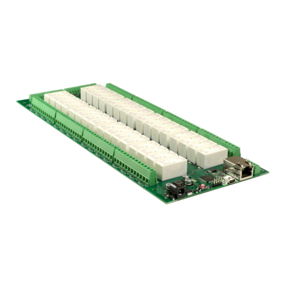
Page 60: Ds2832 Hardware
User Manual v4.10 dS2832 hardware Copyright © 2016-2022, Devantech Ltd. www.robot-electronics.co.uk All rights reserved. -
Page 61: Led Indication
Power supply The dS2832 requires a 12v DC supply capable of supplying a minimum of 2A. This is most eas- ily provided by a low cost mains adapter. A suitable universal adapter is available on our web- site and may be ordered along with the modules. -
Page 62: Power Relays
The relay coil is powered by the 12vdc incom- ing supply on user command. Coil Relay in passive state Coil Relay in powered state A full datasheet for the relays used on the dS2832 is here: HF115FD datasheet Copyright © 2016-2022, Devantech Ltd. www.robot-electronics.co.uk... -
Page 63: Analogue/Digital Flexible I/O's
User Manual v4.10 Analogue/Digital flexible I/O's The dS2832 has eight flexible I/O ports, numbered 1-8, which can be your selection of: 1. Digital open collector output. 2. Digital open collector output with passive pullup to 12v 3. Digital input (0-12v, 2.5v threshold). -
Page 64: Temperatue Sensor
This will give you volts*10. So 119 = 11.9v, 120 is 12.0v Analogue channels Temperature Voltage Channels 1–8 are Flexport channels, 12-bit resolution using 5v from regulator as reference. Channels 100,101 are 10-bit resolution, using CPU 3.3v supply as reference. Copyright © 2016-2022, Devantech Ltd. www.robot-electronics.co.uk All rights reserved. - Page 65 It is set by writing to the port. D1 is the ports input. It supplies the 12bit ADC in analogue modes and is read as 0 or 1 in digital modes. Copyright © 2016-2022, Devantech Ltd. www.robot-electronics.co.uk All rights reserved.
-
Page 66: Serial Port Connections
The two pin link near to the RS485 terminal block should be shorted to use the on-board 120 ohm terminating resistor. Notes. 1. Serial port 2 is not available on the dS2832. 2. Serial ports are available when programming in dScript Copyright © 2016-2022, Devantech Ltd. -
Page 67: Ds2832 Dimensions
User Manual v4.10 dS2832 dimensions Copyright © 2016-2022, Devantech Ltd. www.robot-electronics.co.uk All rights reserved. -
Page 68: Notes
User Manual v4.10 Notes Copyright © 2016-2022, Devantech Ltd. www.robot-electronics.co.uk All rights reserved.
Need help?
Do you have a question about the dS2832 and is the answer not in the manual?
Questions and answers