Advertisement
Quick Links
Electrical Equipment
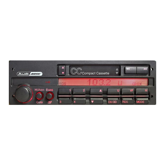
Stereo radio 'Gamma CC Bose' with CD changer, component layout
Front antenna amplifier, checking
Test conditions
●
Battery OK
●
Power window circuit breaker -S43- (in auxiliary relay panel I) OK
●
5 amp fuse on radio OK
●
Use multimeter (Fluke 83 or equivalent) and connector test kit VW 1594 for all electrical tests
Always use appropriate wiring diagram when troubleshooting
‒ Remove right side A-pillar trim.
‒ Leave front antenna amplifier mounted (Ground (GND) connection).
Note:
FM signals are received by both front and rear window antennas.
‒ Refer to illustration 90-912 => page
Checking front
antenna amplifier
power supply
‒ Disconnect
power supply
(B+) wire 4
connector
‒ Set multimeter
to milliamp
range
‒ Connect
multimeter
between two
halves of power
supply (B+) wire
4 connector
If specified readings are obtained:
‒ Remove radio.
‒ Remove antenna cable from front antenna amplifier.
‒ Set multimeter (Fluke 83 or equivalent) to measuring resistance ( Ω ).
‒ Connect multimeter between radio end and amplifier end of front antenna cable.
vw-wi://rl/A.en-US.4A-EA-EA.wi::27980645.xml?xsl=2
91-29
for component callout references.
● •
Test conditions
‒ Test steps
● •
Set multimeter
(Fluke 83 or equivalent)
to volt range
‒ Connect multimeter
between power supply
connector and Ground
(GND)
‒ Switch radio ON
‒ Switch radio ON
Specified
Repairing malfunction
reading
‒ Check wiring for open
Approx.
circuit according to
12 V
wiring diagram, repair
as necessary
‒ Check wiring for open
circuit according to
Approx.
wiring diagram, repair
20 - 50
as necessary or
mA
‒ Replace front antenna
amplifier
Page 1 of 2
4/1/2009
Advertisement

Subscribe to Our Youtube Channel
Summary of Contents for Audi Gamma CC Bose
- Page 1 Electrical Equipment Page 1 of 2 Stereo radio 'Gamma CC Bose' with CD changer, component layout Front antenna amplifier, checking Test conditions ● Battery OK ● Power window circuit breaker -S43- (in auxiliary relay panel I) OK ● 5 amp fuse on radio OK ●...
- Page 2 Electrical Equipment Page 2 of 2 ● Center core: must be 0 ohms ( Ω ) (continuity) ● Braided shield: must be 0 ohms ( Ω ) (continuity) If NOT: ‒ Replace antenna cable. Note: Foreign substances such as paint, primer and windshield adhesive may conduct electricity and cause an unwanted connection between antenna and car body (GND) resulting in poor radio reception.
Need help?
Do you have a question about the Gamma CC Bose and is the answer not in the manual?
Questions and answers