
Summary of Contents for Systema EOLO LX
- Page 1 EOLO LX HEAT EXCHANGER GAS UNIT Instruction manual installation, use and maintenance ENGLISH Rev. 00ITIT20210827...
- Page 2 Before installation, make sure that the local distribution conditions, the nature of the gas and the pressure correspond to the settings of the device. Systema Polska reserves a right to modify product content for the purposes of product improvement at sole discretion without preliminary notice.
-
Page 3: Table Of Contents
8.1.4 Pre-settings of gas valve VK4415V1002B after gas type change............................64 8.1.5 Replacement of the Venturi for gas valve VR415/ VR420 ..............................65 8.1.6 Pre-settings of gas valve VR415/VR420 after gas type change............................66 FAULTS AND REMEDIES ......................................67 Systema Polska Sp. z o.o. Lennox rev. 00ITIT20210827... - Page 4 OBJECT AND DURATION OF THE WARRANTY ..............................69 WARRANTY EXCLUSIONS ....................................... 69 OPERATION AND EFFECTIVENESS OF WARRANTY ............................69 RESPONSIBILITY ........................................69 SHUTDOWN AND DISPOSAL ......................................70 10.1 SHUTDOWN ..........................................70 10.2 DISPOSAL ........................................... 70 Systema Polska Sp. z o.o. Lennox rev. 00ITIT20210827...
-
Page 5: General Rules
It is mandatory to follow the instructions in this manual, particularly concerning safety rules. ■ In no case will Systema be responsible for any direct or indirect damage to humans, animals, or property, resulting from ■ user’s failure to follow the instructions given in this manual. -
Page 6: Exploitation
Note Insert the EOLO LX series gas units in a system with an adequate air flow rate (see the nomi- nal air flow rate indicated in tables 2.1 and 2.2) Systema Polska Sp. -
Page 7: Terms And Definitions
C4 warm air heater is marketed as a C4 warm air heater only; Slave Card (SCP674V202MB) installed on the machine equipped with a port for connecting the device to a serial network. Tab. 1.1 Definition Systema Polska Sp. z o.o. Lennox rev. 00ITIT20210827... -
Page 8: Features
Genius M82 Control electronics (motherboard) SCP674V130B1 Automatic control electronics (slave board) SCP674V202MB Tab. 2.1 Tecnical data (1 of 2) (*) For gases G25 / G27 / G2.350 (**) Referred to methane G 20 Systema Polska Sp. z o.o. Lennox rev. 00ITIT20210827... - Page 9 G1G 170 Venturi 45900450N-030 VMU185 VMU300 Flame controler Genius M82 Control electronics (motherboard) SCP674V130B1 Automatic control electronics (slave board) SCP674V202MB Tab. 2.1 Tecnical data (2 of 2) (*) Referred to methane G 20 Systema Polska Sp. z o.o. Lennox rev. 00ITIT20210827...
-
Page 10: Identification Plate And Information Labels
For type B applications, please forsee adequately ventilated spaces. XXXX Footwear by Helmet of Gloves of safety protection protection Fig. 2.3 Labels placed on the packaging for the obligation of individual protection devices Systema Polska Sp. z o.o. Lennox rev. 00ITIT20210827... - Page 11 XXXXXXXXXXXXXXX EOLOLXC 50 XXXX XXX XX XXXXXXX L20H110 12 Device adjusted for: SYSTEMA POLSKA Sp. z o.o. ul. Długa 5 98-220 Zduńska Wola/ POLSKA Device adjusted for: www.systemapolska.pl Read the installation instructions before ........ / ......... mbar Condensing gas unit 2020 installing and switching on the appliance.
-
Page 12: Overall Dimensins
EOLO EOLO EOLO EOLO EOLO EOLO Dim. LXC 50 LXD 70 LXE 90 LXE+ 110 LXF 130 LXG 170 LXH 230 1022 1518 1785 1785 1906 2212 2212 Tab. 2.4 Overall dimensions Systema Polska Sp. z o.o. Lennox rev. 00ITIT20210827... -
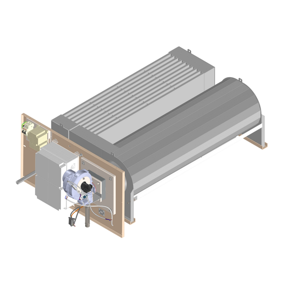
Page 13: Component Arrangement
Gas valve power cable Gas connection Gas blower wire Housing for 4 outlet airflow temperature probes Venturi Lo temperature kit 150 W with capillary thermostat 0 ÷ 40 ° C (optional) Tab. 2.5 Components Systema Polska Sp. z o.o. Lennox rev. 00ITIT20210827... -
Page 14: List Of Components
FEATURES LIST OF COMPONENTS Uwaga: -Ostre krawędzie stępić Fig. 2.6 Components Tab. 2.6 Uwaga: -Ostre krawędzie stępić Systema Polska Sp. z o.o. Lennox rev. 00ITIT20210827... - Page 15 Green flame signal lamp White lamp indicating power supply present Min air flow pressure switch (Pa) 4 pin adaper Insulation box with cover for electrical installation Safety thermostat (Tso) Reset button (Sr) SCP674V130B1 motherboard Systema Polska Sp. z o.o. Lennox rev. 00ITIT20210827...
-
Page 16: Burner
Electrode set 94CNEL0035 Solenoid valve wire supply 00CECO1109 Blower support Gas blower wire supply 70OKWI0003 Gas blower NRG118 94CNVE0019 Nut M6 10WSNA2021 Gas air-mixer 94CNIM0033 Transformer 00CNAC2008 Solenoid valve 94CEVA0010 Tab. 2.7 Systema Polska Sp. z o.o. Lennox rev. 00ITIT20210827... -
Page 17: Vip 2 Hw
Gas blower support Gas blower control cable 70OKWI0000 Gas blower 94CNVE0012 Solenoid valve wire supply 00CECO1109 Gas air-mixer 94CNM0033 Gas blower wire supply 70OKWI0007 Solenoid valve 94CEVA0010 Nut M6 10WSNA2041 Tab. 2.8 Systema Polska Sp. z o.o. Lennox rev. 00ITIT20210827... -
Page 18: Vip 3 Hw A/B
Hex screw M5x35 Gas blower 94CNVE0016 Solenoid valve wire supply 00CECO1106 94CNIM0023 Gas air-mixer Gas blower control cable 70OKWI0000 Solenoid valve 94CEVA0011 Gas blower wire supply 70OKWI0003 Gas connection 94ARSZ6009 Tab. 2.9 Systema Polska Sp. z o.o. Lennox rev. 00ITIT20210827... -
Page 19: Vip 4 Hw A
10WSNA2022 94CNIM0023 Gas air-mixer Solenoid valve wire supply 00CECO1106 Solenoid valve 94CEVA0011 Gas blower control cable 70OKWI0001 Gas connection 3/4 94ARSZ6009 Gas blower wire supply 70OKWI0004 3/4" anti-vibration joint 12ARPG6007 Tab. 2.10 Systema Polska Sp. z o.o. Lennox rev. 00ITIT20210827... -
Page 20: Vip 4 Hw B
Gas blower control cable 70OKWI0002 Gas air-mixer 94CNIM0015 Gas blower wire supply 70OKWI0005 94ARSZ6013 70OKWI0006 Flange connection 5/4" Solenoid valve wire supply Solenoid valve 94CEVA0005 Pressure swich 00CEPR1151 94ARSZ6014 Flange connection Tab. 2.11 Systema Polska Sp. z o.o. Lennox rev. 00ITIT20210827... -
Page 21: Vip 5 Hw A
Gas blower G1G 94CNVE0017 Gas blower wire supply Gas air-mixer 94CNIM0016 Gas blower contro cable 70OKWI0002 94ARSZ6014 Flange connection 5/4" Solenoid valve 94CEVA0005 Flange connection 5/4" 94ARSZ6013 Pressure swich 00CEPR1151 Tab. 2.12 Systema Polska Sp. z o.o. Lennox rev. 00ITIT20210827... -
Page 22: Wiring
(optional IN C-D-E-F BOX / standard in G-H BOX) P1 = Probe (PT 1000) exchanger limit temperature P3 = Inlet air flow temperature probe (NTC) P4.1 ... P4.4 = Probe (NTC) outlet air flow temperature Systema Polska Sp. z o.o. Lennox rev. 00ITIT20210827... - Page 23 It is mandatory to connect the appliance to earthing system. taking care to leave the ground wire slightly longer than the line wires so that in case of accidental pulling, the ground wire is the last one to be removed. Systema Polska Sp. z o.o. Lennox rev. 00ITIT20210827...
-
Page 24: Scp674V130B1 Card Connections (Main Board)
Minimum gas pressure switch connection (optional), otherwi- se the contacts are connected in bridge J7B-a2 Pg- (if present) J7B-b Contacts connected in bridge J7B-b Tab 3.1 Legend of SCP674V130B1 card connections (1 of 2) Systema Polska Sp. z o.o. Lennox rev. 00ITIT20210827... - Page 25 Consent to reset pending alarms, machine reset J1-RT-1/ J9B-R Sr; SL3-J1 IFS port for copying parameters or updating board firmware Connector for programming button —- Tab 3.1 Legend of SCP674V130B1 card connections (2 of 2) Systema Polska Sp. z o.o. Lennox rev. 00ITIT20210827...
-
Page 26: Scp674V202Mb Slave Card Connections
SCP674V122T2 (V+) Not connected SCP674V122T2 (L1) Connector for terminal connection to earth SCP674V122T2 (only for SERVICE) Not connected SCP674V122T2 (L2) Not connected SCP674V122T2 (V-) MODBus network connection Tab 3.2 Legenda connctions slave SCP674V202MB Systema Polska Sp. z o.o. Lennox rev. 00ITIT20210827... -
Page 27: Operation Of The Appliance
Screw and spring terminals for wires with a maximum section of 1.5 mm2 with the exception of J1A / J1B terminal blocks with terminal blocks for wires with a maximum section of 4 mm2 Systema Polska Sp. z o.o. Lennox rev. 00ITIT20210827... -
Page 28: Signals On The Display
10 seconds. Turned off Alarm EEPROM faulty alarm; try switching the instrument off and on again. Tab. 4.2 Signaling on display Systema Polska Sp. z o.o. Lennox rev. 00ITIT20210827... -
Page 29: Mainboard Operation
To restart the burner it is not sufficient to close the J7C contact. To cancel the serious alarm event, close J7C and reset the board, RT reset contact (connector J9B) using the Sr. Systema Polska Sp. z o.o. Lennox rev. 00ITIT20210827... -
Page 30: Burner Shutdown Due To Burner Fan Speed Exceeding
P key to scroll through the list of parameters; release the P key as soon as the desired parameter is displayed, the value of the parameter will now flash on the display for about 3 seconds; Systema Polska Sp. z o.o. Lennox rev. 00ITIT20210827... - Page 31 1 = RG 148 (VIP 2 HW), RG 175 (VIP 4 HW a), NRG 137 (VIP 3 HW a / b); 1...3 2 = NRG 118 (VIP 1 HW); 3 = G1G 170-AB53-01 (VIP 5 HW a). Release firmware (read only) Tab 4.3 Burner operating parameters Systema Polska Sp. z o.o. Lennox rev. 00ITIT20210827...
-
Page 32: Scp674V202Mb Slave Board Features
In this case the master uses the slave address 0, reserved for broadcast mode. ModBus communication takes place by sending data packets along the serial line, the packet complies with the following scheme: Tab. 4.5 Slave address Function Code Data Error Check Systema Polska Sp. z o.o. Lennox rev. 00ITIT20210827... -
Page 33: Serial Configuration Of Devices
In this case the network master must repeat the command. The exception code that is forwarded to the network master has the following format: code function Slave address exception code CRC (LSByte) CRC (MSByte) + 0x80 Tab. 4.6 Systema Polska Sp. z o.o. Lennox rev. 00ITIT20210827... -
Page 34: Command Description
The receiver re-calculates the CRC, then compares its result to the received CRC; if the two values are different the frame is ignored. The exception is not generated in case of a broadcast writing command. The transmitted data have always the following structure: Systema Polska Sp. z o.o. Lennox rev. 00ITIT20210827... -
Page 35: Scp674V202Mb Slave Card Programming
Please note Change the DIP switches only when the device is switched off. Fig. 4.2 Position DIP Switch in slave SCP674V202MB Systema Polska Sp. z o.o. Lennox rev. 00ITIT20210827... - Page 36 If the modbus port is in operating by the dip n ° 3 of SW2 the MODBus communication speed is set: SW2 (DIP 3) FUNCTION DESCRIPTION baud rate: 9600 bps. baud rate: 19200 bps. Tab 4.14 MODBus communication speed setting Systema Polska Sp. z o.o. Lennox rev. 00ITIT20210827...
-
Page 37: Dip Switch Configuration 3
MODBUS: SEt menu - set-point: modbus index base register 1 (base Reg. 1 column) in reading and writing. Reg. SIGN PARAMETER RANGE DEFAULT base 1 1025 Set-point. (steps of 0.1 signed) -50…150 °C 40° Tab 4.17 Systema Polska Sp. z o.o. Lennox rev. 00ITIT20210827... -
Page 38: Functions Menu: Fnc - Burner Reset
Probe value P4 MODBUS: Burner output status, keyboard lock status (read-only indices) Keyboard lock. MSByte: Bit 4: keyboard lock, 0=no; 1=YES; Burner status. LSByte: Bit 0: burner ouput, 0=off; 1=ON; Tab 4.19 Systema Polska Sp. z o.o. Lennox rev. 00ITIT20210827... -
Page 39: Menu Alarms: Alst
C = MANUFACTURER parameters. These parameters are typically set by the manufacturer, the default va- lues may be different from those recommended. Any modification may cause the connected equipment to malfunction. These parameters are only visible by entering the correct password. Systema Polska Sp. z o.o. Lennox rev. 00ITIT20210827... -
Page 40: Burner Operation Mode (Pwm)
The SCP674V202MB board, when the burner is lit, has a single operating mode: the PWM burner automati- cally modulates the power to keep the supply air flow temperature as equal as possible to the set set-point, SP (tab. 4.17, page 38). Systema Polska Sp. z o.o. Lennox rev. 00ITIT20210827... - Page 41 - If P3 = 10 ° C = Ln8 then the maximum PWM is equal to 50% of the maximum power; To disable the automatic correction of the maximum power, set Ln6 = Ln8 or LrA = 100. Systema Polska Sp. z o.o. Lennox rev. 00ITIT20210827...
-
Page 42: Gas Installation
Gas supply pressure adjustment: all appliances are tested and calibrated in the factory for the pressures for which they are designed (see burner plate data or table 5.1). WARNING Seal the gas valve adjustment body after calibration. Systema Polska Sp. z o.o. Lennox rev. 00ITIT20210827... - Page 43 G20=20 mbar G20=20 mbar Lithuania Turkey G31=37 mbar G30/G31=30 mbar 2H3P 2H3B/P G20=20 mbar G20= 25 mbar Lithuania Hungary G30/G31=30 mbar G30/G31=30 mbar 2H3B/P 2H3B/P Tab 5.1 Categories of gas and supply pressure Systema Polska Sp. z o.o. Lennox rev. 00ITIT20210827...
- Page 44 Gas pressure outlet located at the outlet of the appliance's gas valve Burner Ball valve with bleed Maximum gas pressure switch with manual reset (40 mbar) - optional Minimum gas pressure switch (20 mbar) - optional Tab 5.2 Gas components Systema Polska Sp. z o.o. Lennox rev. 00ITIT20210827...
-
Page 45: Installation
It is forbidden to stack pallets with gas heaters Pos. Description Heat exchanger gas unit Pallet Foil Foil Screw Tab. 6.1 Fig. 6.1 Packaging - models C, D, E - 3 units per 1 pallet Systema Polska Sp. z o.o. Lennox rev. 00ITIT20210827... -
Page 46: Packaging Dimensions
Fig. 6.3 transportation with a forklift Systema Polska Sp. z o.o. Lennox rev. 00ITIT20210827... -
Page 47: Exchanger Handling With Eyebolts
WARNING When operating an overhe- ad crane, the crane control should be supervised to prevent its use by unautho- Fig. 6.5 Unit handling rized persons during reloa- ding. Systema Polska Sp. z o.o. Lennox rev. 00ITIT20210827... -
Page 48: Condensate Drain
■ legislation requires the need to neutralize the condensates with a special system. Systema Polska Sp. z o.o. Lennox rev. 00ITIT20210827... -
Page 49: Condensate Stagnation In The Exchanger
EXHAUST DUCTS Important Do not install EOLO LX appliances in environments with mechanical extraction ventilation and local depression. The vacuum room can compromise the functionality of the EOLO LX appliances. - Page 50 Mount the horizontal elements of the flue gas duct with a slight slope (1 ° ÷ 3 °) towards the appliance to avoid the stagnation of the condensate inside the flue gas duct. Systema Polska Sp. z o.o. Lennox rev. 00ITIT20210827...
-
Page 51: Application In Air Conditioning Systems With Refrigerant Gas
WARNING The manufacturer of the air conditioning system must provide adequate information in the installation, use and maintenance manual for the use of refrigerating gases and risk assessment. Systema Polska Sp. z o.o. Lennox rev. 00ITIT20210827... -
Page 52: Conditions Installing The Appliance In An External Housing As Air Handling Unit
The device is fixed by attaching the mounting plate to the previously prepared flange. See the drawing be- low. Do not fix the feet of the exchanger to allow free expansion 8 x fixing holes in mounting plate Systema Polska Sp. z o.o. Lennox rev. 00ITIT20210827... -
Page 53: Testing And Start-Up Of The System
(if necessary, consult paragraph 8.1 on chan- ging fuel, page 61), check the gas type and pressure (see paragraph 5.1 on page 44) and turn on the gas; Systema Polska Sp. z o.o. Lennox rev. 00ITIT20210827... -
Page 54: Starting Up The Appliance
VIP 3 HW a VK4415V1002B EOLO LXF 130 VIP 4 HW a VK4415V1002B EOLO LXG 170 VIP 4 HW b VR415VE EOLO LXH 230 VIP 5 HW a VR420VE Tab. 7.1 Gas valve models Systema Polska Sp. z o.o. Lennox rev. 00ITIT20210827... -
Page 55: Gas Unit With Gas Valves Vr4205Ve5002B And Vk4415V1002B
Tab 7.1 Key for gas valves VR4205VE5002B and VK4415V1002B WARNING Seal the gas valve adjustment body after calibration and check that the pressure measure- ment screws (2), (3), (6) upstream and downstream of the solenoid valve have been screwed back. Systema Polska Sp. z o.o. Lennox rev. 00ITIT20210827... -
Page 56: Gas Unit With Gas Valve Vr415Ve5024
6) Put back the protection cap (4). WARNING Seal the gas valve adjustment body after calibration and check that the pressure measure- ment screw downstream of the solenoid valve has been screwed back. Fig 7.3 VR415VE5024 gas valve Systema Polska Sp. z o.o. Lennox rev. 00ITIT20210827... -
Page 57: Position Of Electrodes
Tab 7.1 Legend for gas valve VR415VE5024 POSITION OF ELECTRODES For correct ignition and flame detection, the electrodes must be positioned inside the head cone in the position in the drawing. 3-4 mm Fig. 7.4 Electrode position Systema Polska Sp. z o.o. Lennox rev. 00ITIT20210827... -
Page 58: Maintenance
- check the gas pressure upstream and downstream of the solenoid valve, adjust the maximum and mini- mum flow if necessary; - check the tightness of the gas system; Systema Polska Sp. z o.o. Lennox rev. 00ITIT20210827... - Page 59 Electrical system, conductors, terminals, etc. Various Combustion head fixing nuts PT1000 probe (P1) connected to connector J2 Blower fixing nuts Combustion chamber Blower plate fixing nuts Exchanger Combustion head support fixing nuts Combustion head support Systema Polska Sp. z o.o. Lennox rev. 00ITIT20210827...
-
Page 60: Fuel Change
10,9 10,7 NOX (O =0%) Important Put the appliance back into operation once the fuel change operations have been completed. WARNING Seal the regulating points of the gas valve after any calibration. Systema Polska Sp. z o.o. Lennox rev. 00ITIT20210827... -
Page 61: Replacement Of The Venturi For Gas Valve Vk4205Ve5002B
8. Screw on the hose coupling (2). 9. Restore the electrical connection (3). 10. Check the gas tightness on the joints before putting the appliance into service. 11. Open the main gas valve. Systema Polska Sp. z o.o. Lennox rev. 00ITIT20210827... -
Page 62: Pre-Settings Of Gas Valve Vk4205Ve5002B After Gas Type Change
20 mbar 45.900.451 056 full open next close 5 full open full open - turn left 37 mbar 45.900.451 040 next next 10,3 10,3 close 5 close 6,5 - turn right Systema Polska Sp. z o.o. Lennox rev. 00ITIT20210827... -
Page 63: Replacement Of The Venturi For Gas Valve Vk4415V1002B
10. Paste the appropriate sticker ("Regulated for ...") indicating the new type of gas on the plate supplied with the appliance. 11. Open the main gas valve. 12. Check the gas tightness on the joints before putting the appliance into service. 13. Put the appliance back into operation. Systema Polska Sp. z o.o. Lennox rev. 00ITIT20210827... -
Page 64: Pre-Settings Of Gas Valve Vk4415V1002B After Gas Type Change
20 mbar 45.900.450-030 next next close 28 close 4 - turn left full open full open 37 mbar 45.900.450-030 next next 10,3 10,2 - turn right close 50 close 5 Systema Polska Sp. z o.o. Lennox rev. 00ITIT20210827... -
Page 65: Replacement Of The Venturi For Gas Valve Vr415/ Vr420
10. Paste the appropriate sticker ("Regulated for ...") indicating the new type of gas on the plate supplied with the appliance. 11. Open the gas tap. 12. Check the gas tightness on the joints before putting the appliance into service. 13. Put the appliance back into operation. Systema Polska Sp. z o.o. Lennox rev. 00ITIT20210827... -
Page 66: Pre-Settings Of Gas Valve Vr415/Vr420 After Gas Type Change
- turn left 20 mbar VMU 300 next next close open 2,5 - turn right full open full close 37 mbar VMU 300 next next 10,8 10,7 close open 4,5 Systema Polska Sp. z o.o. Lennox rev. 00ITIT20210827... -
Page 67: Faults And Remedies
15) Check parameter Y2 and / or set it by increasing it gradually until 15) Wrong parameters of the PWM burner in burner ignition correct ignition CONTINUED ON NEXT PAGE Systema Polska Sp. z o.o. Lennox rev. 00ITIT20210827... - Page 68 24.3) Check the control panel parameters 24.4) Check the correct settings on the motherboard 25) Check the intervention of the safety devices and relative alarms in 25) Intervention of a security point 5.1 on page 47 Systema Polska Sp. z o.o. Lennox rev. 00ITIT20210827...
-
Page 69: Warranty
EXPRESSLY EXCLUDING ANY OTHER FORM OF WARRANTY OR INDEMNITY, BOTH LEGAL OR CONVENTIONAL. The replaced parts will be promptly returned to SYSTEMA, ex its factory in Zdunska Wola - Poland, at the user's expense. In the event of an intervention under warranty, the user will be charged the fixed right of call, in addition to the kilometer reimbursement, if the place of intervention is more than ten kilometers from the headquarters of the S.C. -
Page 70: Shutdown And Disposal
If the piping is not dismantled, seal the terminals where the appliances were connected with threaded caps. Systema Polska Sp. z o.o. Lennox rev. 00ITIT20210827... - Page 71 2. DATA OF THE COMPANY THAT OPERATES THE SYSTEM Ragion VAT number Address Phone E-mail 3. DATA OF APPLIANCE Model Min / max heat output [kW] Fuel □ Type exhaust and intake ducts □ Internal Installation internal/external □ External Systema Polska Sp. z o.o. Lennox rev. 00ITIT20210827...
- Page 72 Check that the safety devices are not tampered with and / or short-circuited Negative □ Not verified □ Positive □ Check that the temperature regulation system is working Negative □ Not verified □ Can the appliance be put into operation? □ Comments regarding commissioning: Systema Polska Sp. z o.o. Lennox rev. 00ITIT20210827...
- Page 73 The intervention of the Tso thermostat causes the appliance to stop, to make it restart, it is necessary to act on the reset button (Sr). The Tso thermostat is equipped with manual reset, before pressing the reset button (Sr), the thermostat must be reset to restore ope- ration of the appliance. Systema Polska Sp. z o.o. Lennox rev. 00ITIT20210827...
- Page 74 Time of arrival / departure at the plant _____________ / _____________ Technician who carried out the check: Name and Surname ___________________________ Signature of Technician ___________________________ Legible signature, on examination, the plant manager ___________________________ Systema Polska Sp. z o.o. Lennox rev. 00ITIT20210827...
- Page 75 DEKLARACJA ZGODNOŚCI UE Declaration of EU-Conformity Nr 2021/A/002 Producent: Systema Polska Sp. z o.o. 98-220 Zduńska Wola, ul. Długa 5, Polska Manufacturer: Identyfikacja wyrobu: Gazowy, kondensacyjny ogrzewacz pomieszczeń. Product : Condensing gas air heater Typ: EOLO LX … Type: Model:...
- Page 76 In order to improve the quality of its products, Systema Polska Sp. z o.o. reserves the right to modify its characteristics without notice. Systema Polska Sp. z o.o. ul. Długa 5 98-220 Zduńska Wola NIP: 829-150-55-41 (+43) 824 72 87 systema@systemapolska.pl...
Need help?
Do you have a question about the EOLO LX and is the answer not in the manual?
Questions and answers